Rear Suspension Support Lower Mount Replacement - Front All Wheel Drive
Special Tools
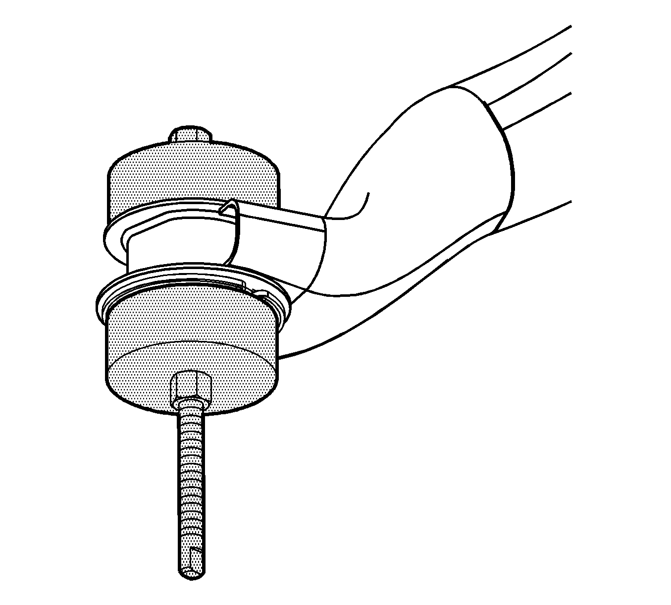
J 45725 Frame Bushing Installer
Removal Procedure
- Remove the spare tire.
- Raise and support the vehicle. Refer to Lifting and Jacking the Vehicle.
- Remove the rear tire and wheel assemblies. Refer to Tire and Wheel Removal and Installation.
- Remove the rear brake caliper bracket bolts.
- Support the rear brake caliper.
- Support the exhaust system on a suitable stand and disconnect the rubber insulator hangers from the exhaust system.
- Lower the exhaust only enough to allow lowering of the suspension crossmember 38 mm (1.5 in).
- Install a jackstand under the front of the rear drive module.
- Install jackstands under the front and rear of the suspension crossmember.
- Remove the suspension crossmember to body bolts.
- Remove the rear axle differential to body bolt.
- Lower the rear drive module and suspension crossmember only enough to service the mount, approximately 38 mm (1.5 in).
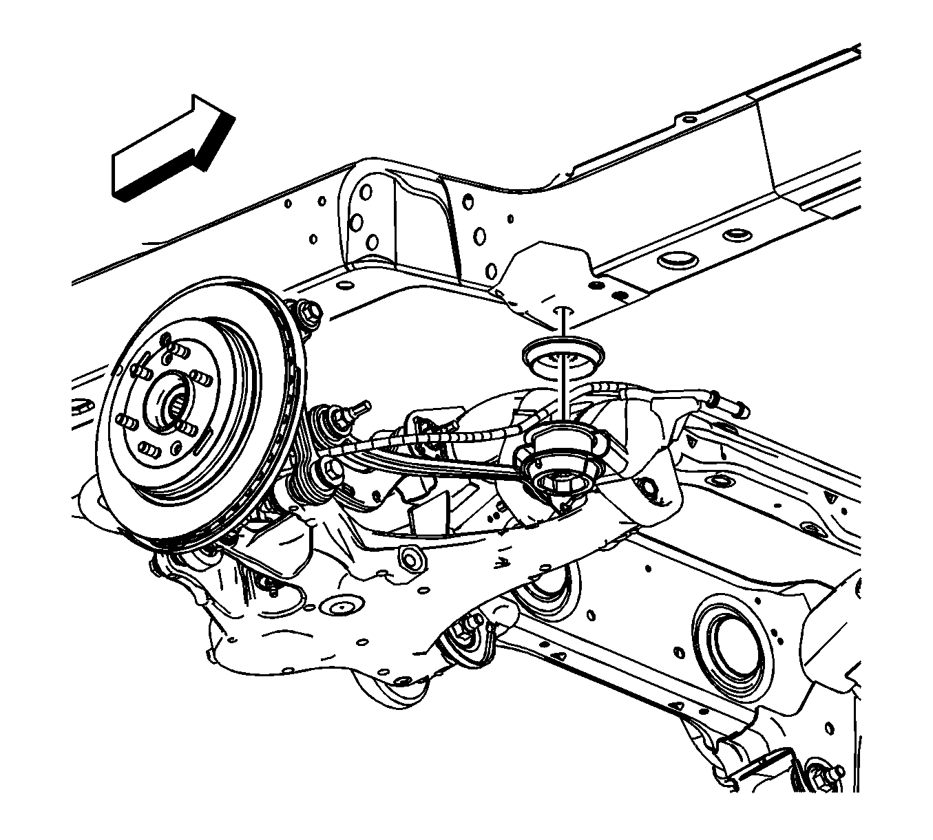
- Remove the upper mount.
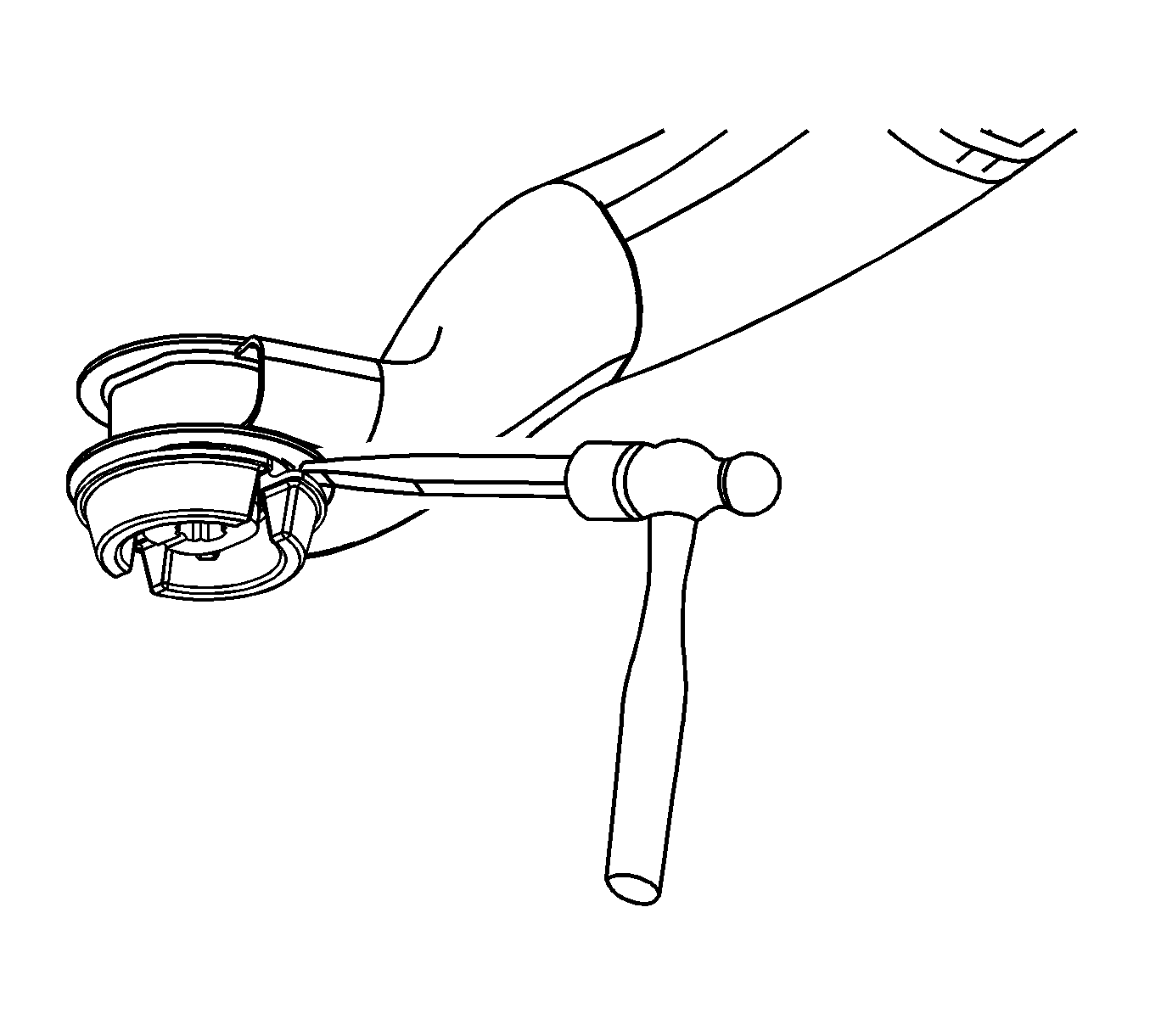
- Remove the lower mount using a flat chisel. Begin extracting the mount by guiding the wedge of the chisel tip between the mount flange lip and the suspension crossmember.
- Continue extracting the mount until it is fully removed from the suspension crossmember.
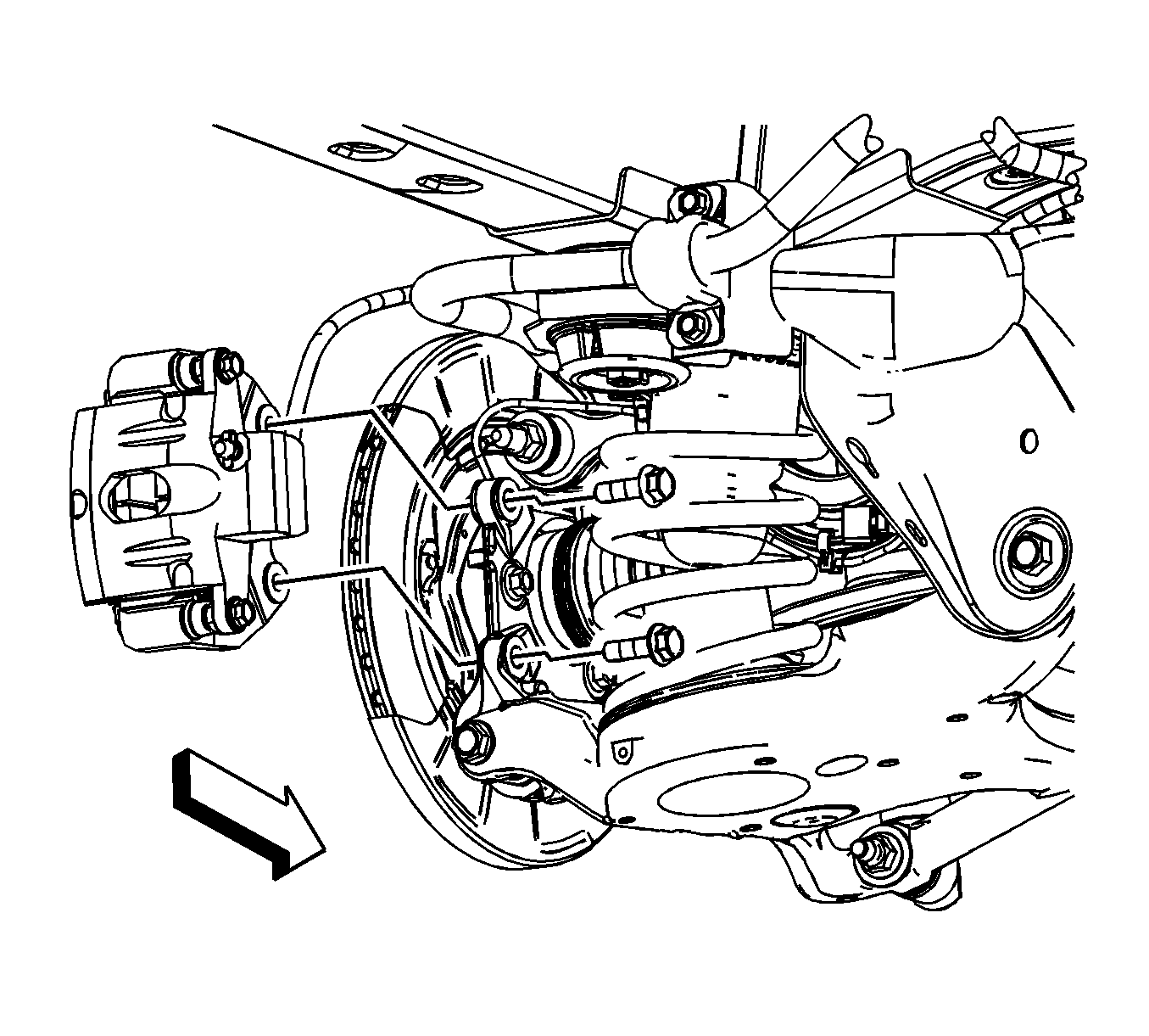
Note: Support the rear brake calipers from the vehicle body not the suspension to prevent stressing of the brake hoses.
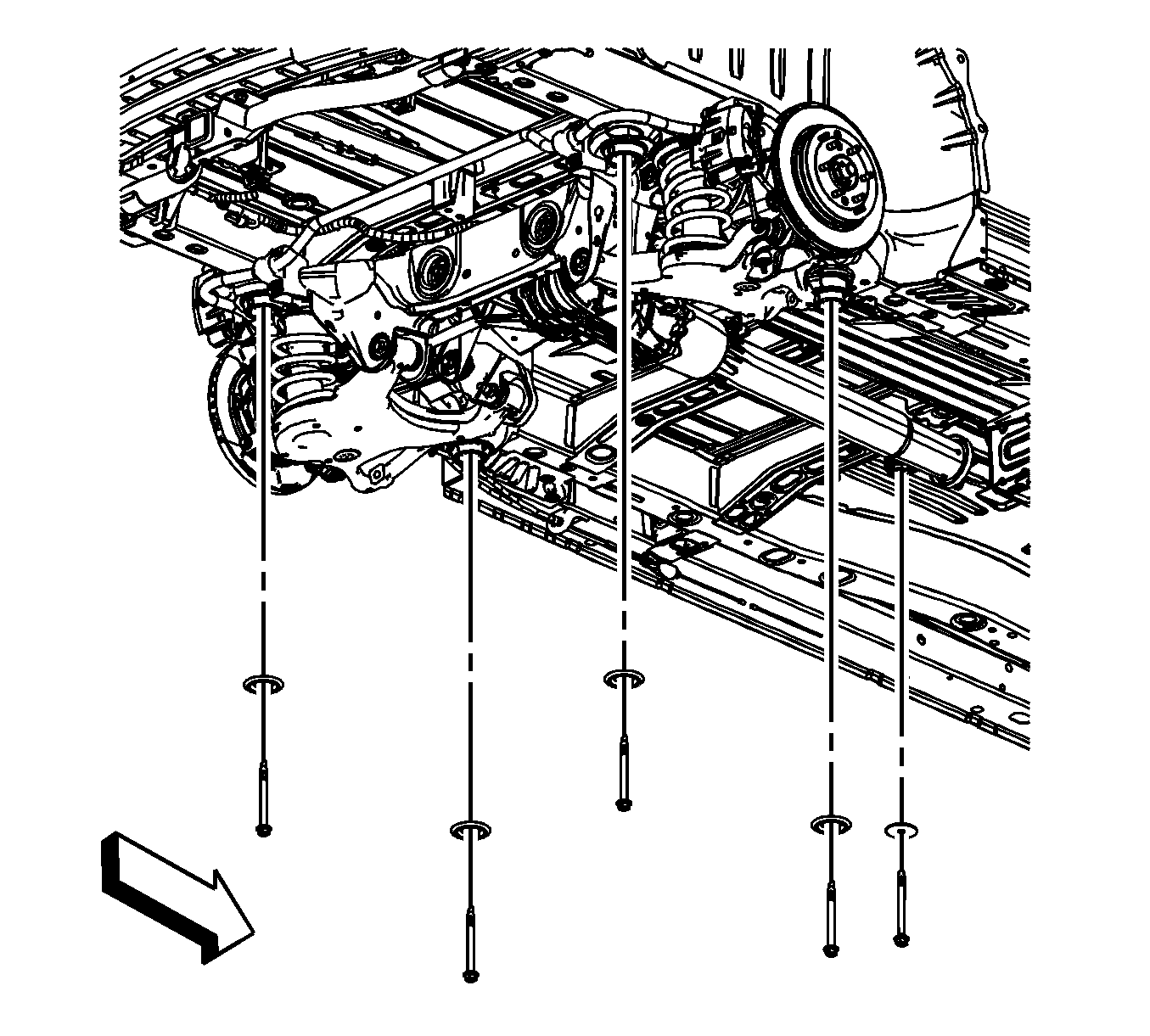
Note: Both the front and rear of the rear drive module must be lowered equally to prevent over stressing the rear drive module bushing and suspension crossmember mounts.
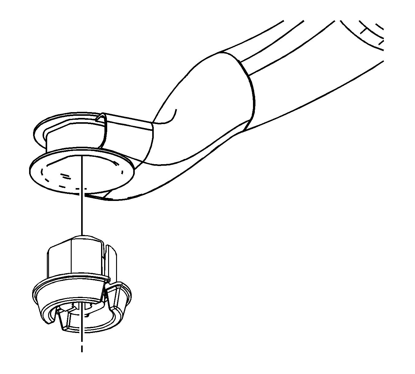
Installation Procedure
- Clean the suspension crossmember mount opening.
- Apply a thin coat of rubber lubricant GM P/N 1051717 (Canadian P/N 5728223), or equivalent to the inside of the suspension crossmember mount opening.
- Apply a thin coat of rubber lubricant GM P/N 1051717 (Canadian P/N 5728223), or equivalent to the suspension crossmember mount.
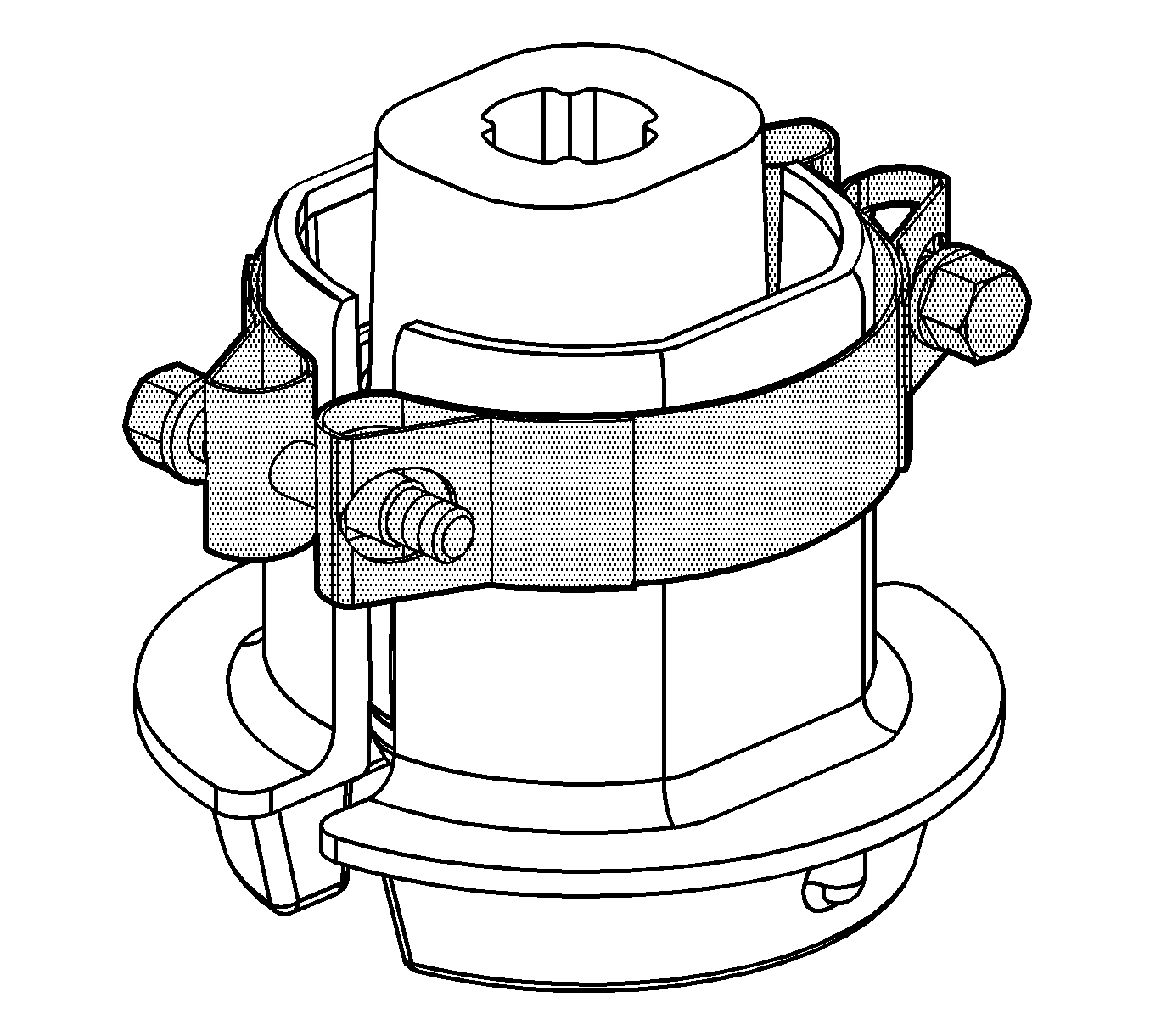
- Install clamp J 45725 Installer onto the mount about 1/8 inch from the top of the mount.
- Align the split of the mount to the front of the suspension crossmember.
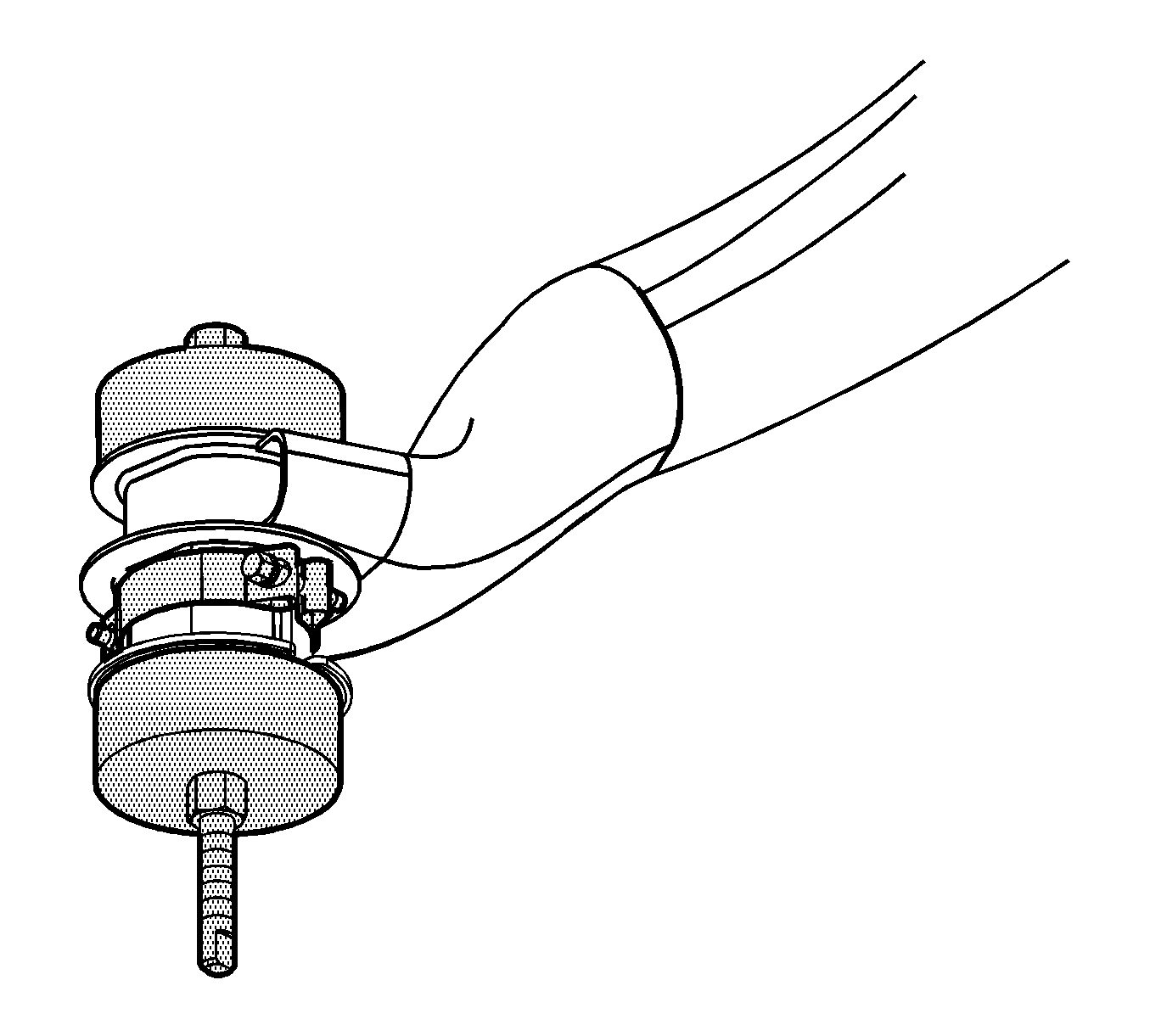
- Install J 45725 Installer to the mount and the suspension crossmember.
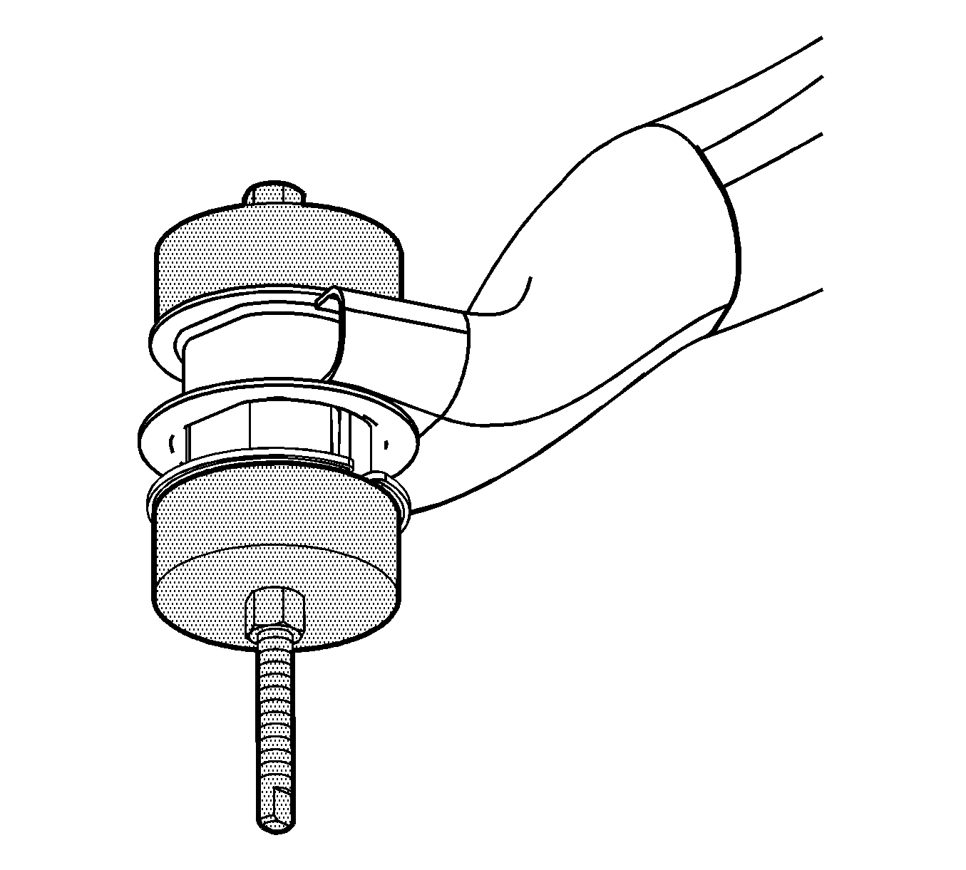
- Using J 45725 Installer install the mount until the mount is halfway recessed in the suspension crossmember.
- Remove only the clamp J 45725 Installer .
- Using J 45725 Installer continue installing the mount until the flange lip of the mount is fully seated to the bottom of the suspension crossmember.
- Remove J 45725 Installer from the mount and the suspension crossmember.
- Install the upper mount.
- Raise the suspension crossmember and rear drive module.
- Install the suspension crossmember to body bolts.
- Install the rear axle differential to body bolt.
- Remove the jackstands.
- Install the rear brake caliper bracket and bolts. Refer to Rear Brake Caliper Bracket Replacement.
- Install the rear tire and wheel assemblies. Refer to Tire and Wheel Removal and Installation.
- Lower the vehicle.
- Install the spare tire.

Caution: Refer to Fastener Caution in the Preface section.

Note: If the suspension crossmember mount bolt does not screw in smoothly, run a tap through the suspension crossmember nut in the body in order to remove foreign material. Ensure the tap does not punch through the underbody.
Do not over tighten the body mount. Over tightening may collapse a spacer or strip a bolt.Tighten
Tighten the bolts to 110 N·m (81 lb ft) plus 90 degrees.
Tighten
Tighten the bolts to 160 N·m (118 lb ft).

Rear Suspension Support Lower Mount Replacement - Front Front Wheel Drive
Special Tools
J 45725 Frame Bushing Installer
Removal Procedure
- Remove the spare tire.
- Raise and support the vehicle. Refer to Lifting and Jacking the Vehicle.
- Remove the rear tire and wheel assemblies. Refer to Tire and Wheel Removal and Installation.
- Remove the rear brake caliper bracket bolts.
- Support the rear brake caliper.
- Support the exhaust system on a suitable stand and disconnect the rubber insulator hangers from the exhaust system.
- Lower the exhaust only enough to allow lowering of the suspension crossmember 38 mm (1.5 in).
- Install jackstands under the front and rear of the suspension crossmember.
- Remove the suspension crossmember to body bolts.
- Lower the suspension crossmember only enough to service the mount, approximately 38 mm (1.5 in).
- Remove the upper mount.
- Remove the lower mount using a flat chisel. Begin extracting the mount by guiding the wedge of the chisel tip between the mount flange lip and the suspension crossmember.
- Continue extracting the mount until it is fully removed from the suspension crossmember.
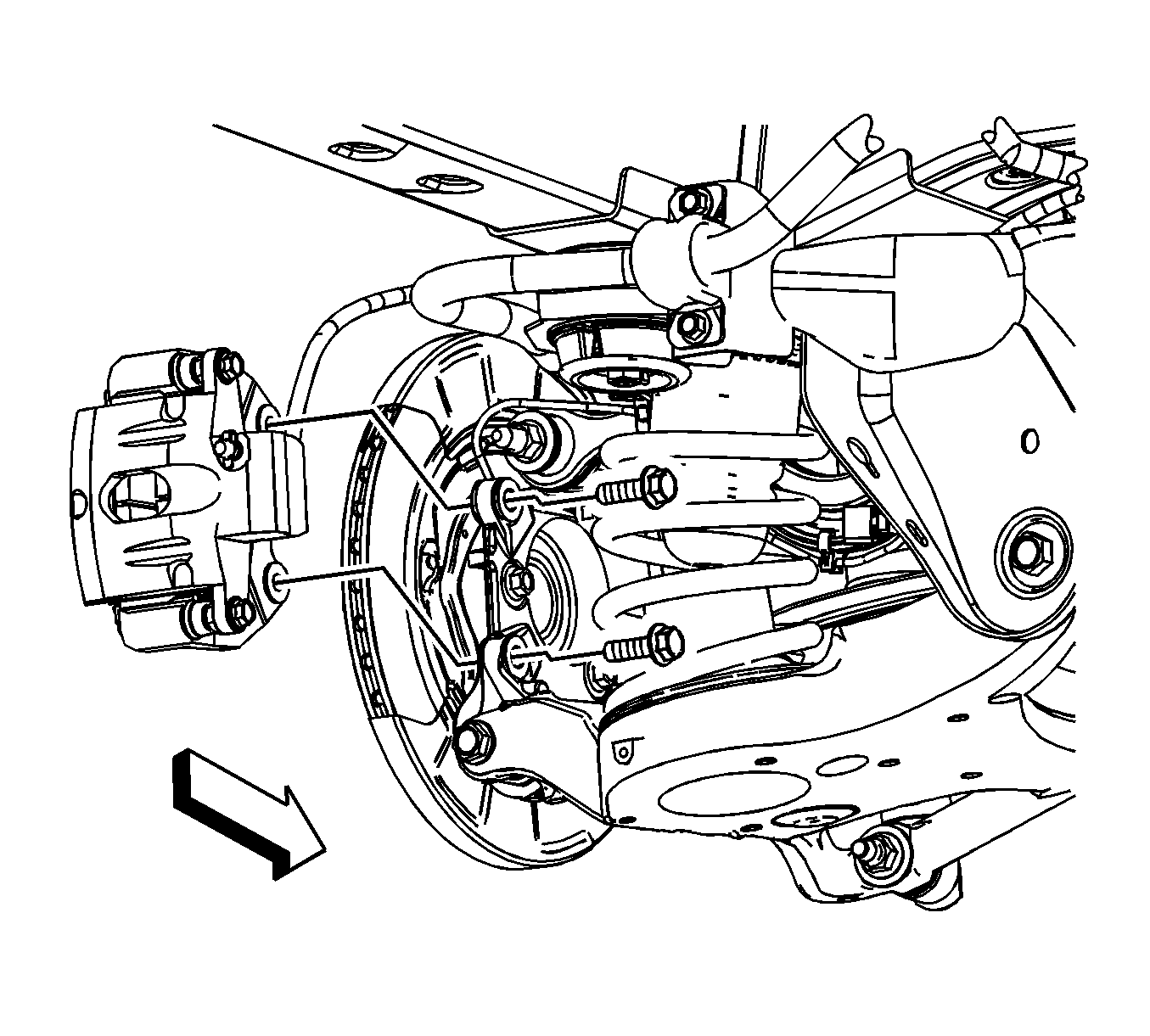
Note: Support the rear brake calipers from the vehicle body not the suspension to prevent stressing of the brake hoses.
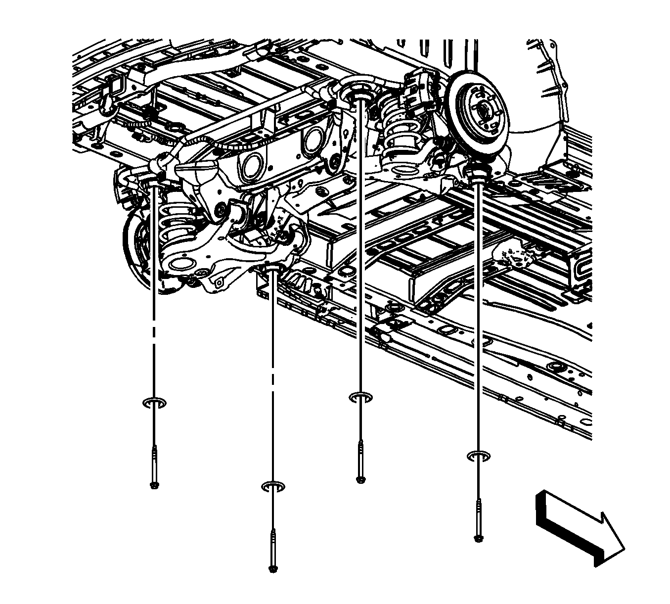
Note: Both the front and rear of the suspension crossmember must be lowered equally to prevent over stressing the mounts.


Installation Procedure
- Clean the frame mount opening.
- Apply a thin coat of rubber lubricant GM P/N 1051717 (Canadian P/N 5728223), or equivalent to the inside of the suspension crossmember mount opening.
- Apply a thin coat of rubber lubricant GM P/N 1051717 (Canadian P/N 5728223), or equivalent to the suspension crossmember mount.
- Install clamp J 45725 Installer onto the mount about 1/8 inch from the top of the mount.
- Align the split of the mount to the front of the suspension crossmember.
- Install J 45725 Installer to the mount and the suspension crossmember.
- Using J 45725 Installer install the mount until the mount is halfway recessed in the suspension crossmember.
- Remove only the clamp J 45725 Installer .
- Using J 45725 Installer continue installing the mount until the flange lip of the mount is fully seated to the bottom of the suspension crossmember.
- Remove J 45725 Installer from the mount and the suspension crossmember.
- Install the upper mount.
- Raise the suspension crossmember.
- Install the suspension crossmember to body bolts.
- Remove the jackstands.
- Install the rear brake caliper bracket and bolts. Refer to Rear Brake Caliper Bracket Replacement.
- Install the rear tire and wheel assemblies. Refer to Tire and Wheel Removal and Installation.
- Lower the vehicle.
- Install the spare tire.


Caution: Refer to Fastener Caution in the Preface section.

Note: If the suspension crossmember mount bolt does not screw in smoothly, run a tap through the frame crossmember nut in the body in order to remove foreign material. Ensure the tap does not punch through the underbody.
Do not over tighten the body mount. Over tightening may collapse a spacer or strip a bolt.Tighten
Tighten the bolts to 110 N·m (81 lb ft) plus 90 degrees.

