
| Subject: | Revised Control Arm Bushing Replacement Procedure |
| Models: | 2005 Chevrolet Uplander |
This bulletin is being issued to revise the Control Arm Bushing Replacement procedure in the Rear Suspension sub-section of the Service Manual. Please replace the current information in the Service Manual with the following information.
The following information has been updated within SI. If you are using a paper version of this Service Manual, please make a reference to this bulletin on the affected page.
Control Arm Bushing Replacement
Tools Required
| • | J 28685 Rear Suspension Bushing Remover/Installer |
| • | J 9519-E Ball Joint Remover/Installer Kit |
Removal Procedure
- Raise and support the vehicle. Refer to Lifting and Jacking the Vehicle in General Information.
- Use a utility stand in order to support the control arm forward of the coil spring.
- Remove the control arm bolts from the rear axle. Refer to Rear Axle Replacement.
- Use the utility stand in order to lower the rear axle enough to gain access to the control arm bushing.
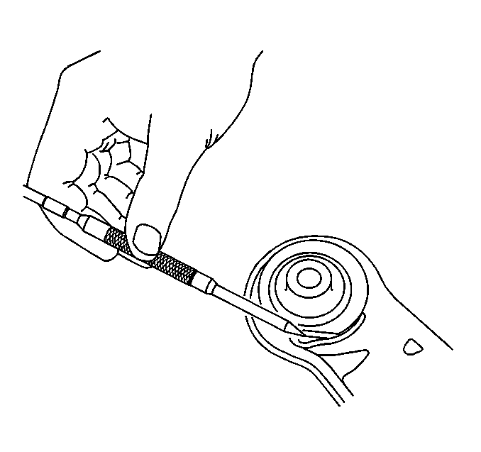
- Mark the orientation of the control arm bushing in the lower control arm.
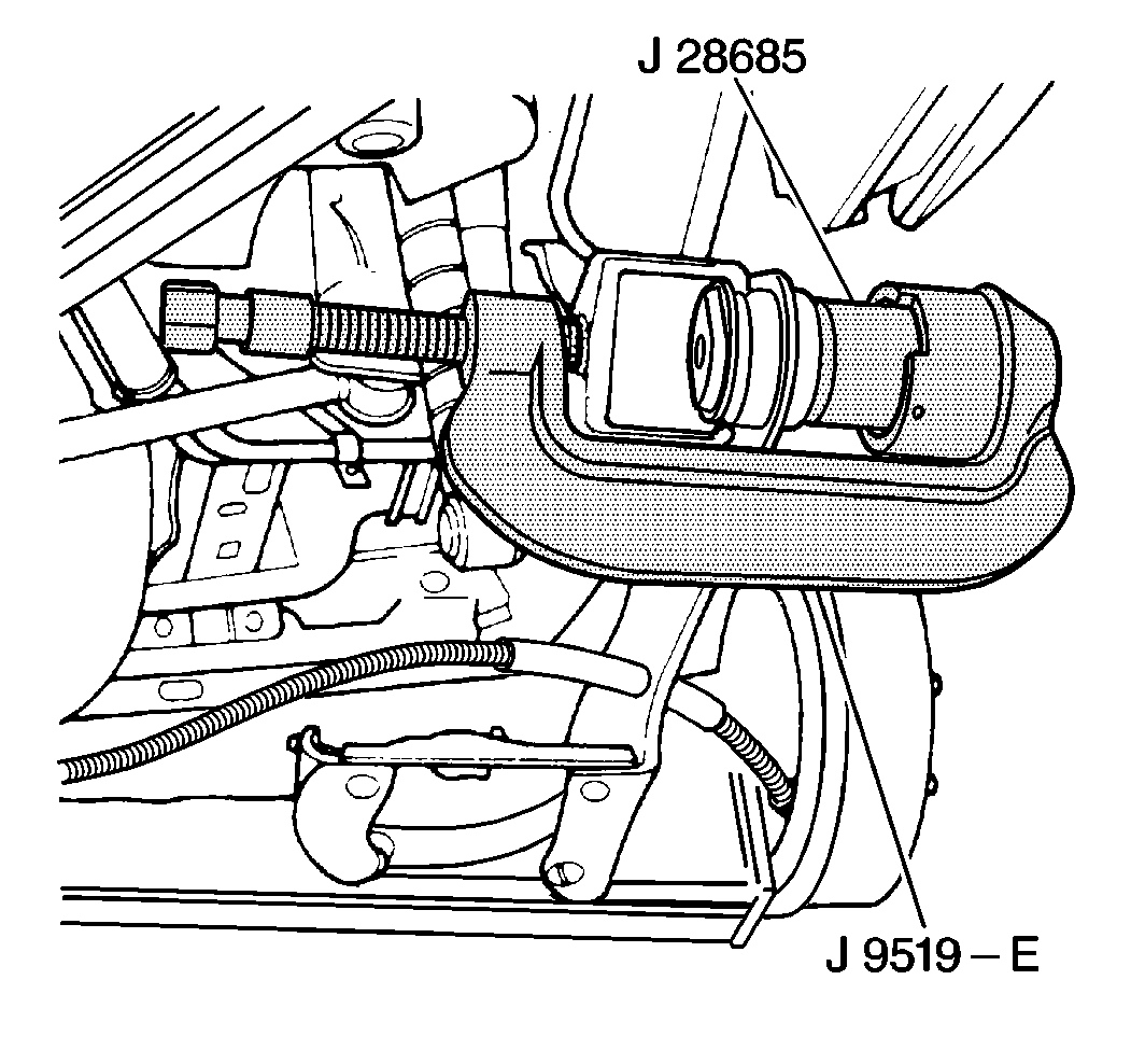
- Use the J 28685 and the J 9519-E in order to remove the control arm bushing.
Installation Procedure
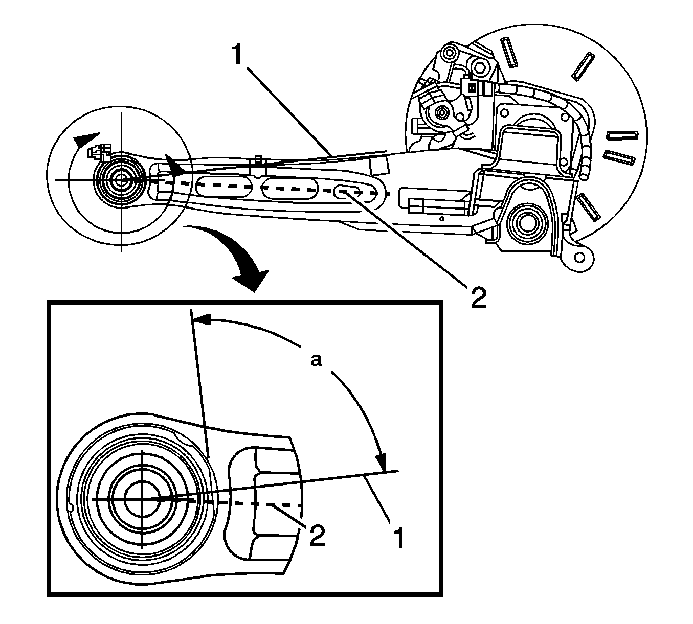
- Align the flat edge of the bushing to be 90 degrees to the fluid axis (1). The fluid axis is 9 degrees from the center line of the control arm.
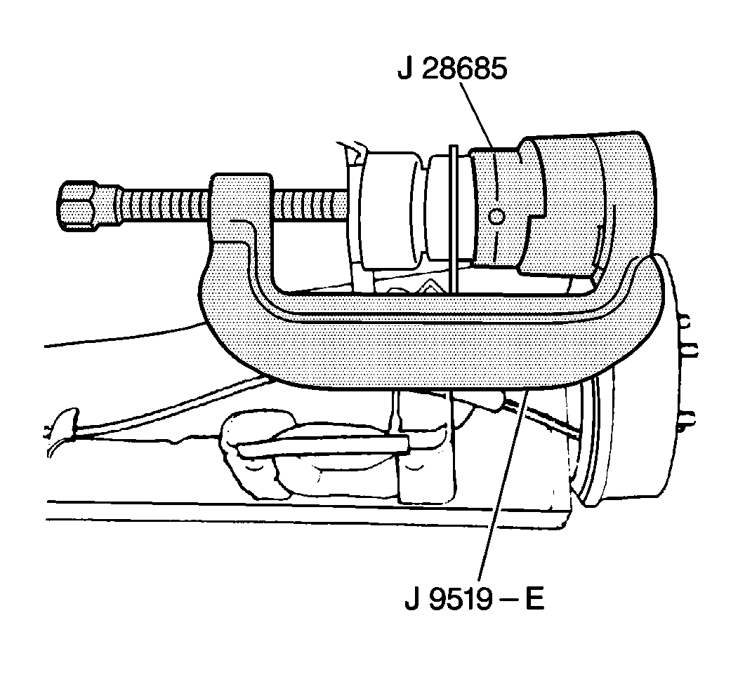
- Use the J 28685 and the J 9519-E in order to install the control arm bushing.
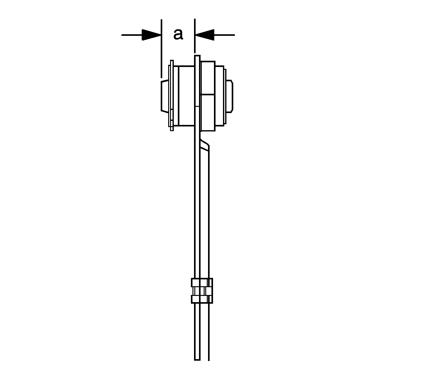
Important: The bushing must extend 30 mm (1.18 in) from the control arm.
- The bushing is installed to the proper depth when the end of the bushing is aligned with the indicator line on the J 28685.
- Use the utility stand in order to raise the rear axle.
- Install the control arm bolt to the rear axle. Refer to Rear Axle Replacement.
- Remove the utility stand.
- Lower the vehicle.


