For 1990-2009 cars only
Removal Procedure
- Remove the left cowl side panel. Refer to Cowl Side Trim Panel Replacement .
- Remove the knee bolster. Refer to Knee Bolster Replacement .
- Disable the SIR system. Refer to SIR Disabling and Enabling .
- Disconnect the electrical connector from the stop lamp switch.
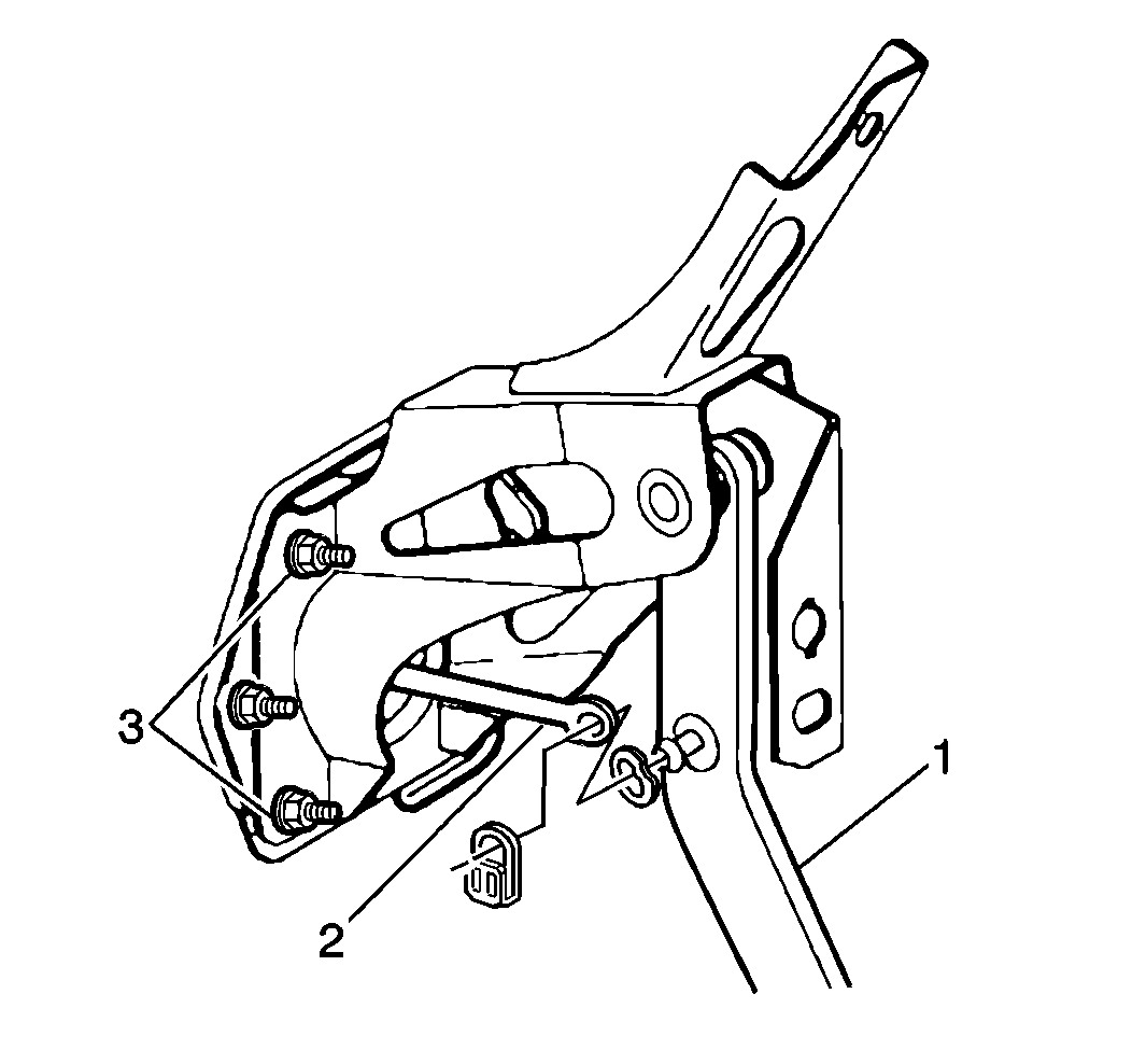
- Remove the booster push rod retaining clip and washer from the brake pedal assembly.
- Remove the accelerator pedal. Refer to Accelerator Pedal Position Sensor Replacement .
- Remove the booster push rod (2) from the brake pedal (1).
- Remove the brake booster mounting nuts (3).
- Remove the digital radio receiver and bracket, if equipped. Refer to Digital Radio Receiver Replacement .
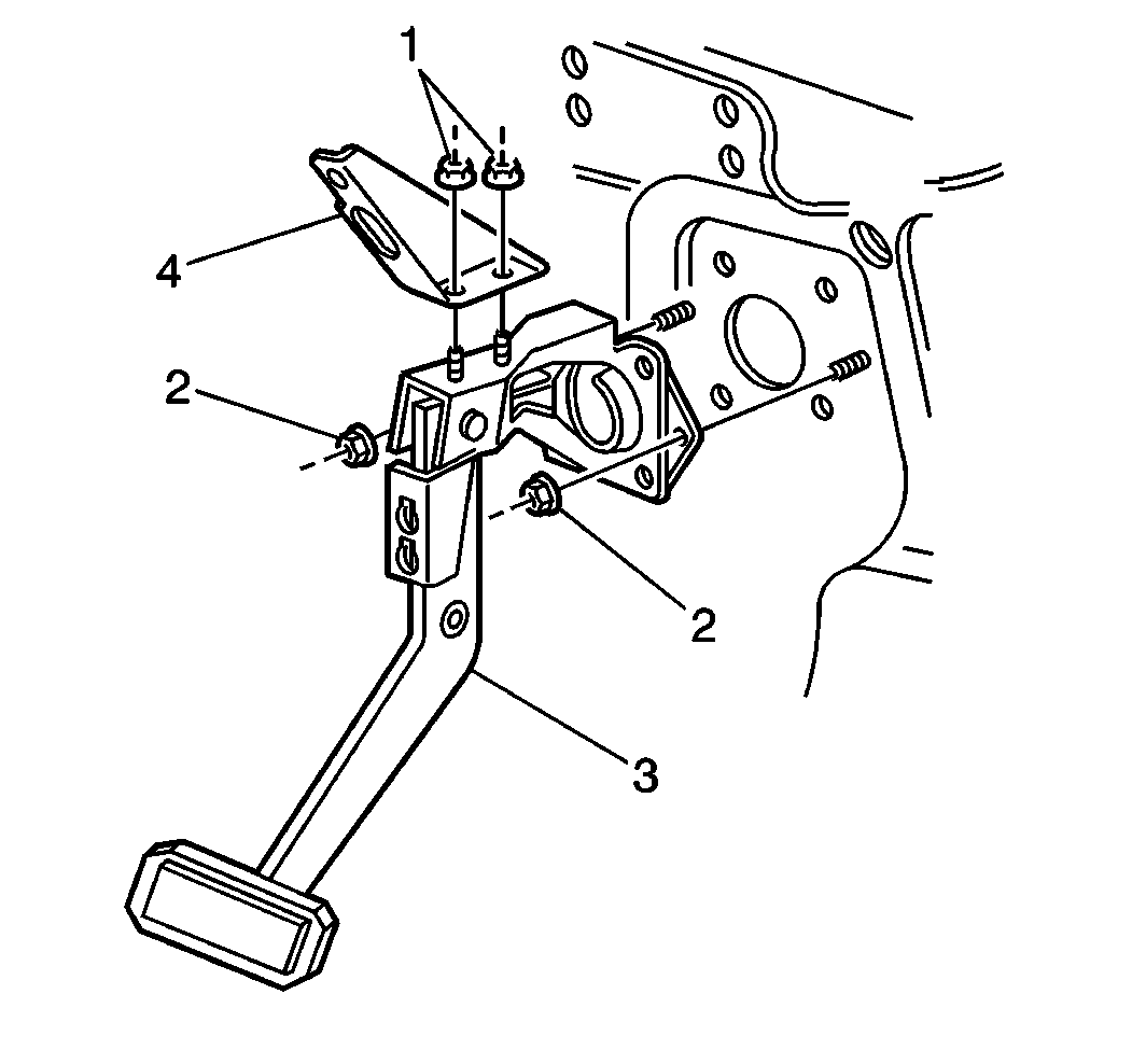
- Remove the brake pedal brace (4) mounting nuts (1).
- Remove the brake pedal brace (4) mounting bolt.
- Remove the brake pedal assembly mounting nuts (2).
- Pull master cylinder and brake booster assembly forward for additional clearance while removing brake pedal assembly.
- Remove the brake pedal assembly with the bracket (4).
- Remove the brake pedal assembly (3) from the vehicle.
- Remove the brake pedal position sensor from the brake pedal assembly . Refer to Brake Pedal Position Sensor Replacement .


Installation Procedure
- Install the brake pedal position sensor to the brake pedal assembly. Refer to Brake Pedal Position Sensor Replacement .
- Position the brake pedal brace (4) to the brake pedal assembly, install the brace mounting nuts (1) and tighten to 10 N·m (89 lb in) .
- Install the brake pedal assembly (3) with the brace to the vehicle.
- Push the master cylinder and brake booster assembly back into position.
- Install the brake pedal brace (4) upper mounting bolt and tighten to 10 N·m (89 lb in) .
- Install the brake pedal assembly mounting nuts (2) and tighten to 25 N·m (18 lb ft) .
- Install the digital radio receiver and bracket if equipped. Refer to Digital Radio Receiver Replacement .
- Install the brake booster mounting nuts (3) and tighten to 25 N·m (18 lb ft) .
- Install the booster push rod (2) to the brake pedal (1).
- Install the washer and the retaining clip.
- Install the accelerator pedal. Refer to Accelerator Pedal Position Sensor Replacement .
- Enable the SIR system. Refer to SIR Disabling and Enabling .
- Connect the electrical connector to the stop lamp switch.
- Calibrate the brake pedal position sensor. Refer to Brake Pedal Position Sensor Calibration .
- Install the knee bolster. Refer to Knee Bolster Replacement .
- Install the left cowl side panel. Refer to Cowl Side Trim Panel Replacement .
Caution: Refer to Fastener Caution in the Preface section.


