For 1990-2009 cars only
Removal Procedure
- If equipped with a power sliding door, disable the PSD system by removing the PSD 15A fuse from the instrument panel (I/P) fuse block.
- Open the sliding door in order to gain access to the center roller bracket pin.
- Support the rear of the sliding door.
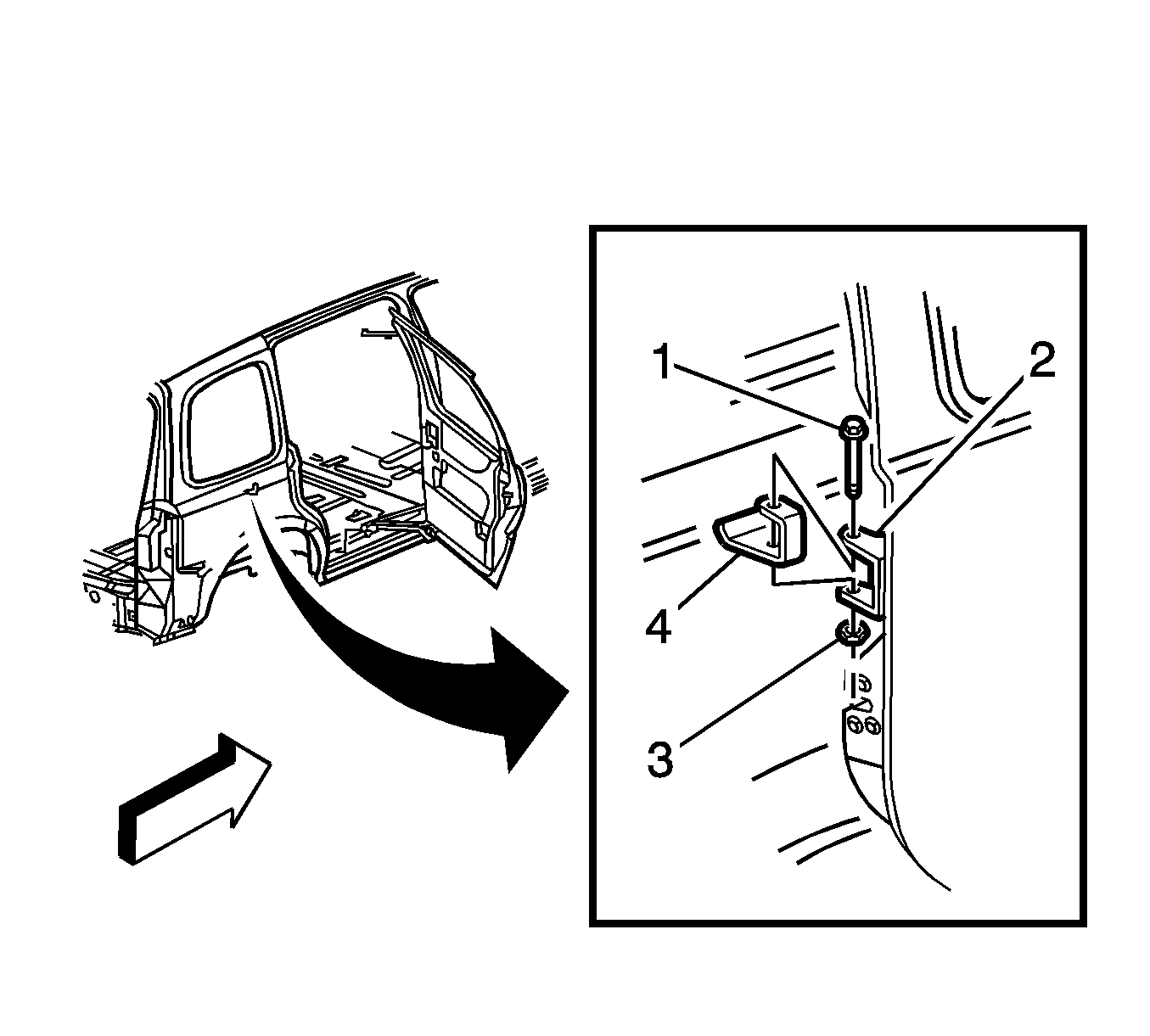
- Remove the pin (1) from the center roller bracket (2).
- Position the center roller bracket to the front radius of the sliding door center track.
- Release cable tension. Refer to Rear Side Door Actuator Cable Tension Adjustment .
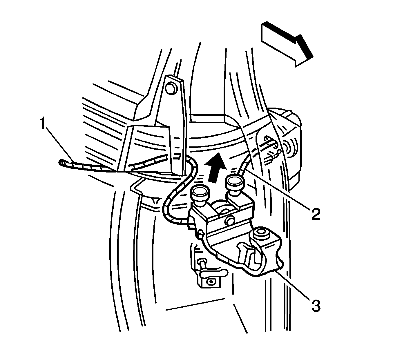
- Remove the cables (1, 2) from the rear roller bracket (power sliding door only).
- Lift the center roller bracket (3) upwards and remove the bracket from the center track.
Important: By removing the power sliding door (PSD) 15A fuse, the low current logic power for both the LH and RH power sliding door modules (PSDM) will be interrupted and both PSDs will be inoperative.


Installation Procedure
- Attach the cable ends.
- Position the sliding door center roller bracket to the front radius of the sliding door center track.
- Lower the sliding door center roller bracket to sliding door center track down and into the sliding door center track.
- Install the cable to the rear roller bracket.
- Adjust cable tension. Refer to Rear Side Door Actuator Cable Tension Adjustment .
- Position the sliding door center roller bracket (2) to the rear of the track or until the pin holes are aligned.
- Install the pin (1) to the sliding door center roller bracket.
- Remove the support from the power sliding door.
- If equipped with a power sliding door, enable the PSD system by installing the PSD 15A fuse into the I/P fuse block.
- Manually open and close the rear sliding door in order to verify the door fit and the door latch/unlatch operation.
- Test the cable tension again after manually moving the door.

Important: Ensure that the power sliding door cable barrels are properly installed into the sliding door center roller bracket cable retaining items located on the roller bracket.

Important: By installing the 15A fuse, the low current logic power will be restored to both the LH and RH PSDMs and the PSDs will be operational. However, both PSDMs will have to learn the full open and full closed positions of the PSD. Refer to Rear Side Door Actuator Control Module Programming and Setup .
