Special Tools
J 35910 Drive Axle Seal Clamp Pliers
Disassemble Procedure
- Clamp the wheel drive shaft in a soft jawed vise.
- Using a hand grinder, remove the boot retaining clamp (4) and discard the clamp.
- Using a pair of side cutters, remove the boot clamp (4) and discard the clamp.
- Using the appropriate tool, remove the large boot retaining clamp (2) and discard the retaining clamp.
- Remove the boot (4) from the tripot bushing (2).
- Remove the inner tripot housing (1) and the tripot bushing (2) from the wheel drive shaft (3).
- Using the appropriate tool, remove the outer retaining ring (1) from the wheel drive shaft (5).
- Remove the spider (2) from the wheel drive shaft (5).
- Using the appropriate tool, remove the inner retaining ring (1) from the wheel drive shaft (5).
- Remove the boot (4) from the wheel drive shaft (5).
- Inspect the inner wheel drive shaft joint. Refer to Wheel Drive Shaft Inner Joint Inspection.
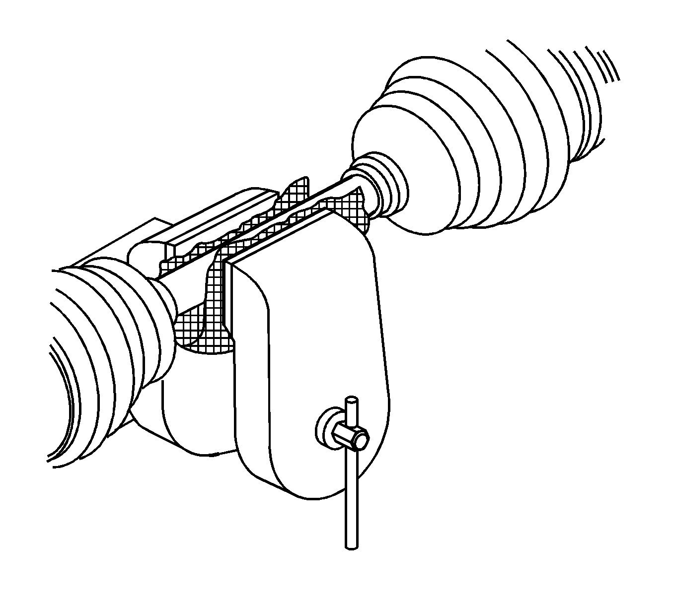
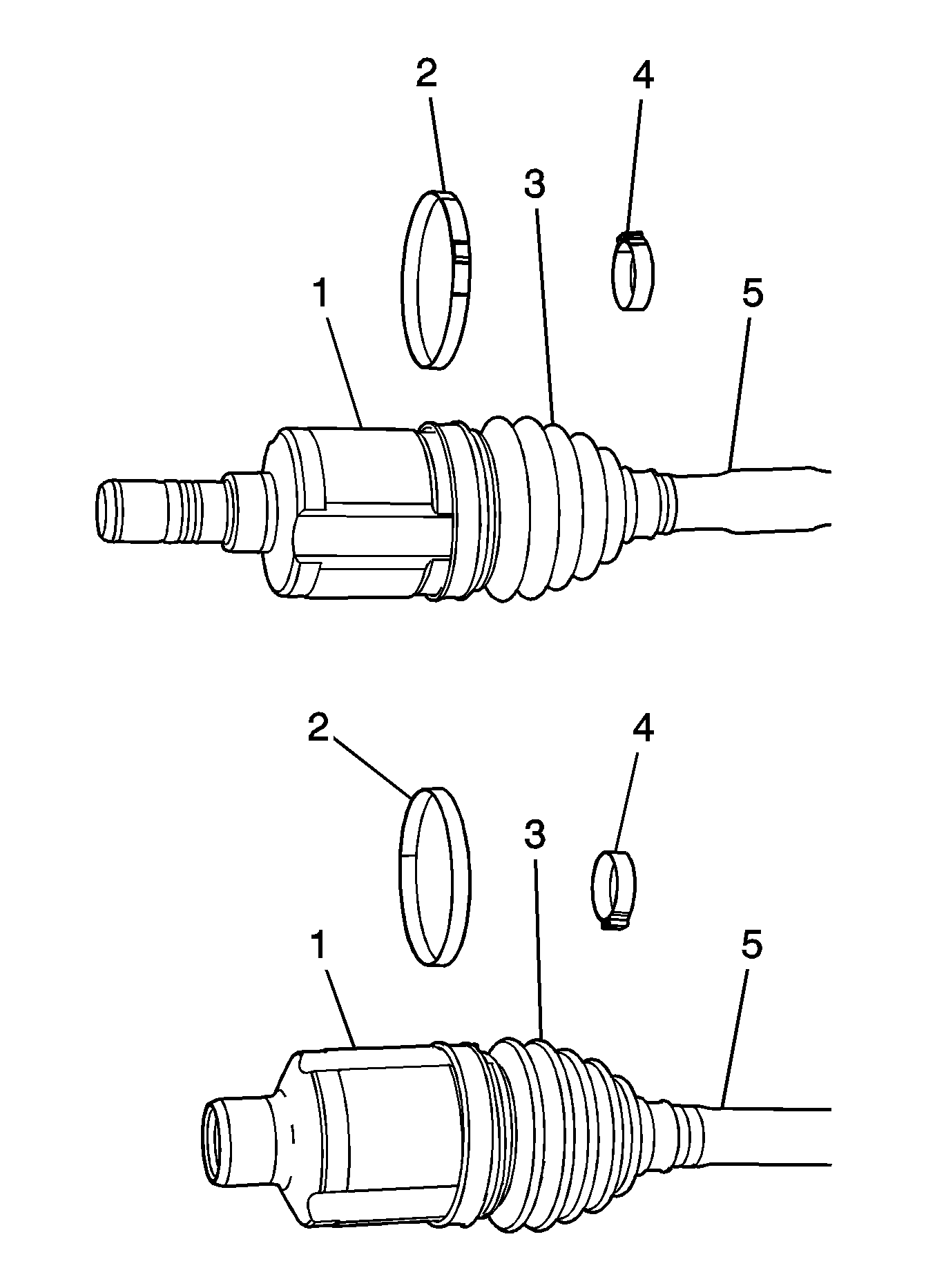
Notice: Do not cut through the wheel drive shaft inboard or outboard boot during service. Cutting through the boot may damage the sealing surface of the housing and the tripot or the constant velocity joint bushing. Damage to the sealing surface may lead to water and dirt intrusion and premature wear of the constant velocity joint.
Important: The following service procedure is for those vehicles equipped a swage style boot clamp. For all others, proceed to step 3.
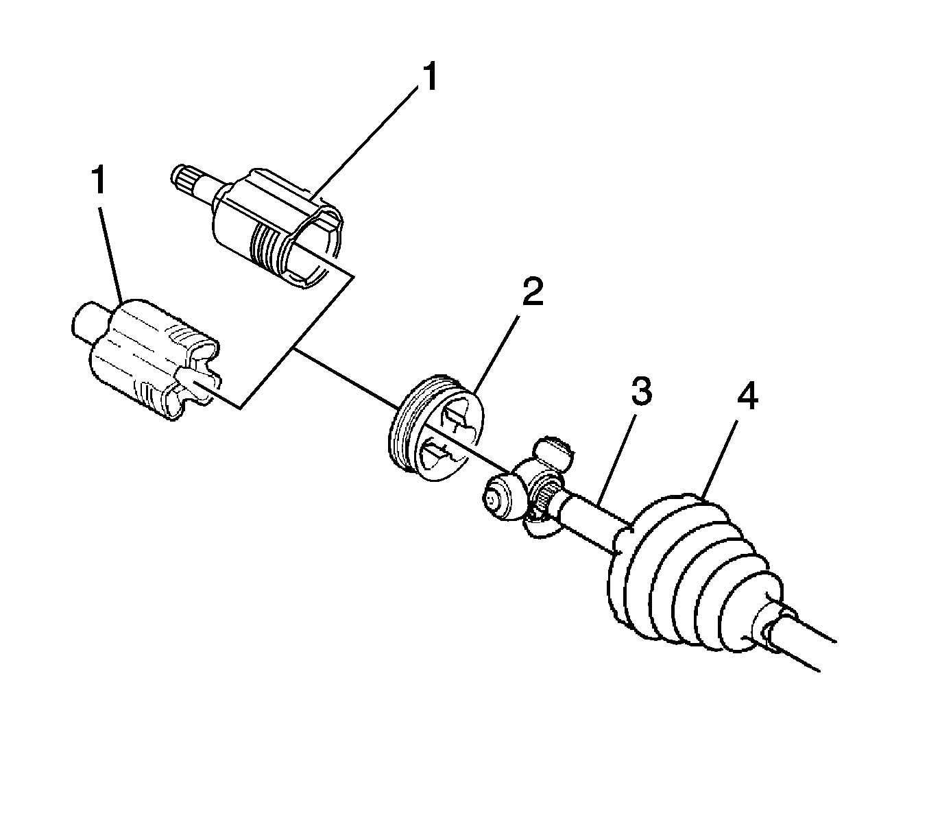
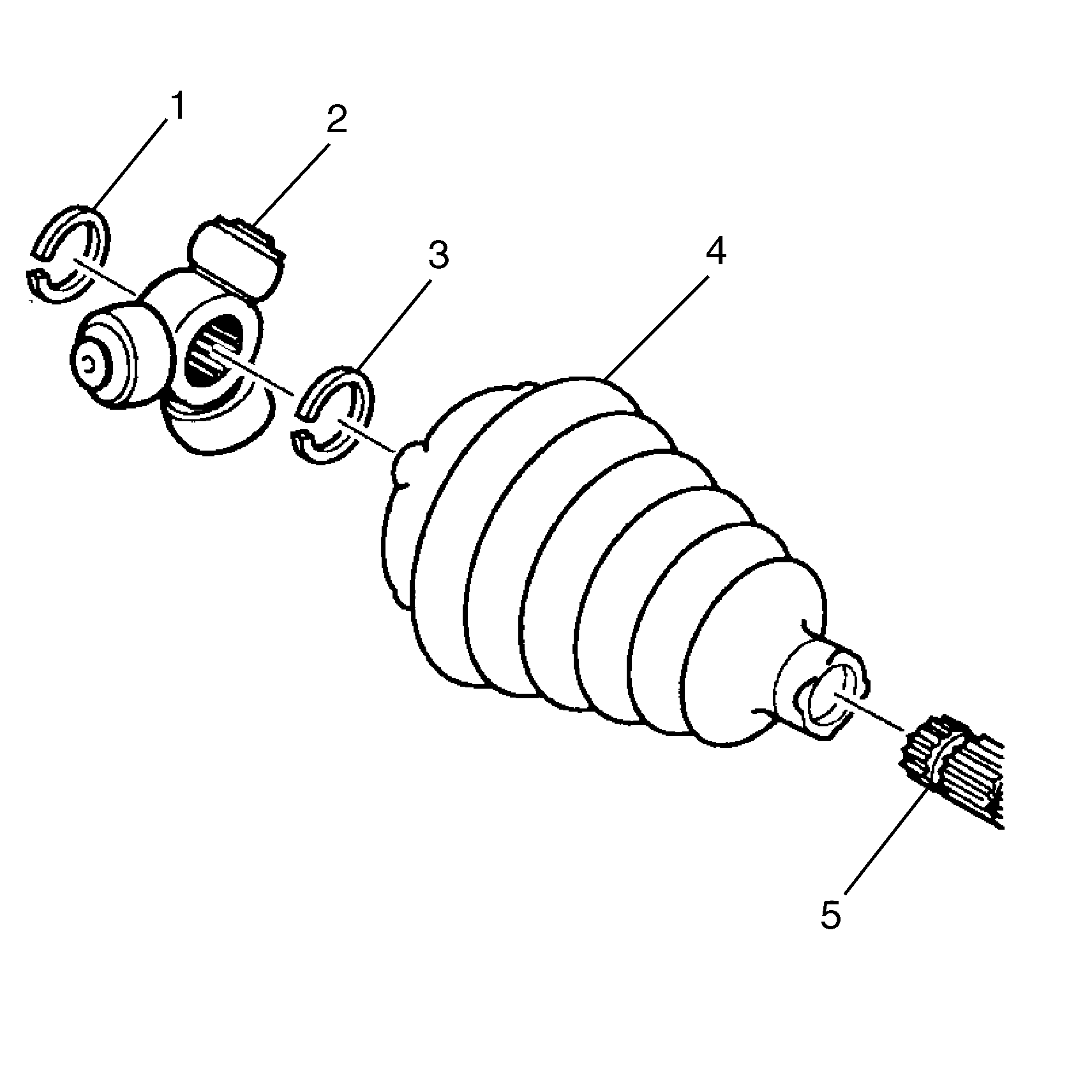
Important: If the tripot has a retaining ring located after it, proceed to step 9. If not, skip step 9 and proceed to step 10.
Assemble Procedure
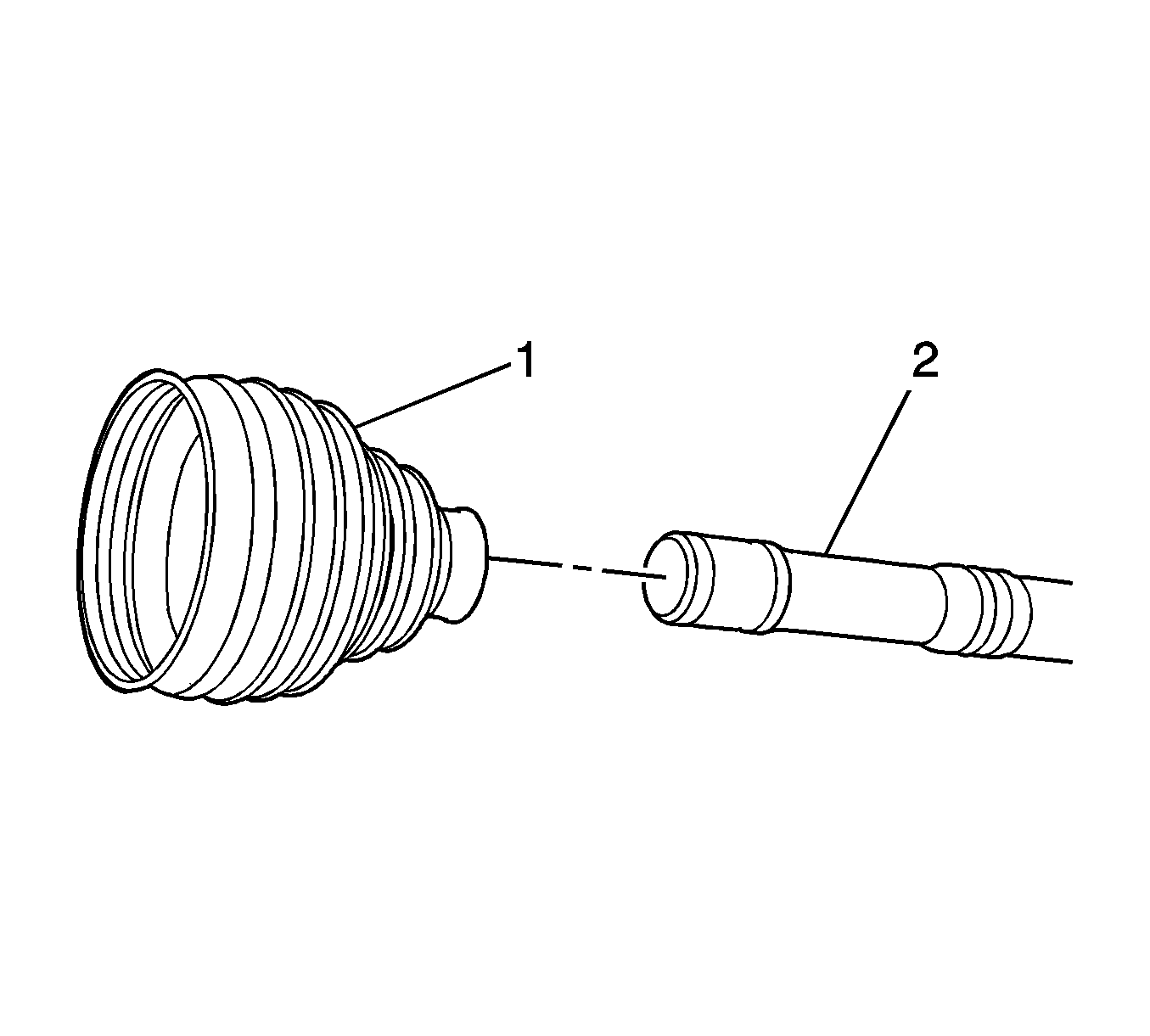
- Install the boot (1) on the axle shaft (2).
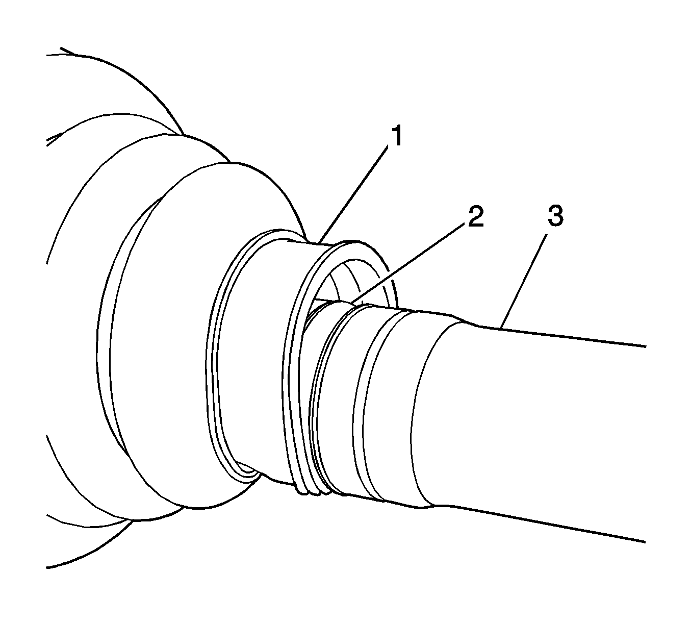
- Ensure that the boot (1) is properly seated in the groove (2) in the wheel drive shaft (3).
- Install the boot clamp on the boot.
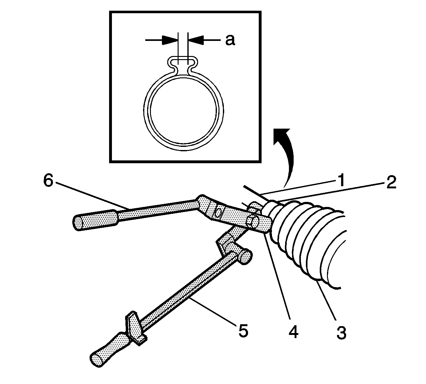
- Install the clamp (2) on the wheel drive shaft (1).
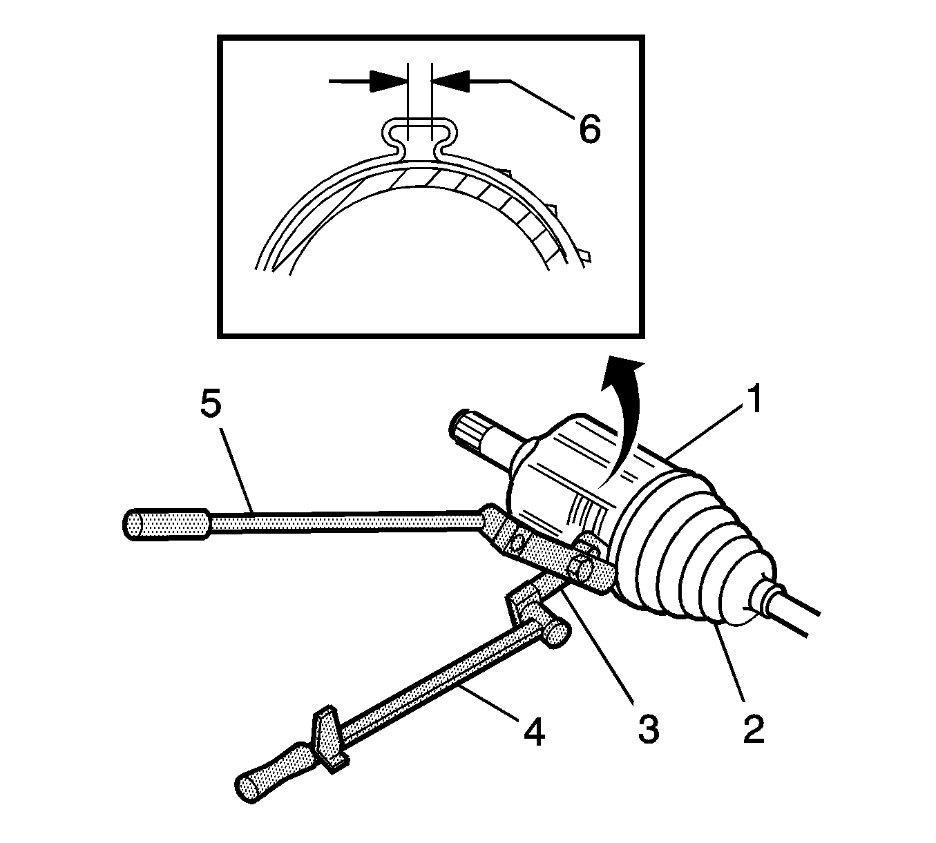
- Using the J 35910 (4), torque wrench (5) and the breaker bar (6), tighten the clamp until the gap (A) in the clamp reaches 2.15 mm (.085 inch).
- Using the appropriate tool, install the inner retaining ring (3), if equipped.
- Install the spider (2) on the wheel drive shaft (5).
- Using the appropriate tool, install the outer retaining ring (1).
- Install the tripot bushing (2), the tripot housing (1) on to the wheel drive shaft (3).
- Install the tripot housing (1) on the boot (4).
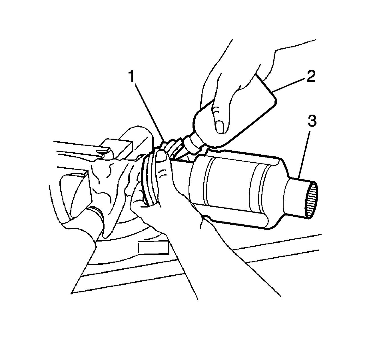
- Place approximately half the container of grease from the service kit in the boot and the half in the tripod housing.
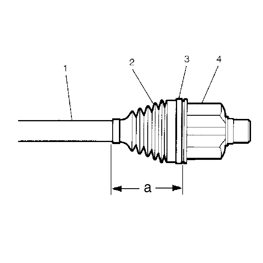
- Install the outer boot clamp (3) on the boot (2) and the tripot housing and the bushing (4).
- Measure the distance from the rear of the boot to the front of the boot clamp (a) the distance a will equal 95 mm (3.75 inch)
- Using the J 35910 (3), torque wrench (4), and the breaker bar (5), tighten the clamp (2).
- The gap of (A) should be 2.60 mm (0.102 inch).
- Rotate the tripot housing several times to distribute the grease.


Tighten
Tighten the clamp (2) to 176 N·m (130 lb ft).
Important: If the gap dimension is larger than the given specification, continue to tighten the clamp until the specification is reached.
