Park or Neutral - Engine Running Park - Without Touch Activated Power
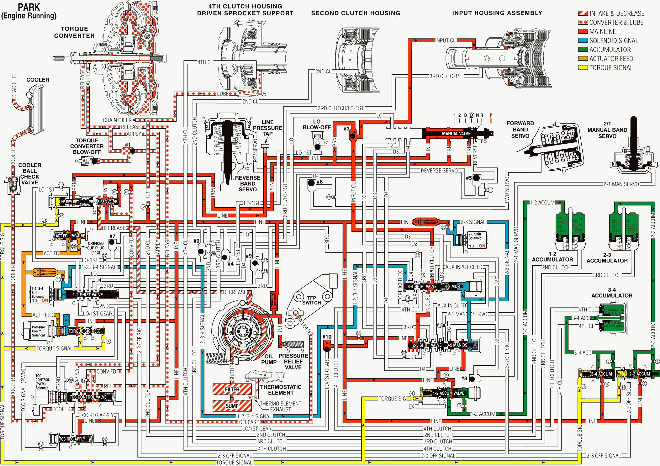
When the gear selector lever is in the PARK (P) position and the engine is running, fluid is drawn into the oil pump and line pressure is then directed to the following control devices:
Pressure Regulator Valve (313)
Regulates pump output (line pressure) in response to torque signal fluid pressure acting on the boost valve, spring force and line pressure acting on the end of the valve. Line pressure is directed to the manual valve, 3 accumulator valves, torque signal regulator valve, pressure relief valve, TCC regulator valve, #10 ball check valve and 2-3 shift valve, 3-2 manual downshift valve, 3-4 shift valve, 2-3 shift solenoid valve, #3 ball check valve and input clutch, and actuator feed limit valve.
Actuator Feed Limit Valve (414)
Line pressure is routed to the valve and limited to a maximum pressure as it passes through the valve and enters the actuator feed circuit. Actuator feed is then routed to the pressure control solenoid valve and into the 1-2, 3-4 shift solenoid valve.
Pressure Control (PC) Solenoid Valve (322)
Controlled by the PCM, the PC solenoid valve regulates filtered actuator feed pressure entering the torque signal circuit. Torque signal fluid is then routed to the pressure regulator valve, the 1-2, 2-3 and 3-4 accumulator valves.
Torque Signal Regulator Valve (321)
Regulates line pressure into the torque signal fluid circuit. This regulation is controlled by filtered actuator feed fluid pressure from the PC solenoid valve.
Line Pressure Relief Valve (324)
Exhausts line pressure above 1,690-2,480 kPa (450-360 psi).
Manual Valve (404)
The manual valve is moved to the NEUTRAL position and blocks line pressure from entering the Reverse fluid circuit. The reverse fluid circuit is opened to an exhaust at the manual valve.
Transmission Fluid Pressure (TFP) Manual Valve Position Switch Assembly (34)
The automatic transmission fluid pressure (TFP) switch is attached to the valve body and consists of one fluid pressure switch that monitors TCC release pressure. This switch is used as a diagnostic tool to confirm that the TCC is actually off when it has been commanded off by the PCM.
The TCC release switch is a normally closed pressure switch. A normally closed switch allows current to flow from the positive contact through the switch to ground when no fluid is present. Fluid pressure moves the diaphragm to disconnect the positive and ground contacts, opening the switch and stopping current flow. This change in switch state electronically signals the PCM that the TCC is released.
1-2, 3-4 Shift Solenoid Valve (315A)
Controlled by the powertrain control module (PCM), the 1-2, 3-4 shift solenoid (SS) valve is energized (On) in PARK range. Actuator feed pressure moves the 1-2 shift valve (318) against spring pressure and directs line fluid into the 1-2, 3-4 signal passage. 1-2, 3-4 signal fluid is then directed to the 3-4 shift valve (362).
2-3 Shift Solenoid Valve (315B)
Controlled by the powertrain control module (PCM), the 2-3 shift solenoid (SS) valve is energized (On) in PARK range and directs line pressure into the 2-3 signal passage. 2-3 signal fluid directed to the 4-3 manual downshift valve (360) and moves the valve against spring pressure, and also the 3-2 manual downshift valve (356).
1-2 Shift Valve (318)
1-2 signal fluid pressure holds the valve in the downshifted position against spring force.
2-3 Shift Valve (357)
In PARK range, line pressure passes through the 2-3 shift valve (357) and line pressure feeds the input clutch feed passage. Line pressure then passes through the 3-4 shift valve (362) and around the #3 ball check valve (372), located in the case cover) in order to apply the input clutch. Although the input clutch is applied and the input sprag is holding, these conditions are not effective because neither the forward band assembly (688) nor the reverse band assembly (615) is applied.
1-2, 2-3 and 3-4 Accumulator Valves (350, 344, 341)
Line pressure is regulated into accumulator fluid pressure. This regulation is basically controlled by torque signal fluid pressure acting on the end of the valve.
1-2, 2-3 and 3-4 Accumulator Assemblies
Accumulator fluid is routed to each of the accumulator assemblies in preparation for upshifts. The fluid routed to the 1-2, 2-3 and 3-4 accumulators is orificed.
Pressure Regulator Valve (313) (Torque Converter/Cooler and Lube Circuits)
Line pressure at the valve enters the converter feed circuit which is then routed to the TCC control valve.
TCC Control Valve (335)
Spring pressure holds the valve in the released position. Converter feed fluid is directed to the release circuit. Release fluid seats #1 ball check valve and feeds the TCC blow-off. Release fluid feeds the TCC on the cover side of the pressure plate, exits the TCC through the apply circuit, then feeds the cooler circuit at the TCC control valve. Cooler fluid passes through the ball check valve, through the cooler, then returns to the transmission and feeds the rear lube circuit. A front lube circuit is fed from orificed line pressure.
Park - Engine Running - Without Touch Activated Power

Park or Neutral - Engine Running Park - With Touch Activated Power
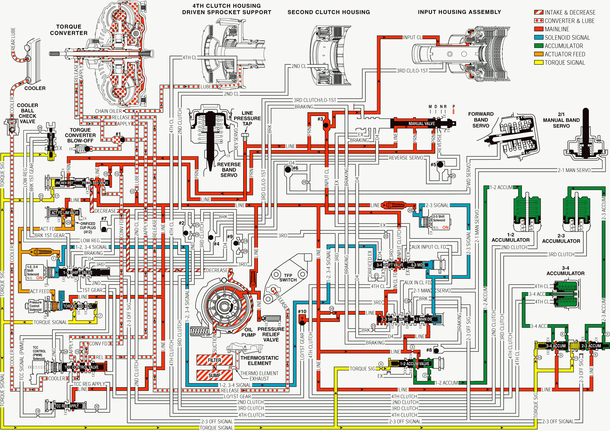
When the gear selector lever is in the PARK (P) position and the engine is running, fluid is drawn into the oil pump and line pressure is then directed to the following control devices:
Pressure Regulator Valve (313)
Regulates pump output (line pressure) in response to torque signal fluid pressure acting on the boost valve, spring force and line pressure acting on the end of the valve. Line pressure is directed to the manual valve, 3 accumulator valves, torque signal regulator valve, pressure relief valve, TCC regulator valve, #10 ball check valve and 2-3 shift valve, 3-2 manual downshift valve, 3-4 shift valve, 2-3 shift solenoid valve, #3 ball check valve and input clutch, and actuator feed limit valve.
Actuator Feed Limit Valve (414)
Line pressure is routed to the valve and limited to a maximum pressure as it passes through the valve and enters the actuator feed circuit. Actuator feed is then routed to the pressure control solenoid valve and into the 1-2, 3-4 shift solenoid valve.
Pressure Control (PC) Solenoid Valve (322)
Controlled by the PCM, the PC solenoid valve regulates filtered actuator feed pressure entering the torque signal circuit. Torque signal fluid is then routed to the pressure regulator valve, the 1-2, 2-3 and 3-4 accumulator valves.
Torque Signal Regulator Valve (321)
Regulates line pressure into the torque signal fluid circuit. This regulation is controlled by filtered actuator feed fluid pressure from the PC solenoid valve.
Line Pressure Relief Valve (324)
Exhausts line pressure above 1,690-2,480 kPa (450-360 psi).
Manual Valve (404)
The manual valve is moved to the NEUTRAL position and blocks line pressure from entering the Reverse fluid circuit. The reverse fluid circuit is opened to an exhaust at the manual valve.
Transmission Fluid Pressure (TFP) Manual Valve Position Switch Assembly (34)
The automatic transmission fluid pressure (TFP) switch is attached to the valve body and consists of one fluid pressure switch that monitors TCC release pressure. This switch is used as a diagnostic tool to confirm that the TCC is actually off when it has been commanded off by the PCM.
The TCC release switch is a normally closed pressure switch. A normally closed switch allows current to flow from the positive contact through the switch to ground when no fluid is present. Fluid pressure moves the diaphragm to disconnect the positive and ground contacts, opening the switch and stopping current flow. This change in switch state electronically signals the PCM that the TCC is released.
1-2, 3-4 Shift Solenoid Valve (315A)
Controlled by the powertrain control module (PCM), the 1-2, 3-4 shift solenoid (SS) valve is energized (On) in PARK range. Actuator feed pressure moves the 1-2 shift valve (318) against spring pressure and directs line fluid into the 1-2, 3-4 signal passage. 1-2, 3-4 signal fluid is then directed to the 3-4 shift valve (362).
2-3 Shift Solenoid Valve (315B)
Controlled by the powertrain control module (PCM), the 2-3 shift solenoid (SS) valve is energized (On) in PARK range and directs line pressure into the 2-3 signal passage. 2-3 signal fluid directed to the 4-3 manual downshift valve (360) and moves the valve against spring pressure, and also the 3-2 manual downshift valve (356).
1-2 Shift Valve (318)
1-2 signal fluid pressure holds the valve in the downshifted position against spring force.
2-3 Shift Valve (357)
In PARK range, line pressure passes through the 2-3 shift valve (357) and line pressure feeds the input clutch feed passage. Line pressure then passes through the 3-4 shift valve (362) and around the #3 ball check valve (372), located in the case cover) in order to apply the input clutch. Although the input clutch is applied and the input sprag is holding, these conditions are not effective because neither the forward band assembly (688) nor the reverse band assembly (615) is applied.
1-2, 2-3 and 3-4 Accumulator Valves (350, 344, 341)
Line pressure is regulated into accumulator fluid pressure. This regulation is basically controlled by torque signal fluid pressure acting on the end of the valve.
1-2, 2-3 and 3-4 Accumulator Assemblies
Accumulator fluid is routed to each of the accumulator assemblies in preparation for upshifts. The fluid routed to the 1-2, 2-3 and 3-4 accumulators is orificed.
Pressure Regulator Valve (313) (Torque Converter/Cooler and Lube Circuits)
Line pressure at the valve enters the converter feed circuit which is then routed to the TCC control valve.
TCC Control Valve (335)
Spring pressure holds the valve in the released position. Converter feed fluid is directed to the release circuit. Release fluid seats #1 ball check valve and feeds the TCC blow-off. Release fluid feeds the TCC on the cover side of the pressure plate, exits the TCC through the apply circuit, then feeds the cooler circuit at the TCC control valve. Cooler fluid passes through the ball check valve, through the cooler, then returns to the transmission and feeds the rear lube circuit. A front lube circuit is fed from orificed line pressure.
Park - Engine Running - With Touch Activated Power

Park or Neutral - Engine Running Neutral-Without Touch Activated Power
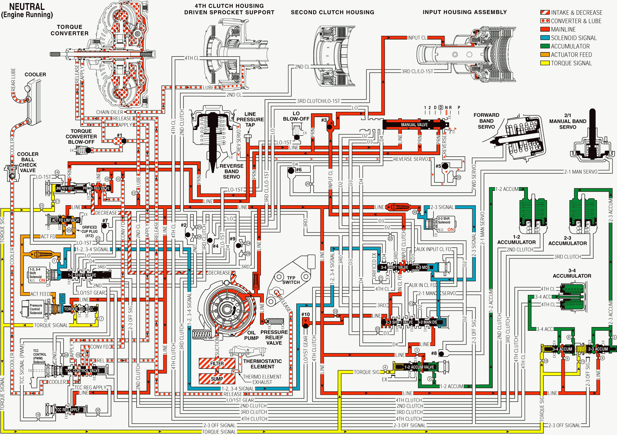
When the gear selector lever is moved from the REVERSE position to the NEUTRAL position the following changes occur to the hydraulic and electrical systems.
Manual Valve (404)
The manual valve is moved to the NEUTRAL position and blocks line pressure from entering the Reverse fluid circuit. The reverse fluid circuit is opened to an exhaust at the manual valve.
Reverse Band Assembly (615)
Reverse fluid exhausts from the reverse servo, the #5 ball check valve unseats, allowing reverse servo fluid to quickly exhaust at the manual valve, and the reverse band releases, shifting the transmission into NEUTRAL.
Pressure Regulator Valve (313) (Torque Converter/Cooler and Lube Circuits)
Line pressure at the valve enters the converter feed circuit which is then routed to the TCC control valve.
TCC Control Valve (335)
Spring pressure holds the valve in the released position. Converter feed fluid is directed to the release circuit. Release fluid seats #1 ball check valve and feeds the TCC blow-off. Release fluid feeds the TCC on the cover side of the pressure plate, exits the TCC through the apply circuit, then feeds the cooler circuit at the TCC control valve. Cooler fluid passes through the ball check valve, through the cooler, then returns to the transmission and feeds the rear lube circuit. A front lube circuit is fed from orificed line pressure.
Neutral - Engine Running - Without Touch Activated Power

Park or Neutral - Engine Running Neutral - With Touch Activated Power
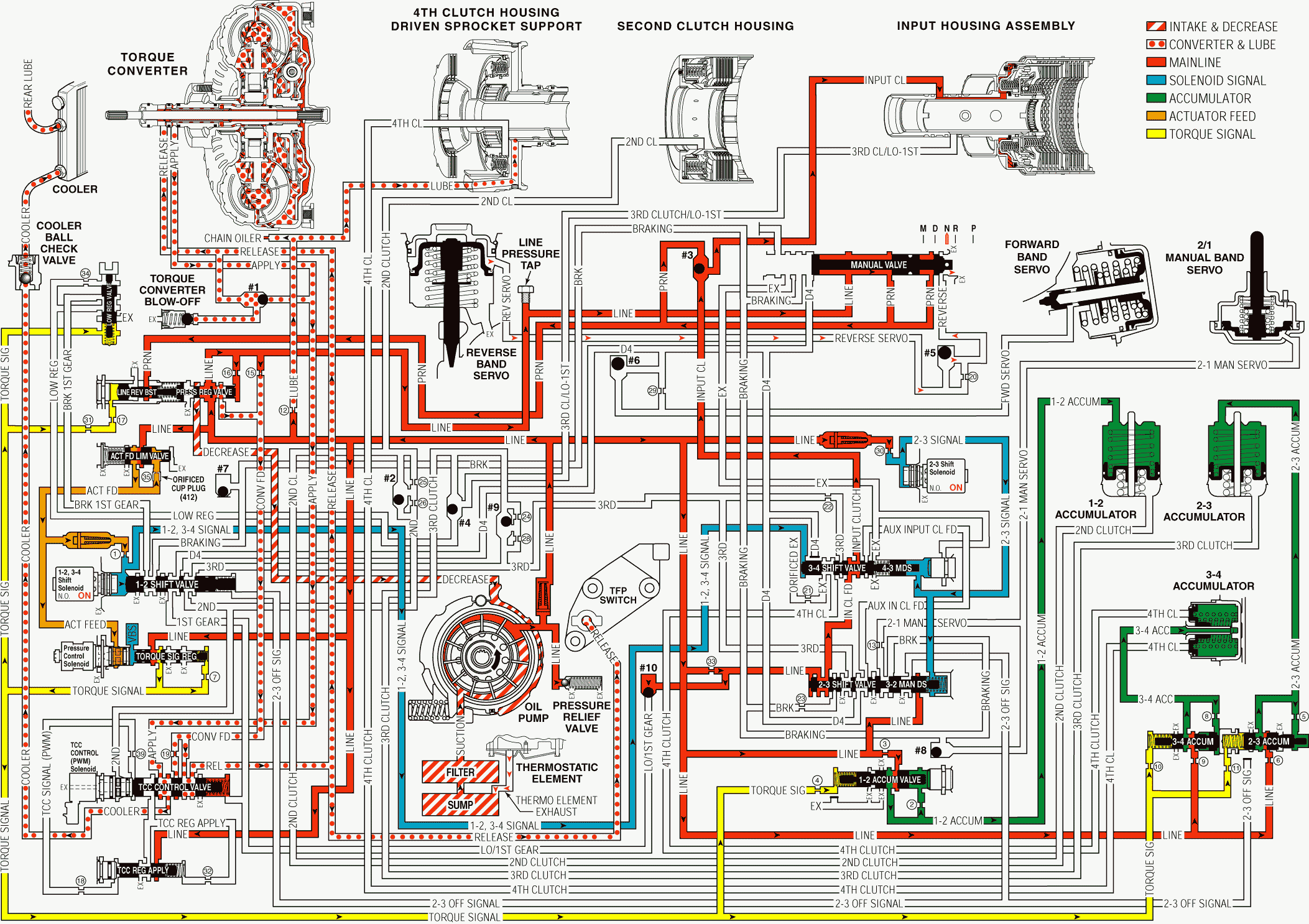
When the gear selector lever is moved from the REVERSE position to the NEUTRAL position the following changes occur to the hydraulic and electrical systems.
Manual Valve (404)
The manual valve is moved to the NEUTRAL position and blocks line pressure from entering the Reverse fluid circuit. The reverse fluid circuit is opened to an exhaust at the manual valve.
Reverse Band Assembly (615)
Reverse fluid exhausts from the reverse servo, the #5 ball check valve unseats, allowing reverse servo fluid to quickly exhaust at the manual valve, and the reverse band releases, shifting the transmission into NEUTRAL.
Pressure Regulator Valve (313) (Torque Converter/Cooler and Lube Circuits)
Line pressure at the valve enters the converter feed circuit which is then routed to the TCC control valve.
TCC Control Valve (335)
Spring pressure holds the valve in the released position. Converter feed fluid is directed to the release circuit. Release fluid seats #1 ball check valve and feeds the TCC blow-off. Release fluid feeds the TCC on the cover side of the pressure plate, exits the TCC through the apply circuit, then feeds the cooler circuit at the TCC control valve. Cooler fluid passes through the ball check valve, through the cooler, then returns to the transmission and feeds the rear lube circuit. A front lube circuit is fed from orificed line pressure.
Neutral - Engine Running - With Touch Activated Power

