Removal Procedure
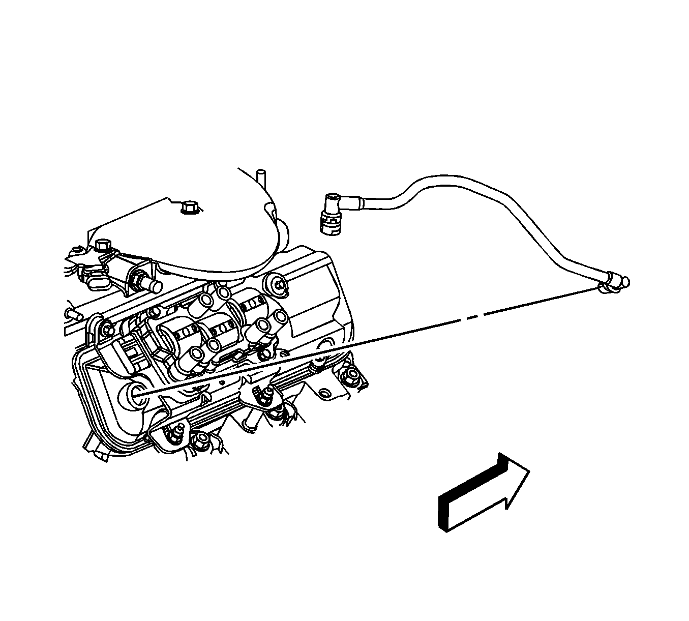
- Disconnect the negative battery cable. Refer to
Battery Negative Cable Disconnection and Connection .
- Remove the intake manifold cover. Refer to
Intake Manifold Cover Replacement .
- Drain the cooling system. Refer to
Cooling System Draining and Filling .
- Remove the positive crankcase ventilation (PCV) fresh air tube. Refer to
Plastic Collar Quick Connect Fitting Service .
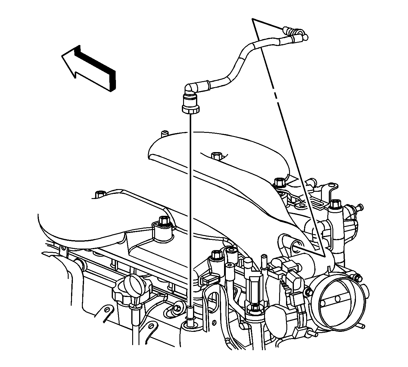
- Remove the PCV foul air tube. Refer to
Plastic Collar Quick Connect Fitting Service .
- Reposition the brake booster vacuum hose clamp at the intake manifold.
- Remove the vacuum hose from the intake manifold.
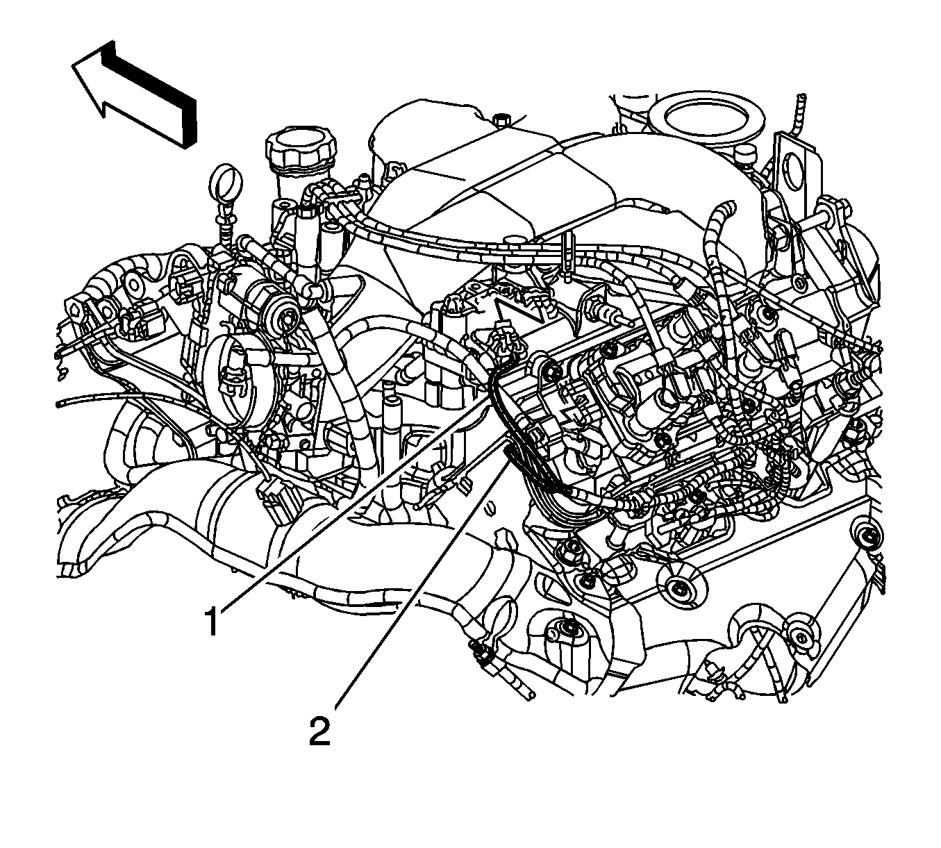
- Disconnect the engine harness electrical connector (1) from the manifold absolute pressure (MAP) sensor.
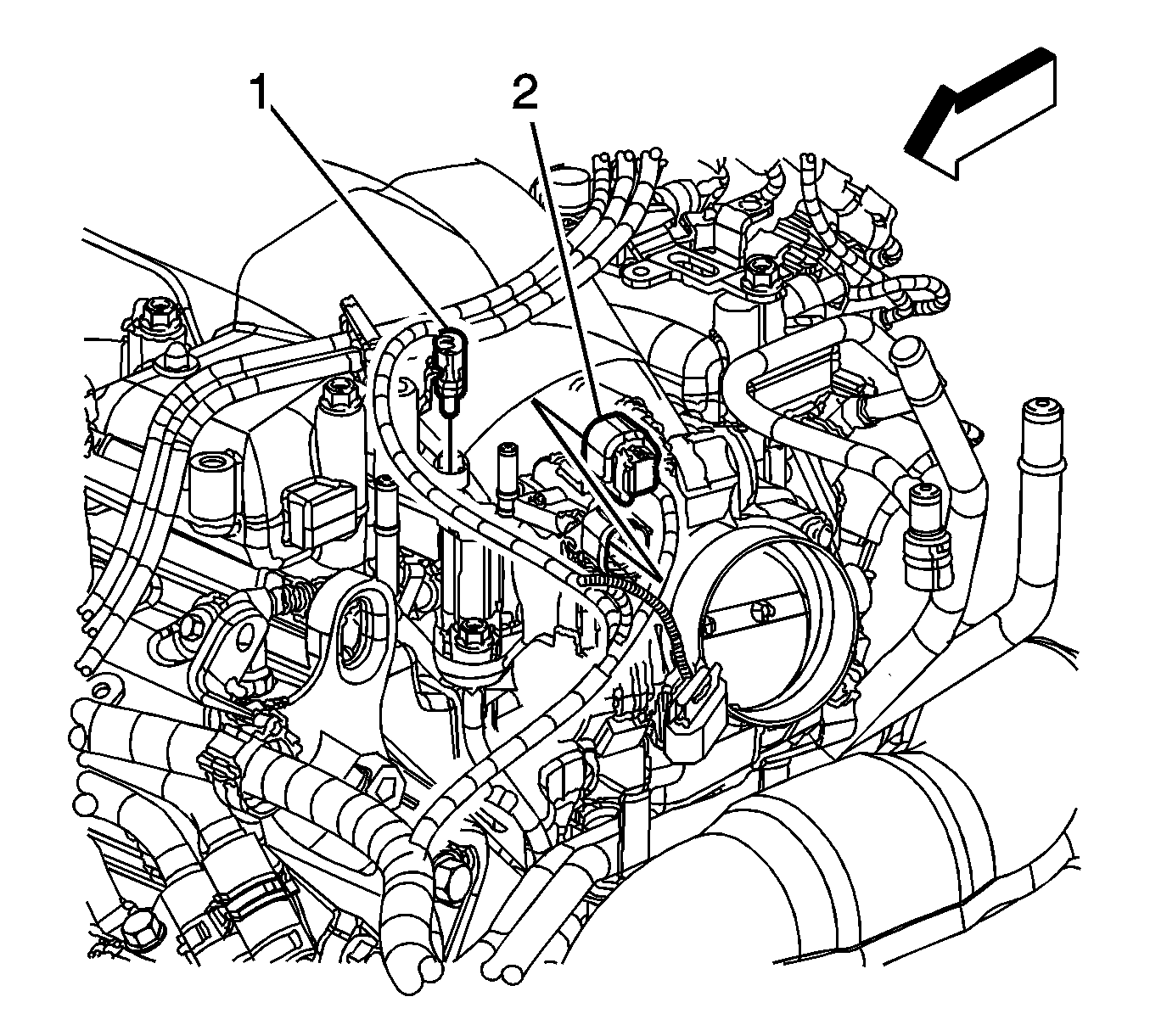
- Disconnect the engine harness electrical connectors (1, 2) from the following: electrical connector (1).
| • | The evaporative emission (EVAP) canister purge solenoid |
| • | The electronic throttle control (ETC) |
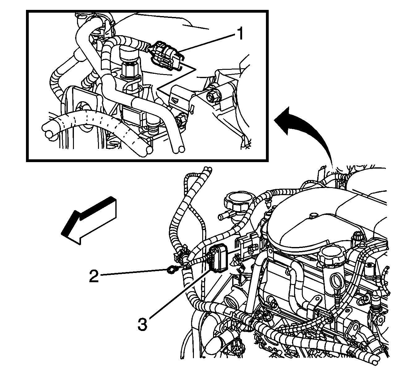
- Disconnect the engine harness electrical connector (1) from the intake manifold tuning valve.
- Remove the air cleaner outlet duct. Refer to
Air Cleaner Outlet Duct Replacement .
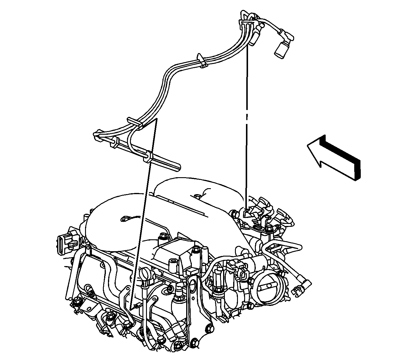
- Disconnect the left side spark plug wires from the spark plugs.
- Disconnect the left side spark plug wires from the ignition control module.
- Disengage the spark plug wire retainer clips from the intake manifold bracket and the heater inlet/outlet pipe.
- Remove the left side spark plug wires.
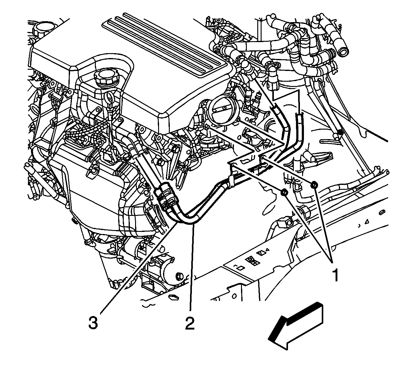
- Remove the heater inlet and outlet pipe nuts (1) from the throttle body studs.
- Remove the inlet and outlet pipe from the studs.
- Remove the nut from the generator bracket to the intake manifold.
- Remove the bolt connecting the generator to the bracket and the generator to the intake manifold.
- Remove the bracket.
- Remove the bolt holding the transmission dipstick tube to the upper intake manifold.
- Remove the ignition coils. Refer to
Ignition Coil Replacement .
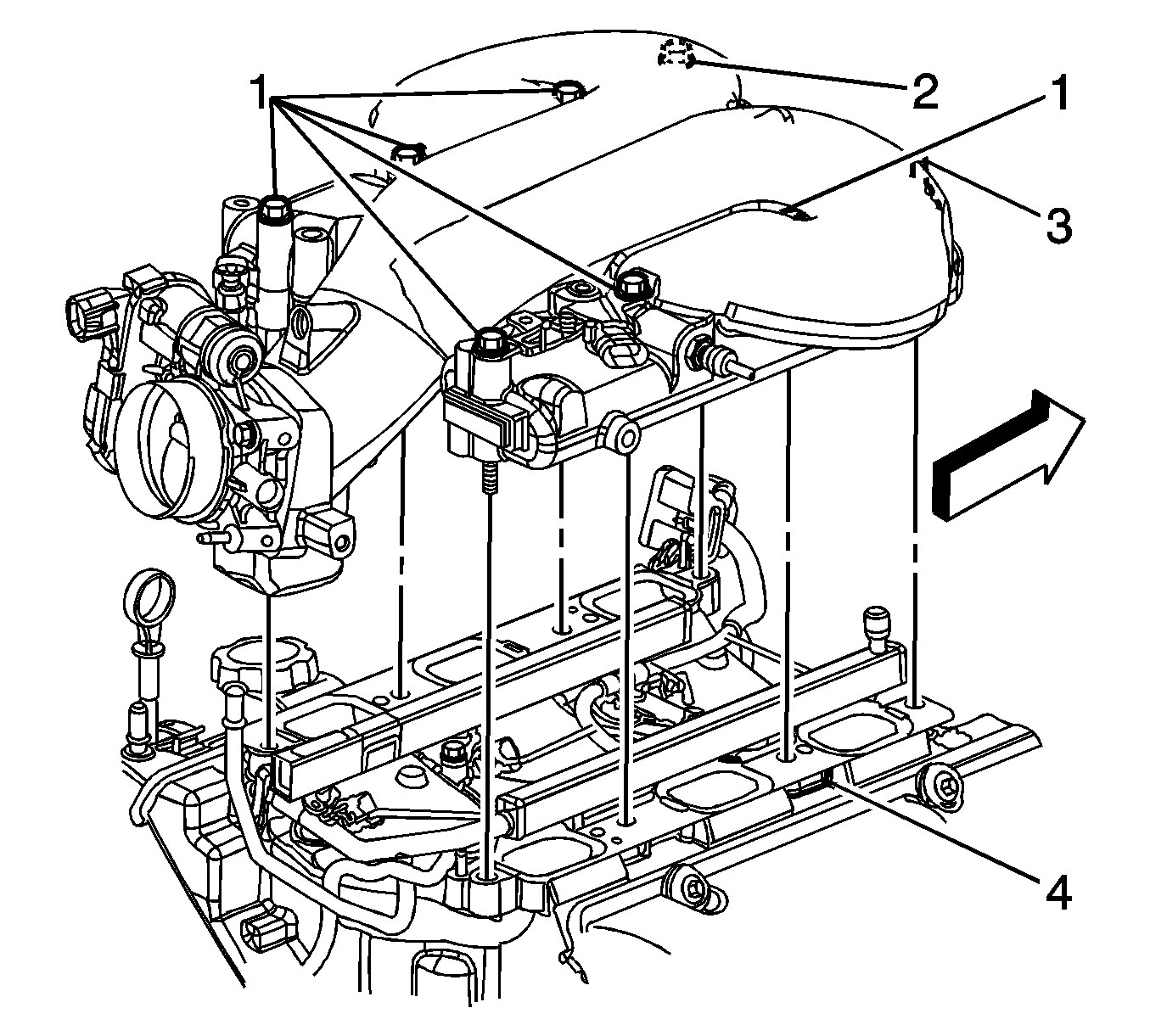
- Remove the upper intake manifold bolts (1, 2) and stud (3).
- Separate and remove the upper intake manifold from the lower intake manifold.
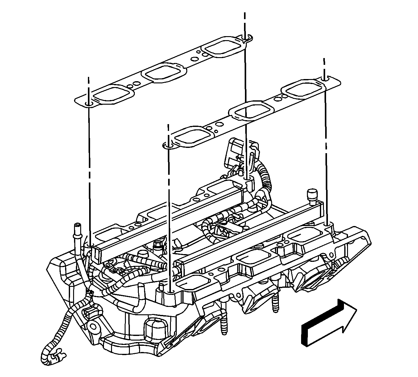
- Remove the upper to lower intake manifold gaskets.
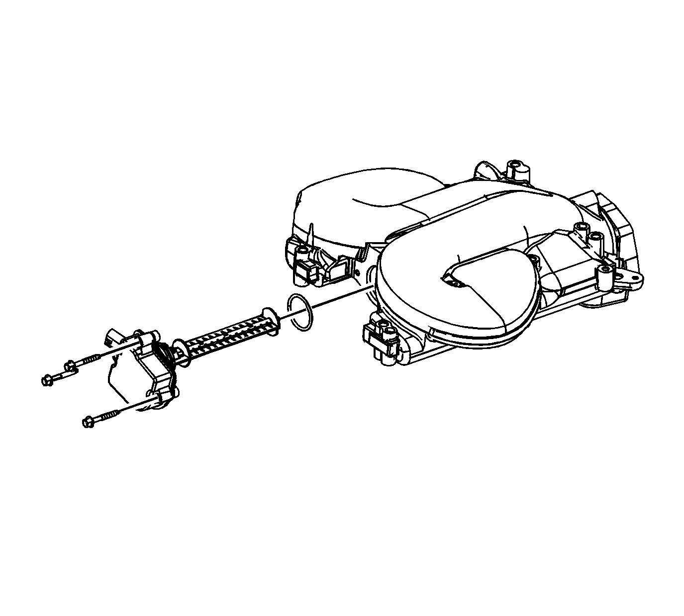
- Remove the inlet manifold tuning valve bolts and valve.
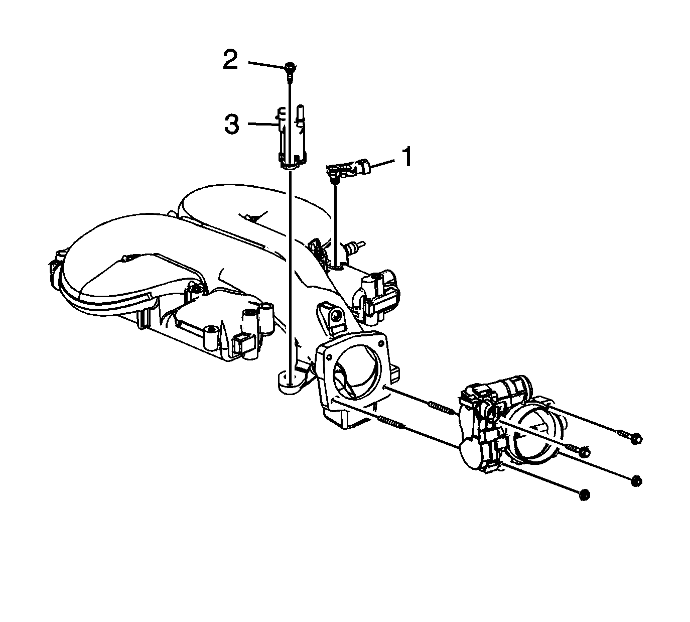
- Remove the EVAP canister purge solenoid valve bolt (2) and valve (3).
- Remove the MAP sensor bracket bolts, bracket and sensor (1).
- Remove the throttle body bolts/studs and throttle body.
- Clean the upper intake to lower intake gasket mating surfaces.
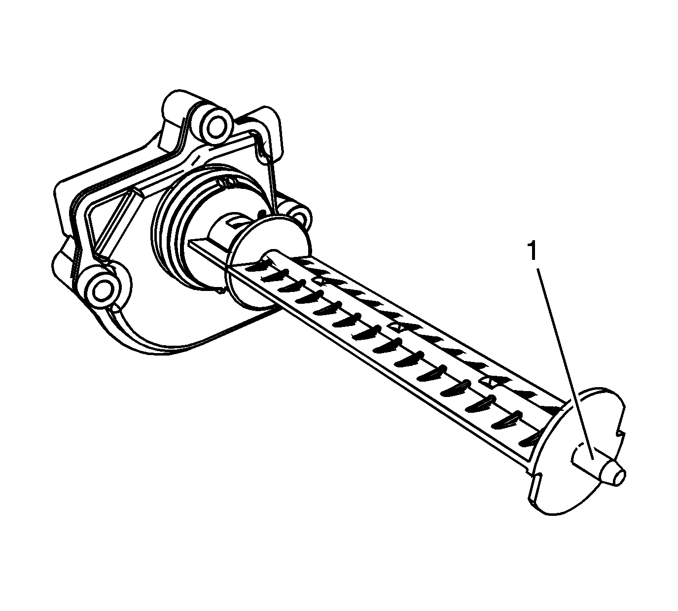
- Inspect the intake manifold tuning valve seal for damage. The tuning valve blade attachment to the motor should be tight, with no looseness or slack present. Replace as necessary.
- Apply lubricant to the nose of the valve blade (1). Refer to
Adhesives, Fluids, Lubricants, and Sealers .
Installation Procedure
Caution: Refer to Fastener Caution in the Preface section.

- Install the inlet manifold tuning valve, and bolts. Tighten the bolts to
10 N·m (89 lb in)
.

- Inspect the EVAP canister purge solenoid valve seal for damage, replace as necessary.
- Install the EVAP canister purge solenoid valve (3) and bolt (2). Tighten the bolt to
16 N·m (12 lb ft)
.
- Inspect the MAP sensor seal for damage, replace as necessary.
- Install the MAP sensor (1), bracket, and bolts.
- Inspect the throttle body seal for damage. Replace as necessary.
- Apply threadlocker to the throttle body bolts/studs threads. Refer to
Adhesives, Fluids, Lubricants, and Sealers .
- Install the throttle body and bolts/studs. Tighten the bolts/studs to
10 N·m (89 lb in)
.

- Install the NEW upper to lower intake manifold gaskets.

- Set the upper intake manifold onto the lower intake manifold.
- Apply threadlocker to the upper intake manifold bolts/stud threads. Refer to
Adhesives, Fluids, Lubricants, and Sealers .
- Install the upper intake manifold bolts (1, 2) and stud (3). Tighten the bolts and stud to
25 N·m (18 lb ft)
.

- Install the ignition coil. Refer to
Ignition Coil Replacement .
- Reposition the transmission tube and install the bolt at the intake manifold.
- Install the bracket from the generator to the intake manifold.
- Install the bolt connecting the generator, bracket and the intake manifold.
- Install the nut connecting the generator bracket to the upper intake manifold.
- Install the inlet and outlet pipe to the studs.
- Install the heater inlet and outlet pipe nuts (1) to the throttle body studs. Tighten the nuts to
10 N·m (89 lb in)
.

- Install the left side spark plug wires.
- Connect the left side spark plug wires to the spark plugs.
- Connect the left side spark plug wires to the ignition control module.
- Engage the spark plug wire retainer clips to the intake manifold bracket and the heater inlet/outlet pipe.
- Install the air cleaner outlet duct. Refer to
Air Cleaner Outlet Duct Replacement .

- Connect the engine harness electrical connector (1) to the intake manifold tuning valve.

- Connect the engine harness electrical connectors (1, 2) to the following:
| • | The EVAP canister purge solenoid |

- Connect the MAP sensor electrical connector (1).
- Install the brake booster vacuum hose to the intake manifold.
- Position the vacuum hose clamp at the intake manifold.

- Install the PCV foul air tube. Refer to
Plastic Collar Quick Connect Fitting Service .

- Install the PCV fresh air tube. Refer to
Plastic Collar Quick Connect Fitting Service .
- Fill the cooling system. Refer to
Cooling System Draining and Filling .
- Install the intake manifold cover. Refer to
Intake Manifold Cover Replacement .
- Connect the negative battery cable. Refer to
Battery Negative Cable Disconnection and Connection .


