For 1990-2009 cars only
Removal Procedure
- Open and support the hood.
- Disconnect the negative battery cable. Refer to Battery Negative Cable Disconnection and Connection .
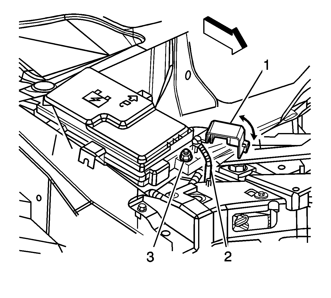
- Remove the cover (1) from the base (6) of the accessory wiring junction block assembly.
- Remove the positive battery cable nut (3) and disconnect the cable (2) from the positive terminal stud.
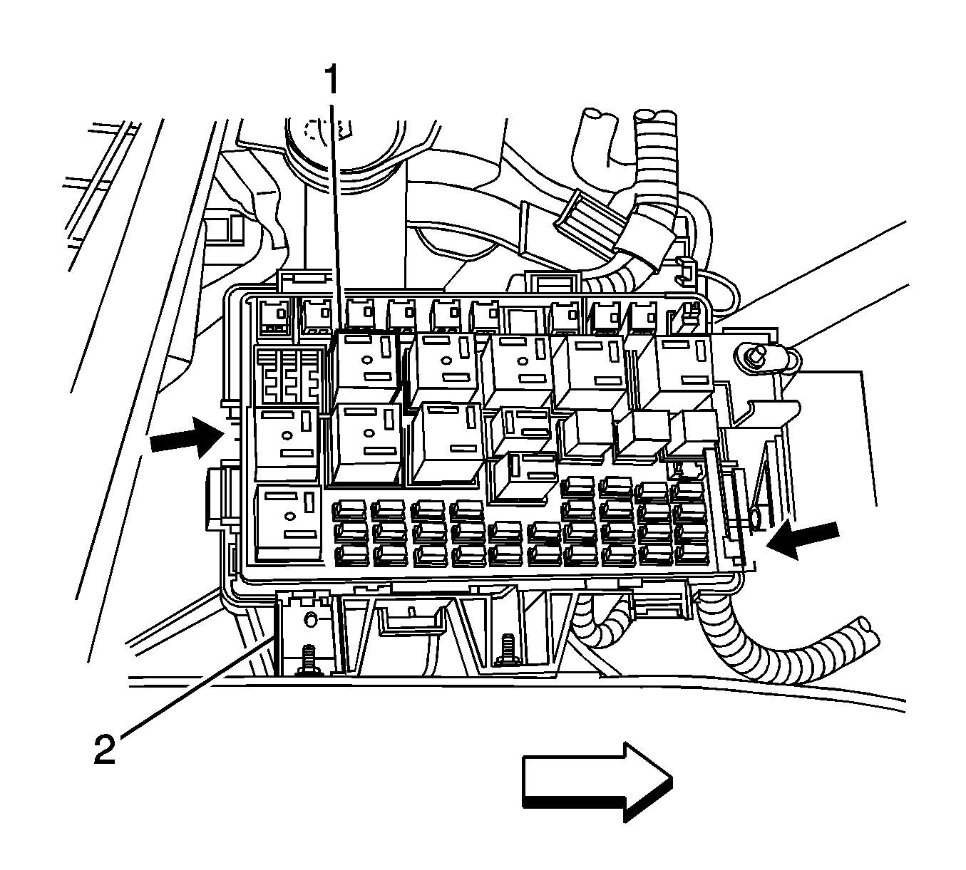
- Release the 2 locking tabs from the base side as indicated by the arrows of the electrical center (1), as shown.
- Carefully lift at each side of the underhood accessory wiring junction block assembly in order to release the underhood accessory wiring junction block assembly from the 3 main body harness connectors (1) and exposing the lower connectors.
- Remove the underhood accessory wiring junction block assembly from the vehicle.
- Use the hook tool to pull the connector (1) upward in order to secure the connectors into the base.
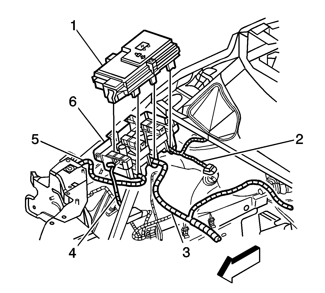
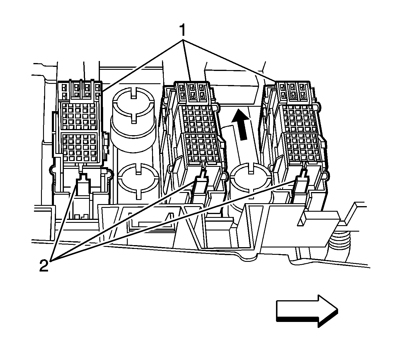
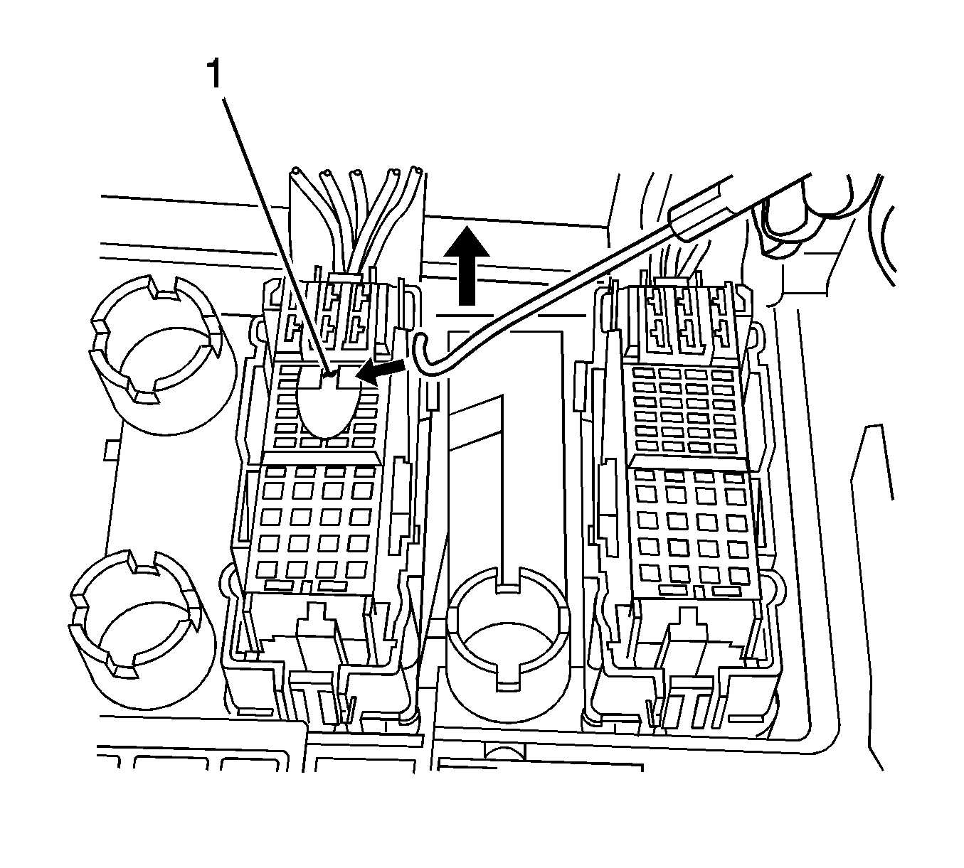
Note: Using a hook-type tool, as shown, re-stage all 3 lower harness connectors into the lower base prior to installing the new underhood accessory wiring junction block assembly.
Installation Procedure
- Verify that all 3 connectors (1) are secured to the base by applying light downward pressure to each connector and verifying the tabs are locked (2) on each side of the connector.
- Position the new underhood accessory wiring junction block assembly over the top of the base and align the locator pins to the underhood accessory wiring junction block assembly base.
- Once aligned, apply downward pressure to the new underhood accessory wiring junction block assembly in order to secure the top half to the base.
- Inspect the 2 outer locking tabs to ensure the new underhood accessory wiring junction block assembly is locked into the lower base (2).
- Install the positive battery cable (2) over the stud and install the retaining nut (3) and tighten to 10 N·m (89 lb in) .
- Install the underhood electrical center cover (1) to the electrical center base (6).
- Connect the negative battery cable. Refer to Battery Negative Cable Disconnection and Connection .
- Close the hood.
- Perform the power sliding door re-initialization procedure. Refer to Rear Side Door Actuator Control Module Programming and Setup .


Caution: Refer to Fastener Caution in the Preface section.


