Power Sliding Door Motor Clutch Replacement RPO E59
Removal Procedure
- Disable the PSD system by removing the PSD 15A fuse from the instrument panel (I/P) fuse block.
- Remove the left body side trim panel. Refer to Body Side Front Trim Panel Replacement - Left Side .
- Open the sliding door 1/3 of the way.
- Support the bottom of the sliding door.
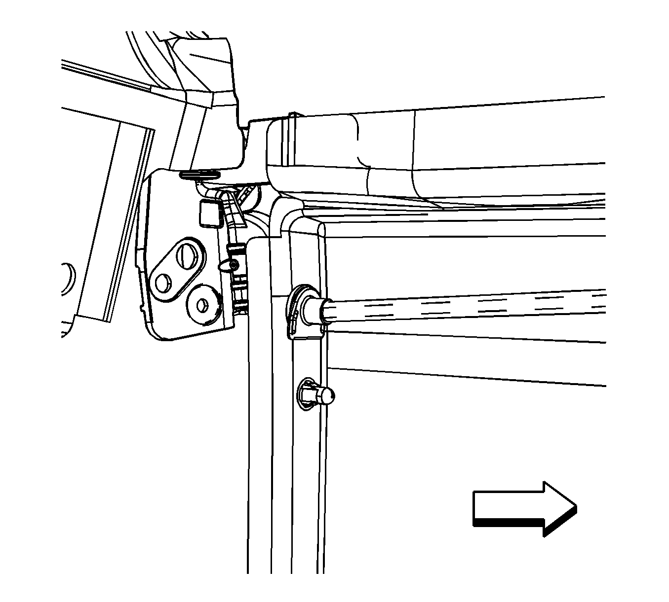
- Remove the center roller bracket pin. Separate the center roller bracket, body side, from the center roller bracket, door side.
- Position the bottom of the sliding door out at the rear in order to provide access to the center roller bracket, body side.
- Remove the sliding door center track cover. Refer to Rear Side Door Center Track Cover Replacement .
- Position the sliding door center roller bracket, body side, at the front of the center roller track.
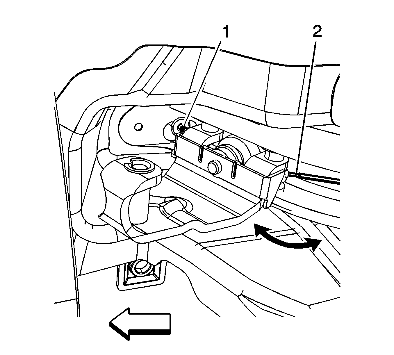
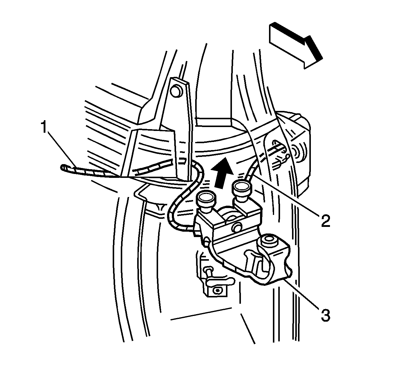
- Manually pull the forward cable (1) in order to release the cable barrel from the sliding door bracket.
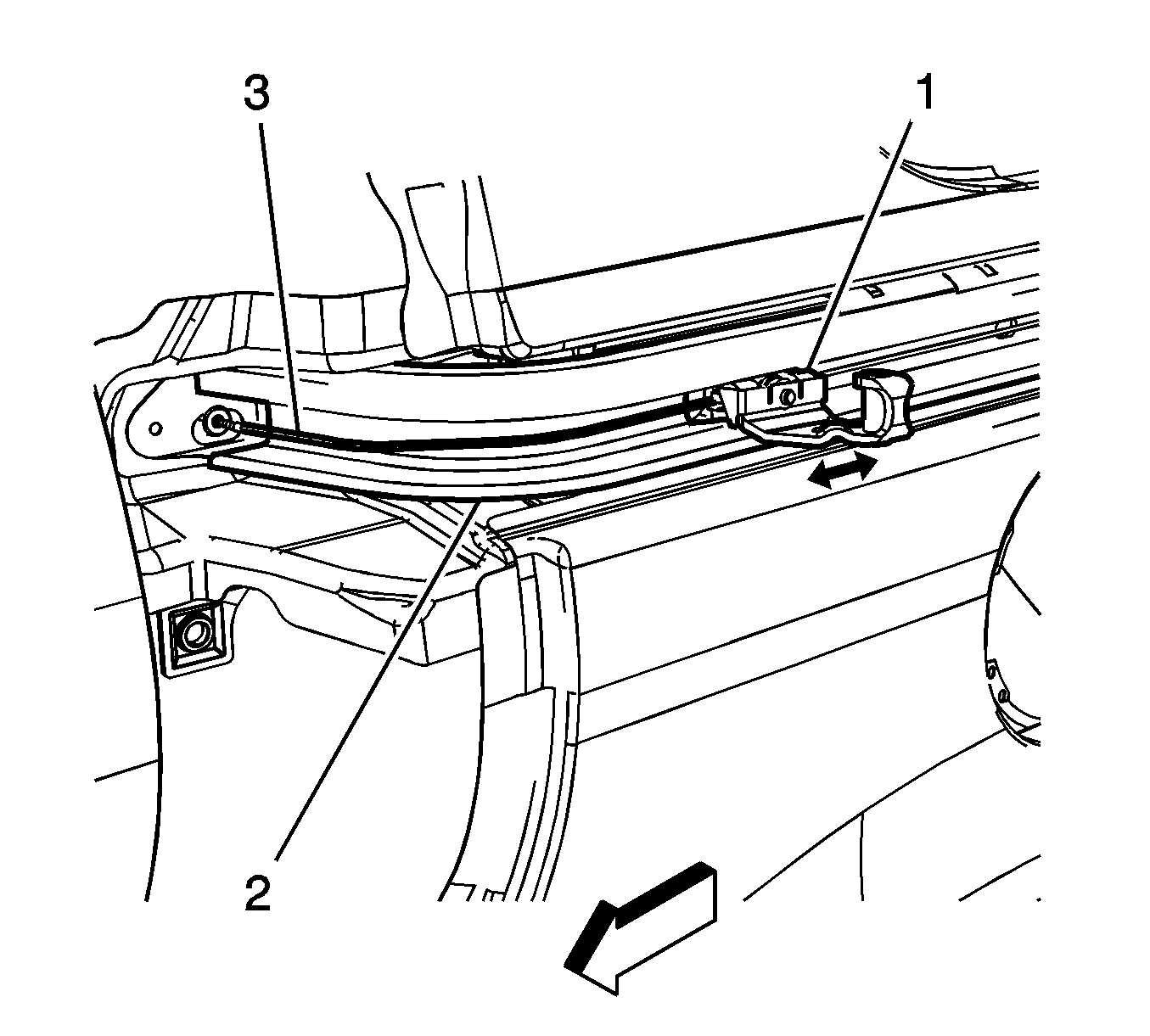
- Lift the center roller bracket (1), body side, up and out from the front radius of the sliding door center track (2).
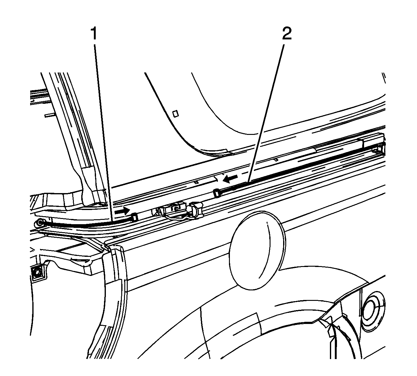
- Detach the cable end (1, 2) from the sliding door center roller bracket, body side.
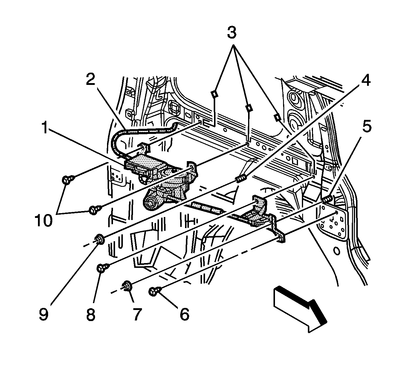
- Remove the front pulley bolts (6, 8).
- Remove the front pulley nut (7).
- Remove the front pulley from the front inner quarter panel.
- Remove the rear pulley bolts.
- Remove the rear cable (2) from the opening at the rear of the sliding door center track.
- Remove the rear pulley from the rear inner quarter panel.
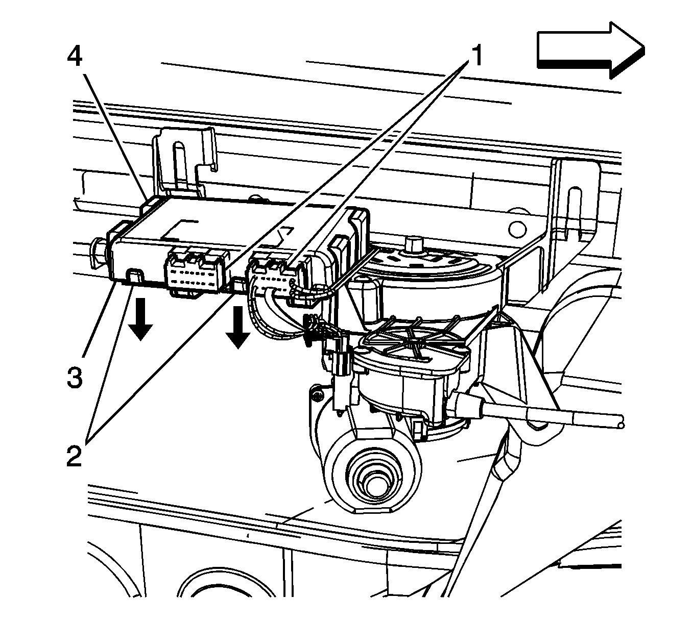
- Disconnect the wiring harness connectors (1) from the actuator control module (3).
- Remove the motor clutch assembly nuts (9).
- Remove the motor clutch assembly bolts (10).
- Carefully remove the motor clutch assembly from the vehicle.
Note: By removing the power sliding door (PSD) 15A fuse, the low current logic power for both the LH and RH power sliding door modules (PSDM) will be interrupted and both PSDs will be inoperative.
Caution: Use care when feeding cables to and from the center track and body to avoid damage to the coated cables and the vehicle's painted surface.
Note: Note the routing of the cables to ensure the new cables are correctly seated.
Installation Procedure
- Ensure the J-clips (3) are secured to the inner body panel prior to installing the motor clutch assembly.
- Position the motor clutch assembly to the vehicle.
- Install the motor clutch assembly bolts (10) and tighten to 10 N·m (89 lb in) .
- Install the motor clutch assembly nuts (9) and tighten to 10 N·m (89 lb in) .
- Connect the wiring harness (1) to the actuator control module (3).
- Route the rear cable (2) through the opening in the rear sliding door center track.
- Position the rear pulley to the rear inner quarter panel.
- Install the rear pulley bolts and tighten to 10 N·m (89 lb in) .
- Install the cover (2).
- Route the front cable through the opening in the front inner quarter panel.
- Position the front pulley (2) to the front inner quarter panel.
- Install the front pulley bolts and tighten to 10 N·m (89 lb in) .
- Install the front pulley nut and tighten to 10 N·m (89 lb in) .
- Adjust the cable tension. Refer to Rear Side Door Actuator Cable Tension Adjustment .
- Manually open and close the sliding door in order to verify the following:
- Install the left body side trim panel. Refer to Body Side Front Trim Panel Replacement - Left Side .
- Enable the PSD system by installing the PSD 15A fuse into the I/P fuse block.
Caution: Refer to Fastener Caution in the Preface section.


Caution: Use care when feeding cables to and from the center track and body to avoid damage to the coated cables and the vehicle's painted surface.
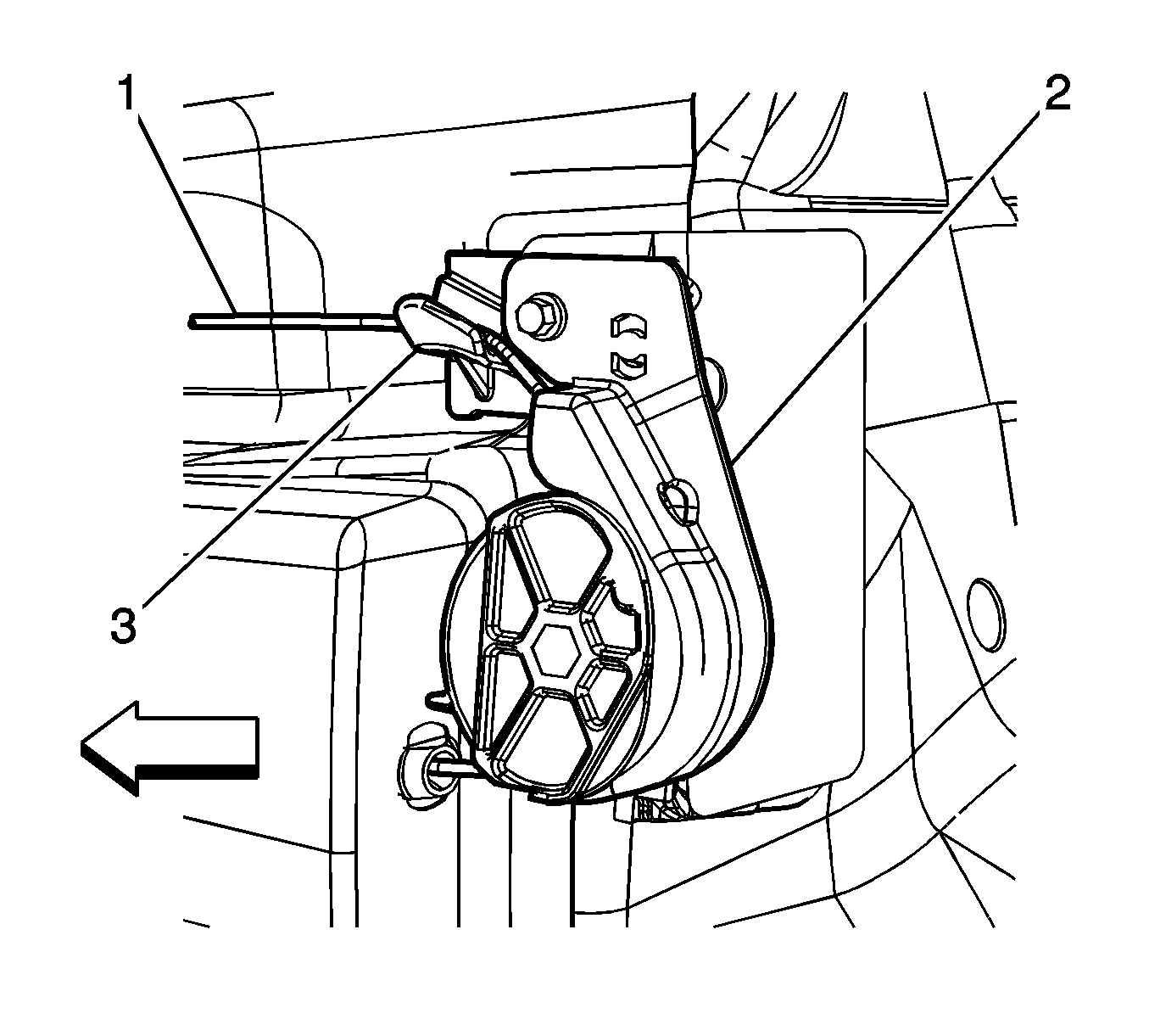

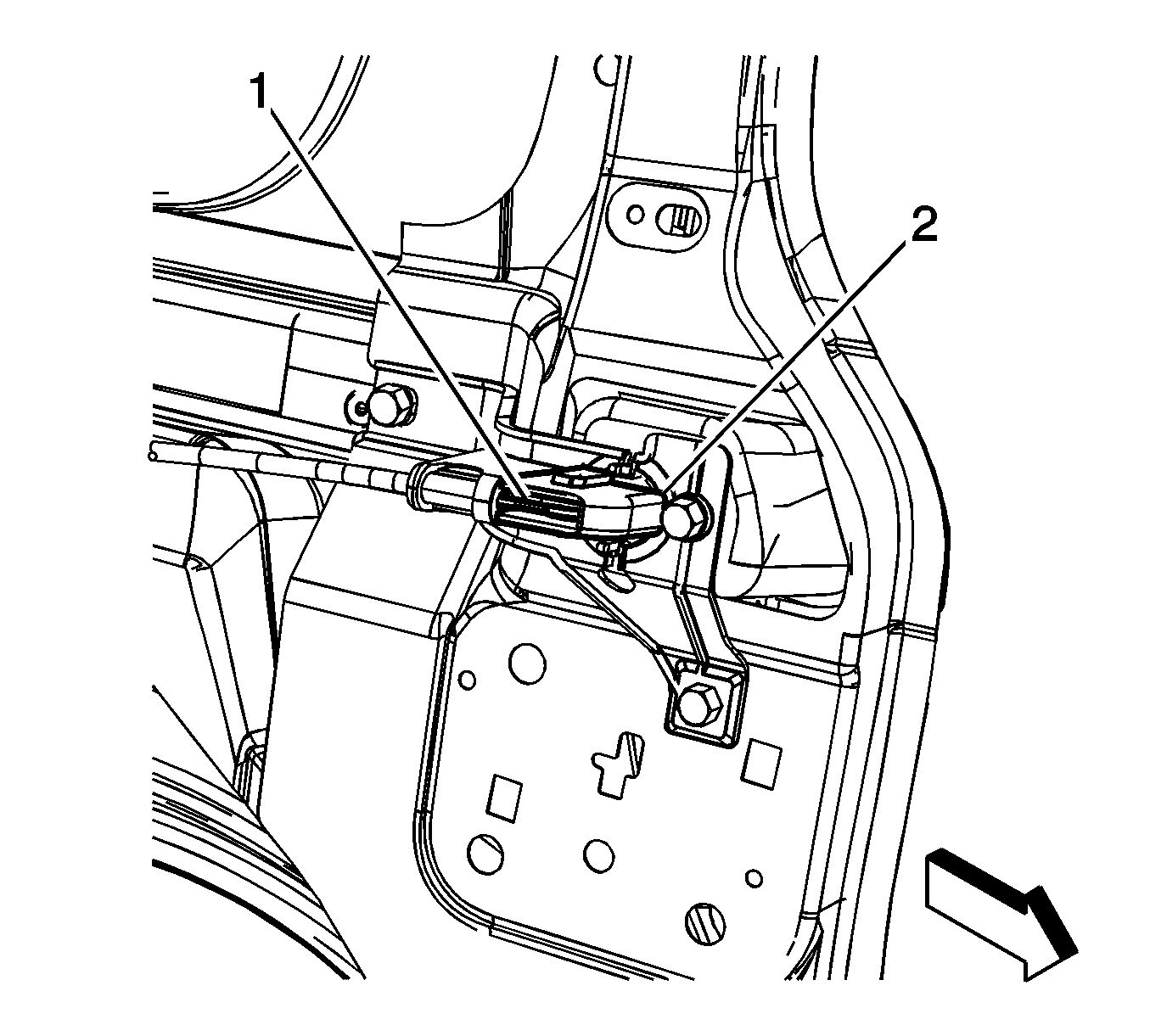
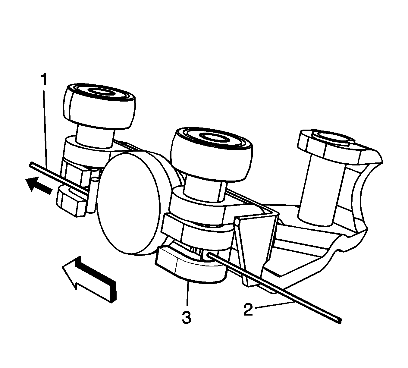
Note: Ensure that the power sliding door cable (2) barrels are properly installed into the sliding door center roller bracket, body side, cable retaining fingers located on the roller bracket (3).
| • | Latch/unlatch function operates |
| • | Cable assembly is correctly positioned in the center track |
| • | The door fits, check all external door gaps |
| • | Ensure the lower roller track is clear of any foreign material and debris. |
| • | Ensure the fuel filler door is in the closed position. |
Note: By installing the 15A fuse, the low current logic power will be restored to both the LH and RH PSDMs and the PSDs will be operational. However, both PSDMs will have to learn the full open and full closed positions of the PSD. Refer to Rear Side Door Actuator Control Module Programming and Setup .
Power Sliding Door Motor Clutch Replacement RPO E58
Removal Procedure
- Disable the PSD system by removing the PSD 15A fuse from the instrument panel (I/P) fuse block.
- Remove the right rear quarter lower trim panel. Refer to Rear Quarter Trim Panel Replacement - Right Side .
- Open the sliding door 1/3 of the way.
- Support the bottom of the sliding door.
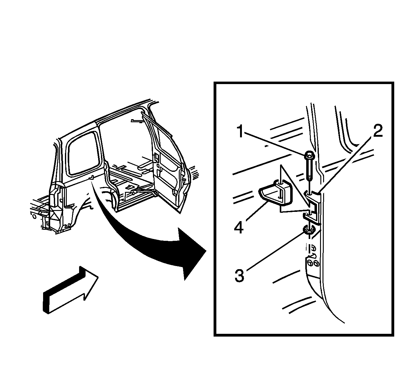
- Remove the center roller bracket pin (1). Separate the center roller bracket (4), body side, from the center roller bracket (2), door side.
- Position the bottom of the sliding door out at the rear in order to provide access to the center roller bracket (2), body side.
- Remove the sliding door center track cover. Refer to Rear Side Door Center Track Cover Replacement .
- Position the sliding door center roller bracket, body side, at the front of the center roller track.
- Manually pull the forward cable in order to release the cable barrel from the sliding door bracket.
- Lift the center roller bracket, body side, up and out from the front radius of the sliding door center track.
- Detach the cable barrel end (1) from the sliding door center roller bracket, body side.
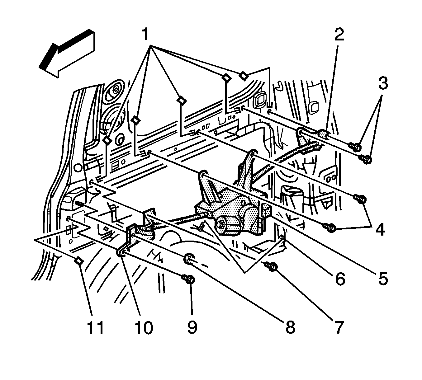
- Remove the front pulley bolts (9).
- Remove the front pulley nut (8).
- Remove the front pulley (10) from the front inner quarter panel.
- Remove the rear pulley cover (4) and bolts.
- Remove the rear pulley (3).
- Remove the rear cable from the opening at the rear of the sliding door center track.
- Remove the rear pulley from the rear inner quarter panel.
- Disconnect the wiring harness connectors from the actuator control module (3).
- Remove the motor clutch assembly nuts (6).
- Remove the motor clutch assembly bolts (4).
- Carefully remove the motor clutch assembly from the vehicle.
Note: By removing the power sliding door (PSD) 15A fuse, the low current logic power for both the LH and RH power sliding door modules (PSDM) will be interrupted and both PSDs will be inoperative.
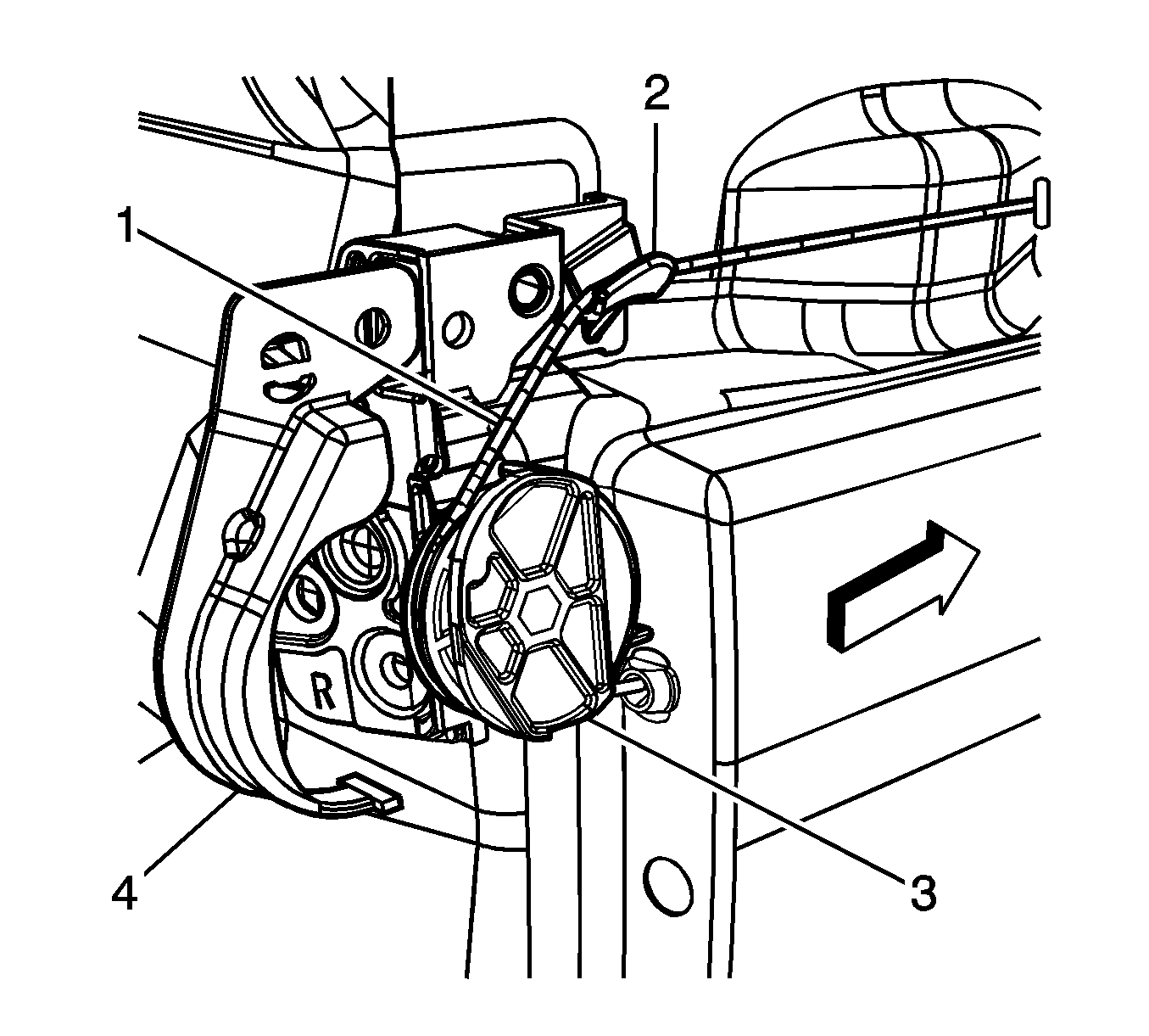
Caution: Use care when feeding cables to and from the center track and body to avoid damage to the coated cables and the vehicle's painted surface.
Note: Note the routing of the cables to ensure the new cables are properly seated.
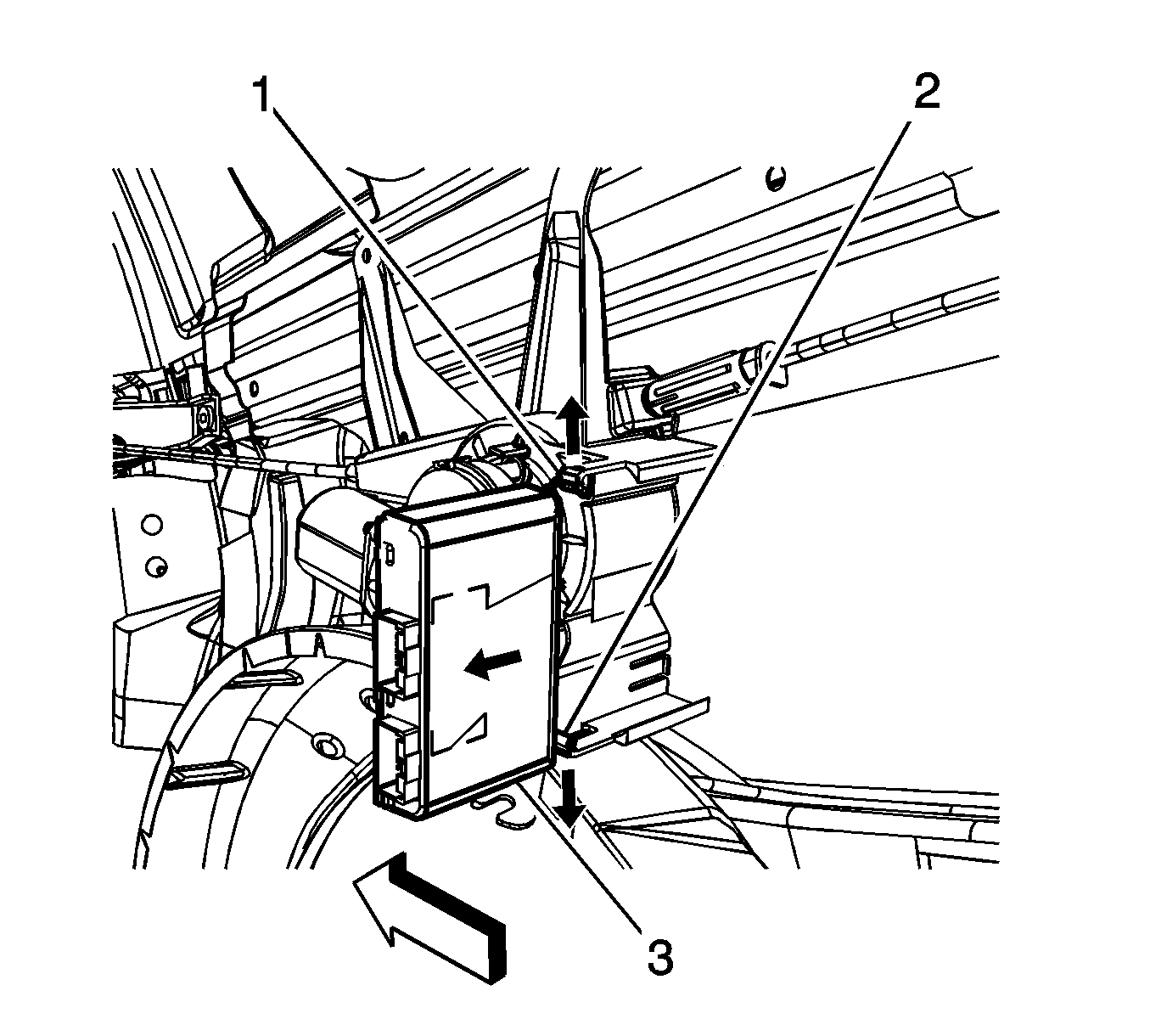

Installation Procedure
- Ensure the J-clips (1, 11) are secured to the inner body panel prior to installing the motor clutch assembly.
- Position the motor clutch assembly (5) to the vehicle.
- Install the motor clutch assembly bolts (4) and tighten to 10 N·m (89 lb in) .
- Install the motor clutch assembly nuts and tighten to 10 N·m (89 lb in) .
- Connect the wiring harness to the motor clutch assembly.
- Route the rear cable (1) through the opening in the rear sliding door center track.
- Position the rear pulley (3) to the rear inner quarter panel.
- Install the rear pulley bolts (3) and tighten to 10 N·m (89 lb in) .
- Route the front cable through the opening in the front inner quarter panel.
- Position the front pulley (10) to the front inner quarter panel.
- Install the front pulley bolts (7, 9) and tighten to 10 N·m (89 lb in) .
- Install the front pulley nut (8) and tighten to 10 N·m (89 lb in) .
- Adjust the PSD cable tension. Refer to Rear Side Door Actuator Cable Tension Adjustment .
- Manually open and close the sliding door in order to verify the following:
- Install the right rear quarter lower trim panel. Refer to Rear Quarter Trim Panel Replacement - Right Side .
- Enable the PSD system by installing the PSD 15A fuse into the I/P fuse block.
Caution: Refer to Fastener Caution in the Preface section.

Caution: Use care when feeding cables to and from the center track and body to avoid damage to the coated cables and the vehicle's painted surface.


Note: Ensure that the power sliding door cable (2) barrels are properly installed into the sliding door center roller bracket, body side, cable retaining fingers located on the roller bracket (3).
| • | Latch/unlatch function operates |
| • | Cable assembly is correctly positioned in the center track |
| • | The door fits, check all external door gaps |
| • | Ensure the lower roller track is clear of any foreign material and debris. |
Note: By installing the 15A fuse, the low current logic power will be restored to both the LH and RH PSDMs and the PSDs will be operational. However, both PSDMs will have to learn the full open and full closed positions of the PSD. Refer to Rear Side Door Actuator Control Module Programming and Setup .
