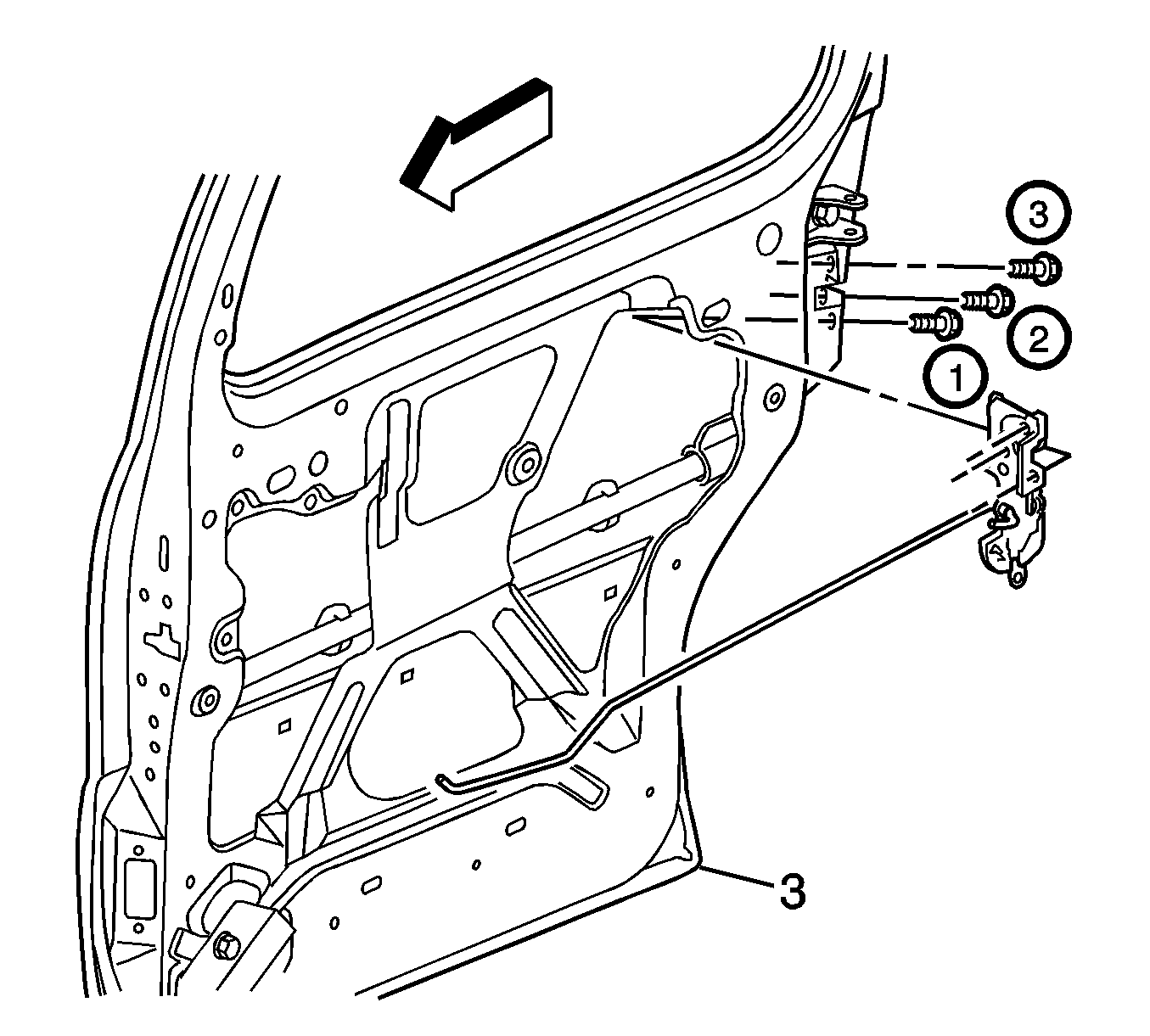
For 1990-2009 cars only
Removal Procedure
- If equipped with a power sliding door, disable the PSD system by removing the PSD 15A fuse from the instrument panel (I/P) fuse block.
- Remove the sliding door inner trim panel. Refer to Rear Side Door Trim Panel Replacement .
- Remove the sliding door water deflector. Refer to Rear Side Door Water Deflector Replacement .
- Remove the sliding door latch screws.
- When the sliding door rear lock is loose, unhook the lock rod from the sliding door rear lock.
- Disconnect the detent switch electrical connector.
- Remove the sliding door rear lock from inside the sliding door.
Note: By removing the power sliding door (PSD) 15A fuse, the low current logic power for both the LH and RH power sliding door modules (PSDM) will be interrupted and both PSDs will be inoperative.

Installation Procedure
- Position the sliding door rear lock inside the sliding door.
- Hook and secure the lock rod to the sliding door rear lock.
- Connect the detent switch electrical connector.
- Install the sliding door rear lock screws according to the specified fastener tightening sequence and tighten to 10 N·m (89 lb in) .
- Verify the operation of the lock assembly. Adjust, if needed.
- Install the sliding door water deflector. Refer to Rear Side Door Water Deflector Replacement .
- Install the sliding door inner trim panel. Refer to Rear Side Door Trim Panel Replacement .
- If equipped with a power sliding door, enable the PSD system by installing the PSD 15A fuse into the I/P fuse block.
Caution: Refer to Fastener Caution in the Preface section.

Note: By installing the 15A fuse, the low current logic power will be restored to both the LH and RH PSDMs and the PSDs will be operational. However, both PSDMs will have to learn the full open and full closed positions of the PSD. Refer to Rear Side Door Actuator Control Module Programming and Setup .
