For 1990-2009 cars only
Removal Procedure
- Remove the case side cover. Refer to Control Valve Body Cover Replacement .
- Disconnect the transaxle wiring harness.
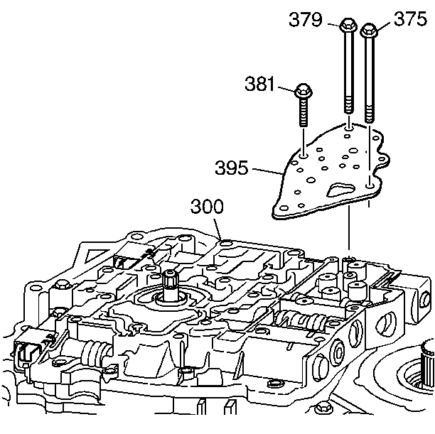
- Remove the control valve body bolts (375, 379, 381) that mount the fluid pressure manual valve position switch to the control valve body (300).
- Carefully remove the fluid pressure manual valve position switch. Handle the switch carefully, the fluid pressure manual valve position switch is very delicate.
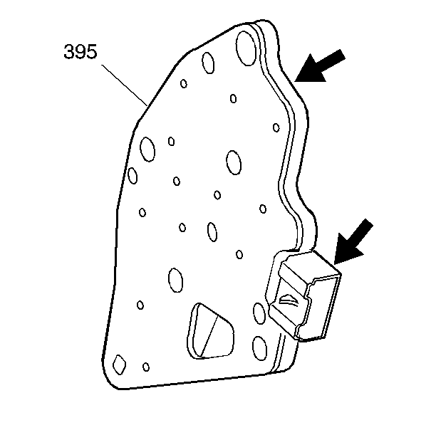
- Inspect the fluid pressure manual valve position switch (395) for the following conditions:


| • | Damaged electrical connector terminals |
| • | Damaged seals |
| • | Damaged switch membranes |
| • | Debris on the switch membranes |
Installation Procedure
- Carefully install the fluid pressure manual valve position switch. Handle the switch carefully, the fluid pressure manual valve position switch is very delicate.
- Install the control valve body bolts (375, 379, 381) that mount the fluid pressure manual valve position switch to the control valve body (300).
- Connect the transaxle wiring harness.
- Install the case side cover. Refer to Control Valve Body Cover Replacement .

Caution: Refer to Fastener Caution in the Preface section.
| • | Tighten the control valve body bolt (375) to 12 N·m (106 lb in) . |
| • | Tighten the control valve body bolt (379) to 16 N·m (12 lb ft) . |
| • | Tighten the control valve body bolt (381) to 8 N·m (70 lb in) . |
