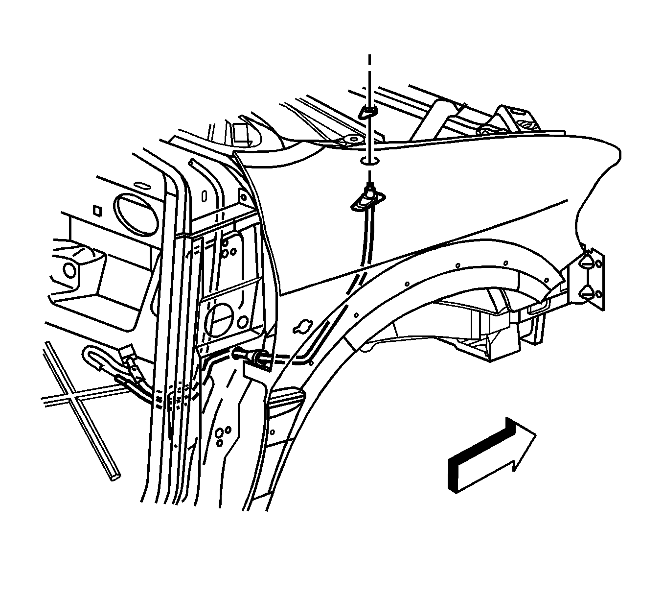
For 1990-2009 cars only
Removal Procedure
- Remove the antenna mast from the base.
- Unscrew the locking nut from the base in order to release the base from the fender.
- Remove the instrument panel insulator. Refer to Knee Bolster, Insulator, Molding Replacement - Instrument Panel in Instrument Panel, Gages, and Console.
- Remove the cowl side trim panel. Refer to Cowl Side Trim Panel Replacement in Interior Trim.
- Disconnect the antenna cable from the antenna extension lead.
- Cable is in a harness wrapped in blue tape. Note the routing of the cable.
- Remove the antenna base and cable assembly from the vehicle.

Installation Procedure
- Route the antenna base and cable assembly as noted in the removal.
- Connect the antenna cable to the antenna extension lead.
- Install the cowl side trim panel. Refer to Cowl Side Trim Panel Replacement in Interior Trim.
- Install the instrument panel insulator. Refer to Knee Bolster, Insulator, Molding Replacement - Instrument Panel in Instrument Panel, Gages, and Console.
- Tighten the locking nut in order to secure the antenna base to the fender.
- Install the antenna mast.

Notice: Refer to Fastener Notice in the Preface section.
Tighten
Tighten the nut to 5 N·m (44 lb in).
