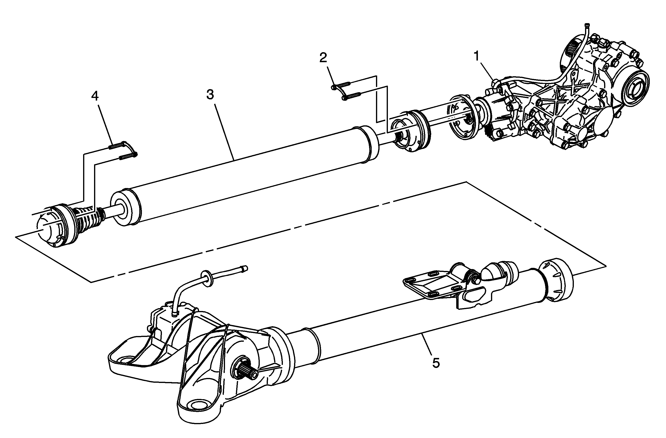
Motion/power is transferred from the engine crankshaft/flywheel through the 4T65-E automatic transaxle. A 3 gear transfer case (1), mated to the right side of the transaxle assembly, transfers torque/power to the rear differential (5) via a propeller shaft assembly (3). The front-to-rear gear ratio is 1.013:1.
Transfer Case

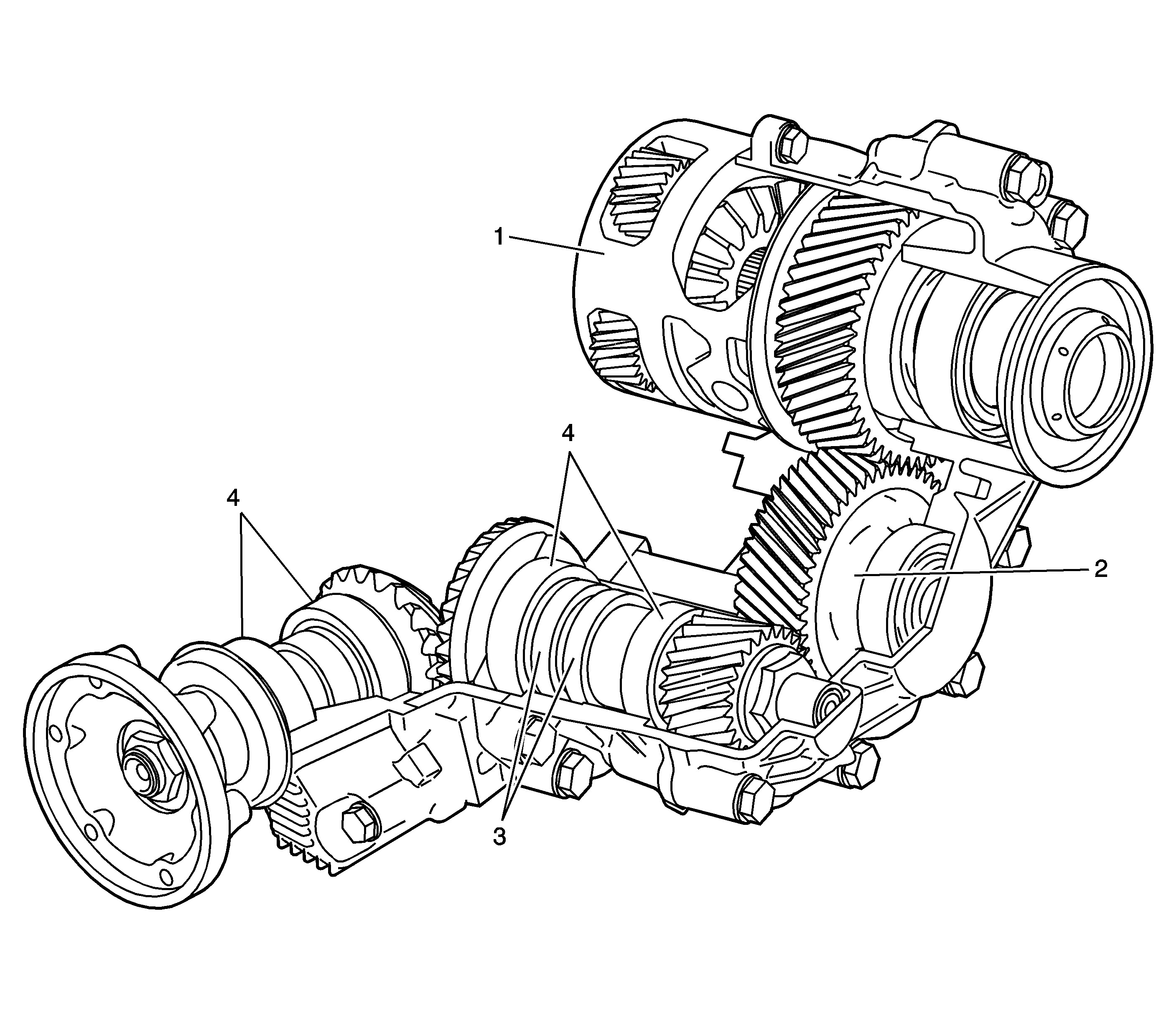
The transfer case assembly consists of a 4-piece aluminum housing, an input helical gear assembly, carrier (1), an idler helical gear (2), and a hypoid bevel gear set which consists of 2 shaft assemblies supported by tapered roller bearings (4). The design of this component changes power output from transverse to longitudinal and also positions the propeller shaft assembly near the centerline of the vehicle. The propeller shaft assembly, mated to the output flange of the transfer case, is constantly rotating and spins at a rate equal to an average of the 2 front wheels.
The transfer case is mated to the right side of the 4T65-E automatic transmission. 2 types of lubricant are used within the transfer case: automatic transmission fluid for the 3 helical gear set and a unique hypoid gear oil for the bevel gears. 2 oil seals, internal to the case (3) separate the 2 types of fluid.
Propeller Shaft

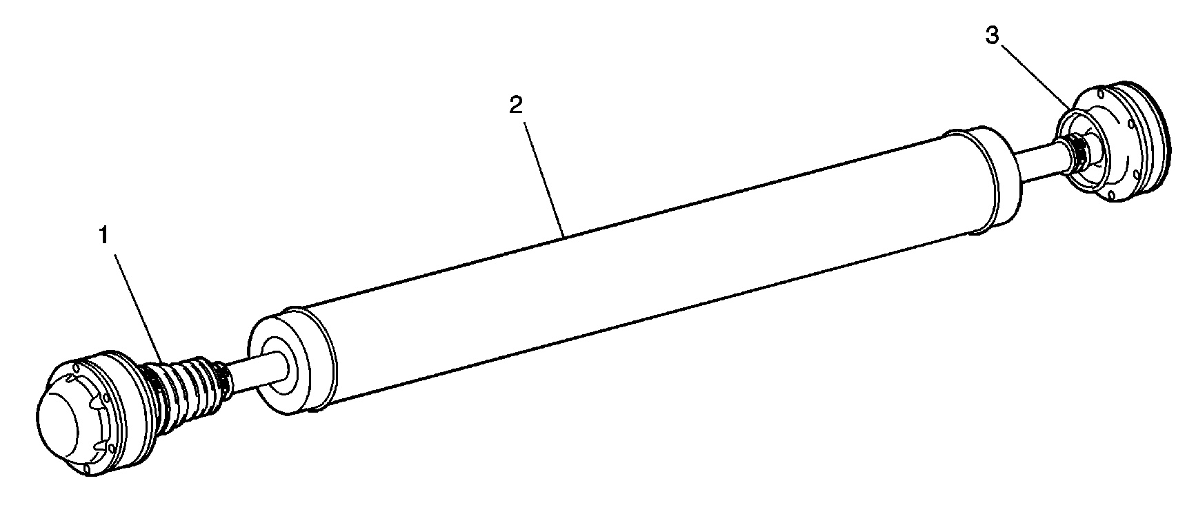
The propeller shaft assembly consists of a 1-piece aluminum tube (2) and front and rear constant velocity type joints (1 and 3). The rear constant velocity joint (1) is a plunging type design and will plunge forward and rearward as required. Dust boots, at each joint, contain the joint lubricating grease and protect the components from dirt and debris. The propeller shaft assembly is retained to the transfer case output flange and the rear differential input flange by retaining bolts.
Rear Differential

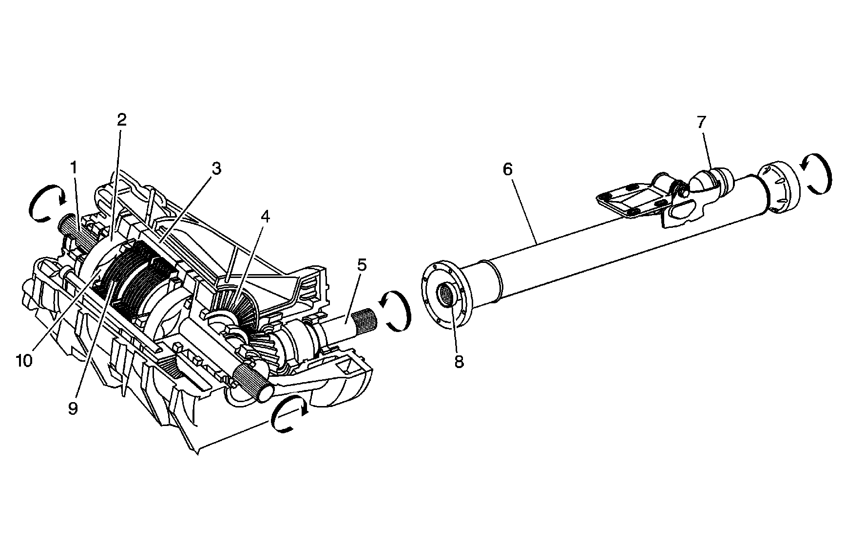
The rear differential assembly consists of a torque tube assembly (6), 3-piece differential housing, ring and pinion (4 and 5), and a differential carrier assembly (3).
The aluminum torque tube housing (6) contains an internal drive shaft (8) that is supported by roller bearings at each end. The internal drive shaft is retained to the front propeller shaft assembly by bolts and splined to the differential pinion shaft. External to the tube are a vehicle mounting bracket and a noise and vibration dampener (7).
The pinion shaft (5) is positioned in an aluminum pinion housing and is supported by tapered roller bearings. A shim between the pinion and differential housings provides the proper backlash for the ring and pinion. The ring gear (4) is retained externally to the differential carrier assembly (3) by bolts. Both the transfer case hypoid gears and the rear differential assembly use a unique type synthetic gear oil.
The differential carrier assembly (3) consists of a left and right side clutch pack drum, separate left and right axle sub shafts (1), left and right gerotor pump components (2 and 10), left and right clutch packs (9), left and right pistons, and internal valves.
The Versatrak® on-demand system operates as follows: The propeller shaft assembly, mated to the output flange of the transfer case, is constantly rotating and spins at a rate equal to an average of the 2 front wheels. Under normal straight-ahead non-slip driving conditions, the external (2) and internal (10) gears of the differential gerotor pumps are rotating at an equal rate of speed. Under those conditions, there is no speed differential between the pump gears, no pump pressure created, no clutch pack activation, and no torque transfer. During a front-wheel slip condition, the external gears (2) of the gerotor pumps rotate at a faster rate of speed than the rear-wheel driven internal gears (10). The gerotor pumps pull oil from the sump through the clutch pump check valve sending pressurized oil to each individual piston to activate the separate clutch packs. On-demand torque/drive is provided to each of the rear wheels as required. A valve internal to each piston housing controls maximum clutch pack pressure. A second valve within each housing is temperature compensating and controls fluid flow based on ambient temperature. The system operates in both forward and rearward vehicle directions.
In the event, a spare wheel of a smaller diameter is used on any of the 4 positions, the wheel rotational speed difference is detected by the wheel speed sensors of the anti-lock brake system (ABS) system. The powertrain control module (PCM) directs the clutch pump check valve to close and block oil flow to the gerotor pumps. The clutch pump check valve also monitors the sump oil for an overtemperature condition. If differential oil temperature exceeds 110°C (230°F), the valve will also close and block oil flow to the gerotor pumps. In both spare wheel usage and overtemperature conditions, a closed valve will alert the PCM to illuminate the control panel AWD Disable light.
