For 1990-2009 cars only
Tools Required
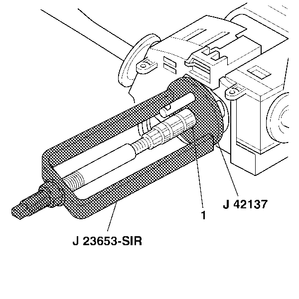
| • | J 23653-SIR Steering Column Lock Plate Compressor |
| • | J 42137 Cam Orientation Plate Adapter |
Removal Procedure
- Disconnect the battery negative cable. Refer to Battery Negative Cable Disconnection and Connection in Engine Electrical.
- Disable the SIR system. Refer to Disabling the SIR System in SIR.
- Remove the inflator module. Refer to Inflatable Restraint Steering Wheel Module Replacement in SIR.
- Remove the steering wheel. Refer to Steering Wheel Replacement .
- Remove the SIR coil from the steering column upper shaft. Inflatable Restraint Steering Wheel Module Coil Replacement in SIR.
- Allow the SIR coil to hang.
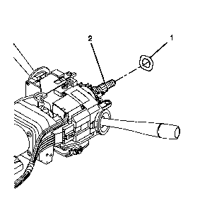
- Remove the wave washer (1) from the steering shaft (2).
- Compress the shaft lock plate (2) using J 23653-SIR andJ 42137 .
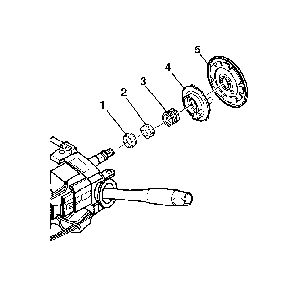
- Remove the bearing retainer (1) from the steering shaft.
- Remove J 23653-SIR andJ 42137 from the steering shaft.
- Remove the shaft lock shield (5) from the steering shaft.
- Remove the turn signal cancel cam (4) from the steering shaft.
- Remove the upper bearing spring (3) from the steering shaft .
- Remove the upper bearing inner race seat (2) from the steering shaft.
- Remove the inner race (1) from the steering shaft.
Caution: This vehicle is equipped with a Supplemental Inflatable Restraint (SIR) System. Failure to follow the correct procedure could cause the following conditions:
• Air bag deployment • Personal injury
In order to avoid the above conditions, observe the following guidelines:
• Unnecessary SIR system repairs • Refer to SIR Component Views in order to determine if you are performing service on or near the SIR components or the SIR wiring. • If you are performing service on or near the SIR components or the SIR wiring, disable the SIR system. Refer to Disabling the SIR System.


Installation Procedure
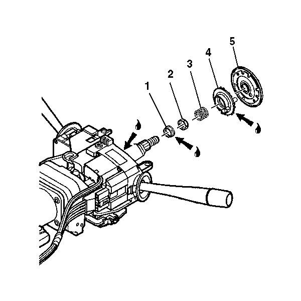
- Lubricate the inner race (1) with synthetic grease.
- Install the inner race (1) onto the steering shaft.
- Install the upper bearing inner race seat (2) onto the steering shaft.
- Install the upper bearing spring (3) onto the steering shaft.
- Lubricate the lower brass surface of the turn signal cancel cam (4) with synthetic grease.
- Install the turn signal cancel cam (4) onto the steering shaft.
- Install the shaft lock shield (5) onto the steering shaft .
- Compress the shaft lock shield (2) using J 23653-SIR and J 42137 .
- Install the new bearing retainer (1) onto the steering shaft.
- Firmly seat the bearing retainer (1) into the groove on the steering shaft.
- Remove J 23653-SIR and J 42137 from the steering shaft.
- Install the wave washer (1) onto the steering shaft (2).
- Install the SIR coil. Refer to Inflatable Restraint Steering Wheel Module Coil Replacement in SIR.
- Install the steering wheel. Refer to Steering Wheel Replacement .
- Install the inflator module. Refer to Inflatable Restraint Steering Wheel Module Replacement in SIR.
- Enable the SIR system. Refer to Enabling the SIR System in SIR.
- Connect the battery negative cable. Refer to Battery Negative Cable Disconnection and Connection in Engine Electrical.


