Information on 4T65-E MN7, M15 and M76 Front Wheel Drive Automatic Transmission Valve Body Reconditioning DTCs P0741, P0742, P0757, P0842, Harsh Shifts or Slips

| Subject: | Information On 4T65-E MN7, M15 and M76 Front Wheel Drive Automatic Transmission Valve Body Reconditioning, DTCs P0741, P0742, P0757, P842, Harsh Shifts or Slips |
| Models: | 2001-2005 Buick LeSabre, Park Avenue |
| 2002-2007 Buick Rendezvous, Rendezvous AWD |
| 2005-2007 Buick Terraza, Terraza EXT, Terraza 4WD |
| 2005-2008 Buick Allure (Canada Only), LaCrosse |
| 2006-2008 Buick Lucerne |
| 2001 Chevrolet Lumina |
| 2001-2005 Chevrolet Venture, Venture EXT, Venture 4WD |
| 2001-2007 Chevrolet Monte Carlo |
| 2001-2008 Chevrolet Impala, Lumina (Export Only) |
| 2005-2008 Chevrolet Uplander, Uplander EXT, Uplander 4WD |
| 2001-2002 Oldsmobile Intrigue |
| 2001-2003 Oldsmobile Silhouette, Silhouette EXT |
| 2004 Oldsmobile Silhouette EXT |
| 2001-2005 Pontiac Montana, Montana EXT |
| 2001-2005 Pontiac Aztek, Aztek AWD, Bonneville |
| 2001-2008 Pontiac Grand Prix |
| 2002-2005 Pontiac Montana 4WD |
| 2005-2006 Pontiac Montana SV6 (AWD) |
| 2005-2008 Pontiac Montana SV6, Montana SV6 EXT |
| 2005-2006 Saturn Relay, Relay AWD |
| 2005-2007 Saturn Relay EXT |
| with Hydra-Matic® 4T65-E (RPOs - MN7, M15, M76) Automatic Transmission |
This bulletin is being updated to include Related Service Document information. Please discard Corporate Bulletin Number 08-07-30-002 (Section 07 -- Transmission/Transaxle).
The following new service information will aid technicians in providing easy to follow valve body reconditioning instructions and new illustrations to simplify reassembly of the valve body.
Related Service Document
Corporate Bulletin Number 02-07-30-013 : Incorrect Transmission Shifts, Poor Engine Performance, Harsh 1-2 Upshifts, Slips 1st and Reverse, Torque Converter Clutch (TCC) Stuck Off/On, DTCs P0757, P0741, P0742, P0730, P0756.
Important: If valve body cleaning is not required, DO NOT disassemble bores unless it is necessary to verify movement of valves.
Inspection Procedure
- Using the exploded views in this bulletin, inspect each bore for freedom of valve(s) movement and evidence of debris. Pay particular attention to those valves related to the customer’s concern.
- Verify movement of the valves in their normal installed position. Valves may become restricted during removal or installation. This is normal due to small tolerances between the valves and bores.
- If a valve is restricted and cannot be corrected by cleaning the valve and bore, replace the valve body. Describe the restricted valve on the repair order.
Notice: Be sure all solenoids are installed with the electrical connectors facing the non-machined (cast) side of the valve body. Otherwise, the solenoids will bind against the transmission case as the valve body bolts are tightened and damage may occur.
Disassembly/Reassembly
- If a valve is restricted by a metal burr from machining that bore, remove the valve and burr, then inspect movement in the valve’s normal position. If no other debris or restrictions are found, reassemble the valve body and install in the transmission.
- If the valve body has been contaminated with debris from another transmission component failure, disassemble all bores for complete cleaning of all valve body components. If possible, keep individual bore parts separated for ease of reassembly. Use the following illustrations in this bulletin for a positive identification and location of individual parts:
- Using GM Brake Clean, or equivalent, in a safe and clean environment (clean aluminum pan) clean the valve body and dry it with compressed air.
- Clean individual valve body components with GM Brake Clean, or equivalent. Coat each valve with clean ATF and reassemble in each bore. Check each valve for free movement during assembly of each bore.
| • | Left Side Control Valve Body Assembly |
| • | Right Side Control Valve Body Assembly |
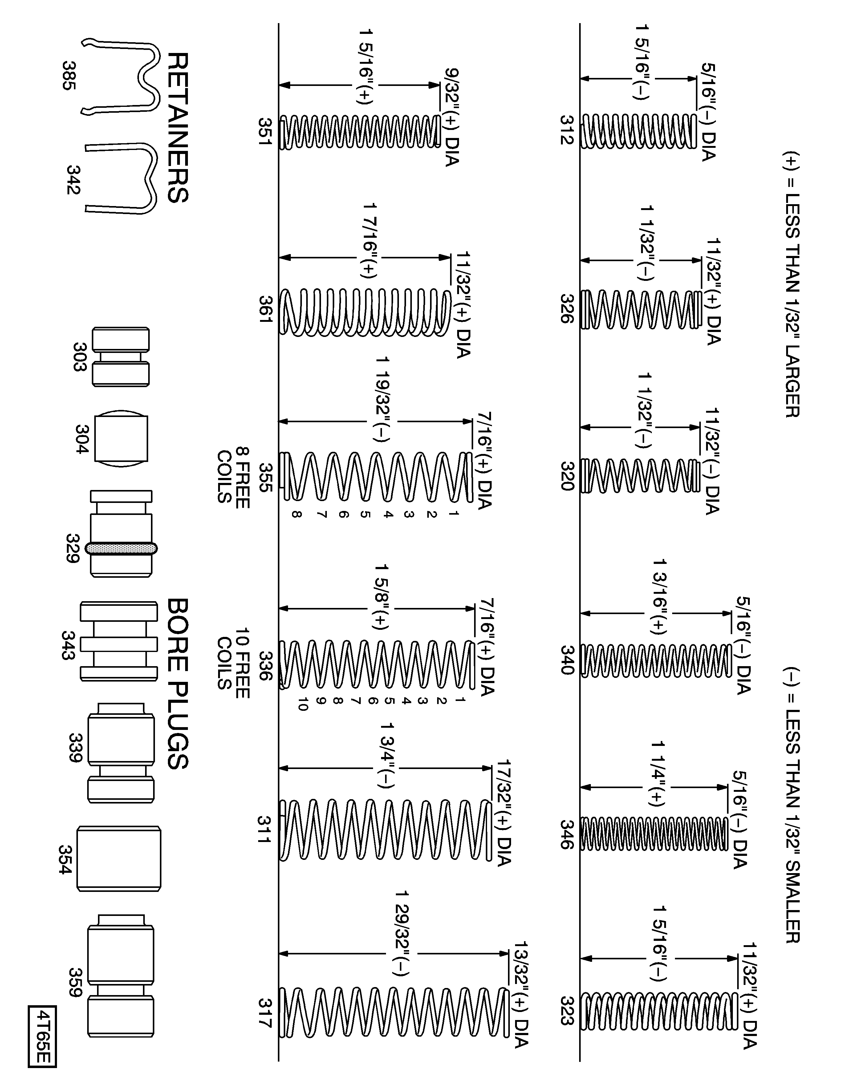
| • | Control Valve Body Assembly Chart, Valve Springs and Bore Plugs |
Caution: Use appropriate eye protection when cleaning the valve body to prevent injury.
Left Side Control Valve Body Assembly
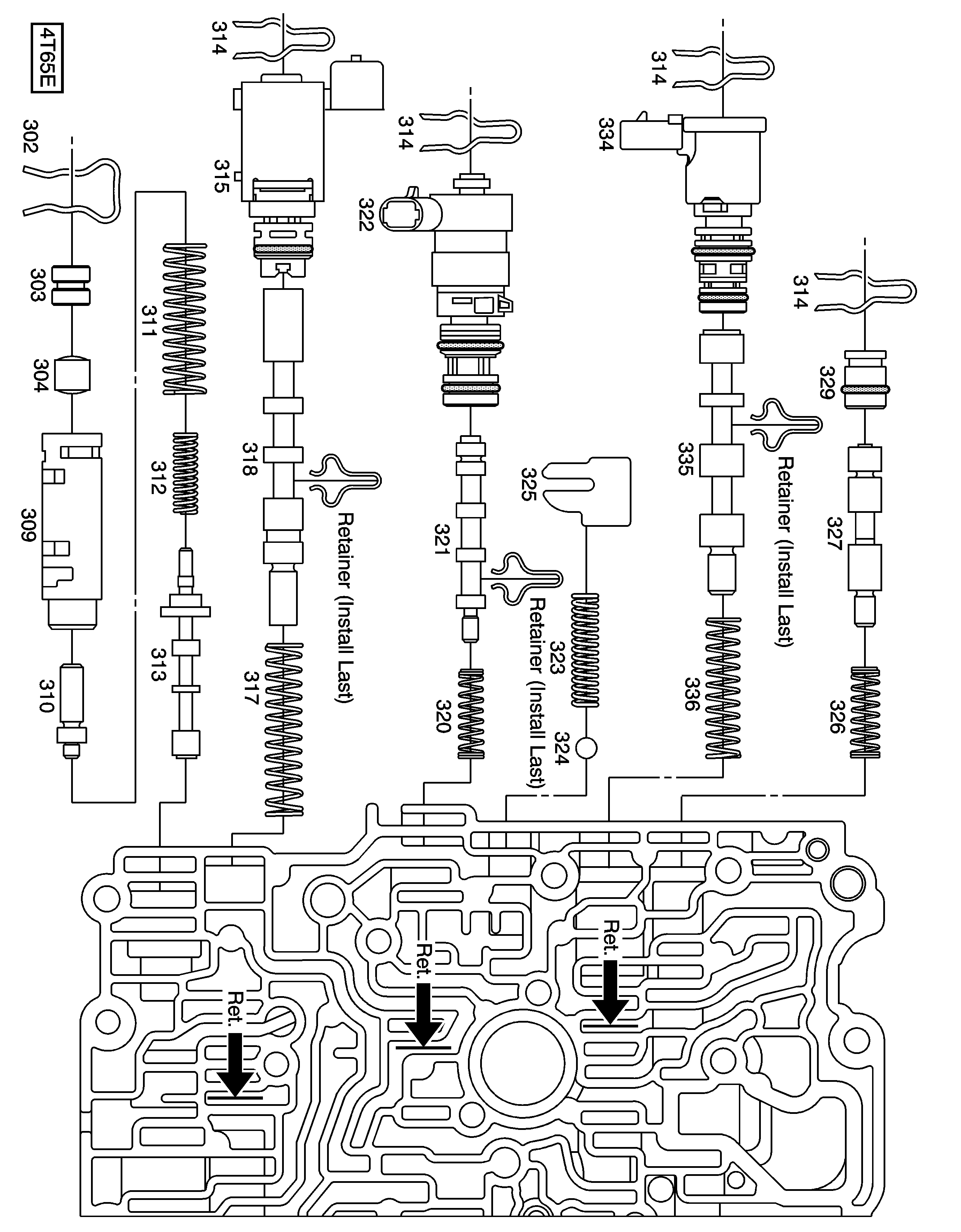
Call Out Number | Description |
|---|---|
301 | Control Valve Body (Machined) |
302 | Line Boost Valve And Bushing Retainer |
303 | Line Boost Valve Bore Plug |
304 | Line Boost Valve |
309 | Reverse Boost Valve Bushing |
310 | Reverse Boost Valve |
311 | Pressure Regulator Valve Spring Outer |
312 | Pressure Regulator Valve Inner Spring |
313 | Pressure Regulator Valve |
314 | 1-2, 3-4 Shift Solenoid Valve Retainer |
Pressure Control Solenoid Valve Retainer | |
TCC PWM Solenoid Valve Retainer | |
TCC Regulator Apply Valve Bore Plug Retainer | |
315 | 1-2, 3-4 Shift Solenoid Assembly |
317 | 1-2 Shift Valve Spring |
318 | 1-2 Shift Valve |
320 | Torque Signal Regulator Valve Spring |
321 | Torque Signal Regulator Valve |
322 | Pressure Control Solenoid Valve Assembly |
323 | Line Pressure Relief Valve Spring |
324 | Line Pressure Relief Valve |
325 | Line Pressure Relief Valve Spring Retainer |
326 | TCC Regulator Apply Valve Spring |
327 | TCC Regulator Apply Valve |
329 | TCC Regulator Apply Valve Bore Plug |
334 | TCC PWM Solenoid Valve Assembly |
335 | TCC Control Valve |
336 | TCC Control Valve Spring |
Right Side Control Valve Body Assembly
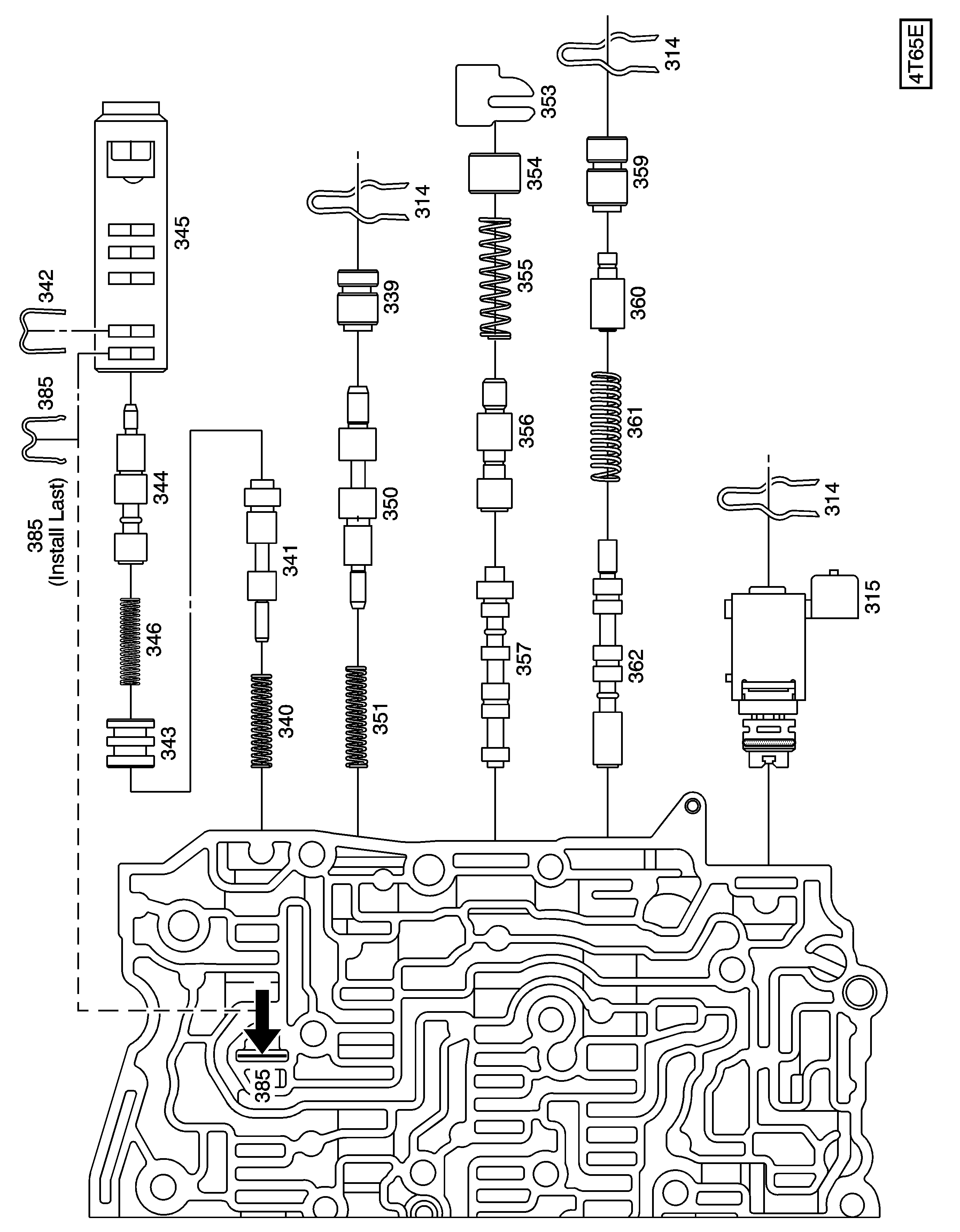
Call Out Number | Description |
|---|---|
301 | Control Valve Body (Machined) |
314 | 1-2, 3-4 Accumulator Valve Retainer |
4-3 Manual Downshift Valve Retainer | |
2-3 Shift Solenoid Valve Retainer | |
315 | 1-2, 3-4 Shift Solenoid Valve Assembly |
339 | 1-2 Accumulator Valve Bore Plug |
340 | 3-4 Accumulator Valve Spring |
341 | 3-4 Accumulator Valve |
342 | 2-3 Accumulator Valve Bushing |
343 | 2-3 Accumulator Valve Bore Plug |
344 | 2-3 Accumulator Valve |
345 | 2-3 Accumulator Valve Bushing |
346 | 2-3 Accumulator Valve Spring |
350 | 1-2 Accumulator Valve |
351 | 1-2 Accumulator Valve Spring |
353 | 3-2 Manual Downshift Valve Retainer |
354 | 3-2 Manual Downshift Valve Bore Plug |
355 | 3-2 Manual Downshift Valve Spring |
356 | 3-2 Manual Downshift Valve |
357 | 2-3 Shift Valve |
359 | 4-3 Manual Downshift Valve Bore Plug |
360 | 4-3 Manual Downshift Valve |
361 | 4-3 Manual Downshift Valve Spring |
362 | 3-4 Shift Valve |
363 | Reverse Servo Boost Valve Bore Pin |
Forward Servo Boost Valve Bore Pin | |
366 | Reverse Servo Boost Valve Spring |
Forward Servo Boost Valve Spring | |
367 | Reverse Servo Boost Valve |
Forward Servo Boost Valve | |
385 | 2-3 Accumulator Valve Retainer |
1997-2000 M.Y. Only -- Right Side Control Valve Body Assembly
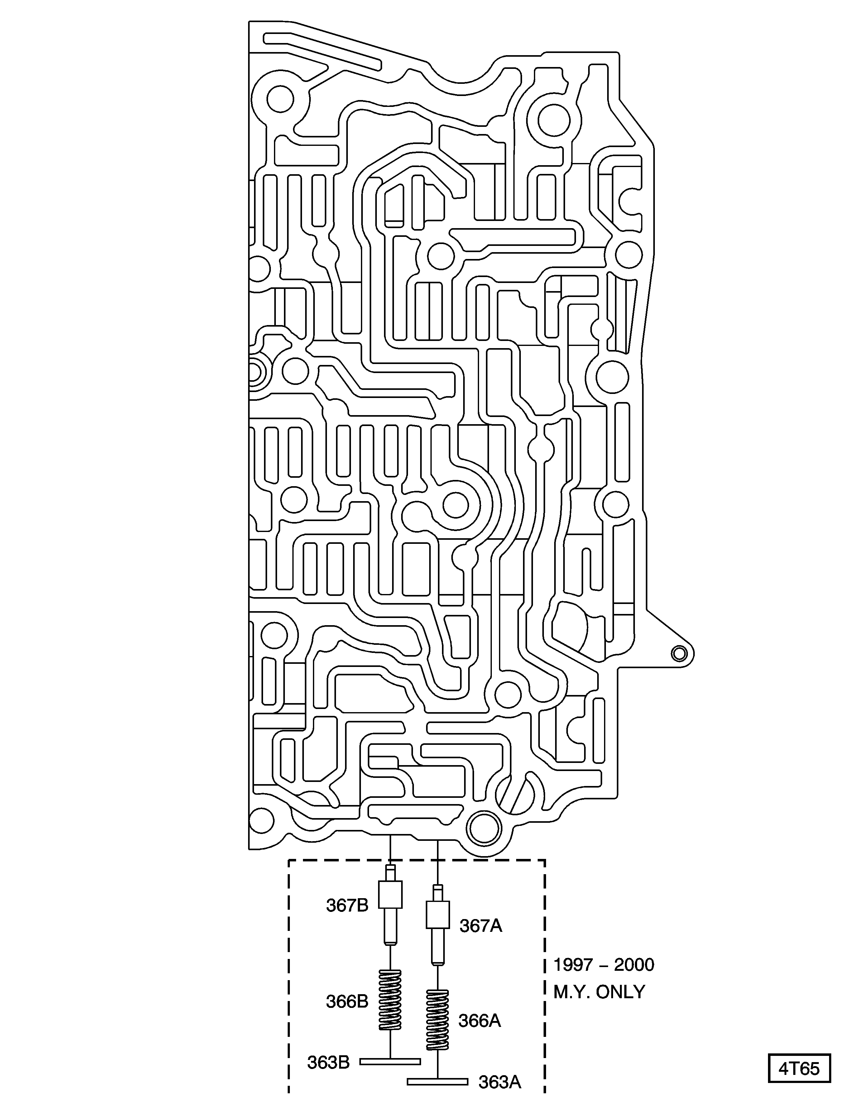
Call Out Number | Description |
|---|---|
363 | Reverse Servo Boost Valve Bore Pin |
Forward Servo Boost Valve Bore Pin | |
366 | Reverse Servo Boost Valve Spring |
Forward Servo Boost Valve Spring | |
367 | Reverse Servo Boost Valve |
Forward Servo Boost Valve |
Valve Body Spring and Bore Plug Chart (Metric)
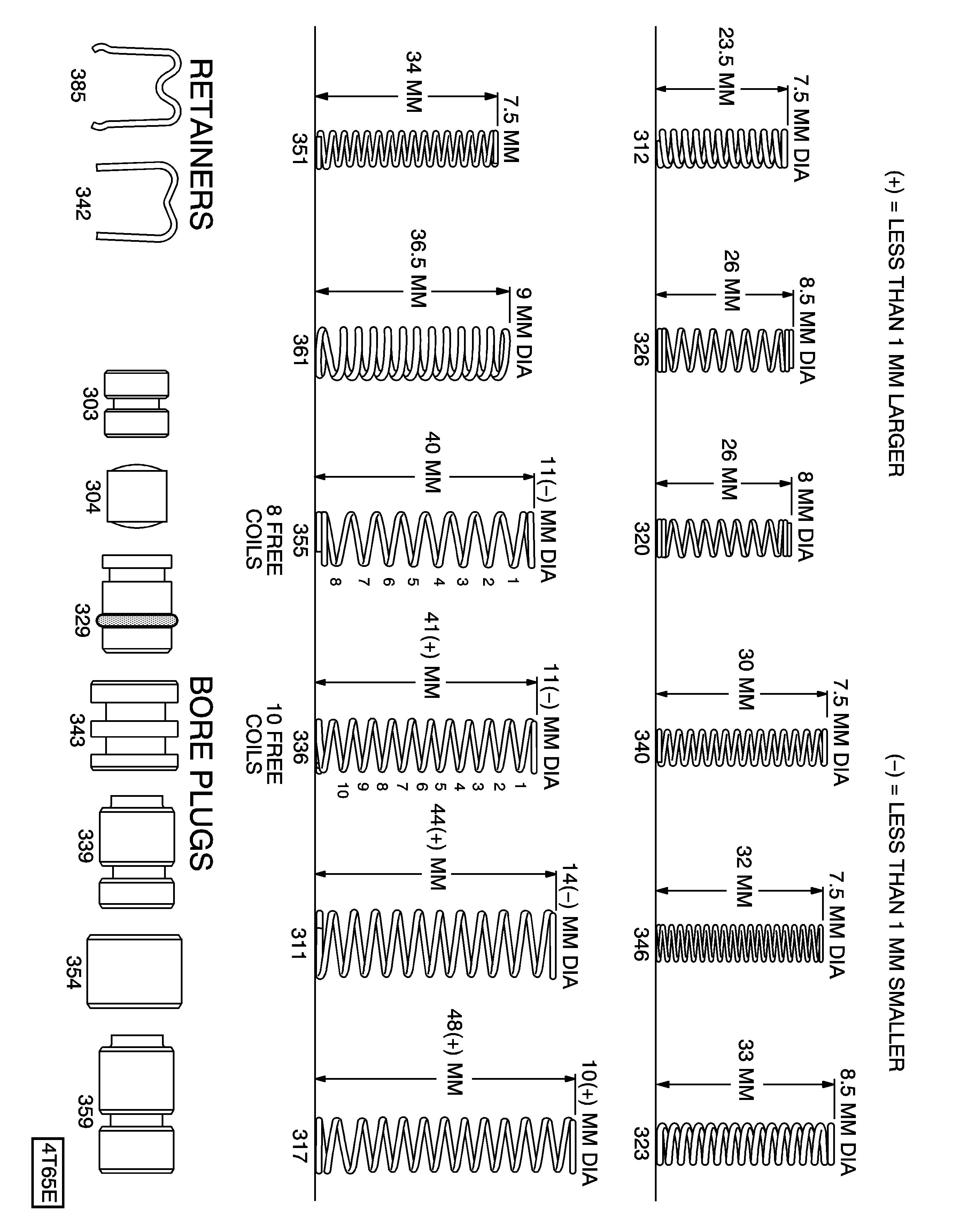
Valve Body Spring and Bore Plug Chart (Inch)
