Crankshaft Position Sensor Replacement for Chevrolet Venture Ext. 1999
Crankshaft Position Sensor Replacement 24X CKP Sensor
Removal Procedure
- Turn OFF the ignition.
- Remove the serpentine drive belt from crankshaft pulley.
- Raise the vehicle on hoist.
- Remove RH splash shield.
- Remove the crankshaft harmonic balancer retaining bolt.
- Remove the crankshaft harmonic balancer using special tool (J 24420-B).
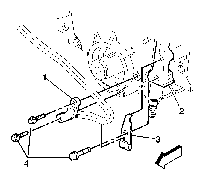
- Note the routing of sensor harness before removal.
- Remove the harness retaining clip with bolt (1).
- Remove the sensor electrical connector.
- Remove the sensor bolts (2).
- Remove the sensor.
Installation Procedure
- Install the 24X Crankshaft Position Sensor with bolts (2) and route harness as noted during removal.
- Install the harness retaining clip with bolt (1).
- Install the sensor electrical connector.
- Install the balancer on the crankshaft using special tool (J 29113).
- Apply thread sealer GM #1052080 or equivalent to threads of the crankshaft harmonic balancer bolt.
- Reinstall RH splash shield.
- Lower vehicle.
- Install the serpentine drive belt.
Notice: Use the correct fastener in the correct location. Replacement fasteners must be the correct part number for that application. Fasteners requiring replacement or fasteners requiring the use of thread locking compound or sealant are identified in the service procedure. Do not use paints, lubricants, or corrosion inhibitors on fasteners or fastener joint surfaces unless specified. These coatings affect fastener torque and joint clamping force and may damage the fastener. Use the correct tightening sequence and specifications when installing fasteners in order to avoid damage to parts and systems.
Tighten
Tighten the bolts to 10 N·m (8 lb ft).
Tighten
Tighten the bolt to 150 N·m (110 lb ft).
Crankshaft Position Sensor Replacement 7X CKP Sensor
Removal Procedure
- Turn OFF the ignition.
- Crank steering wheel fully to the left.
- Raise vehicle on hoist. Refer to Lifting and Jacking the Vehicle in general information.
- Disconnect sensor electrical connector.
- Remove shield.
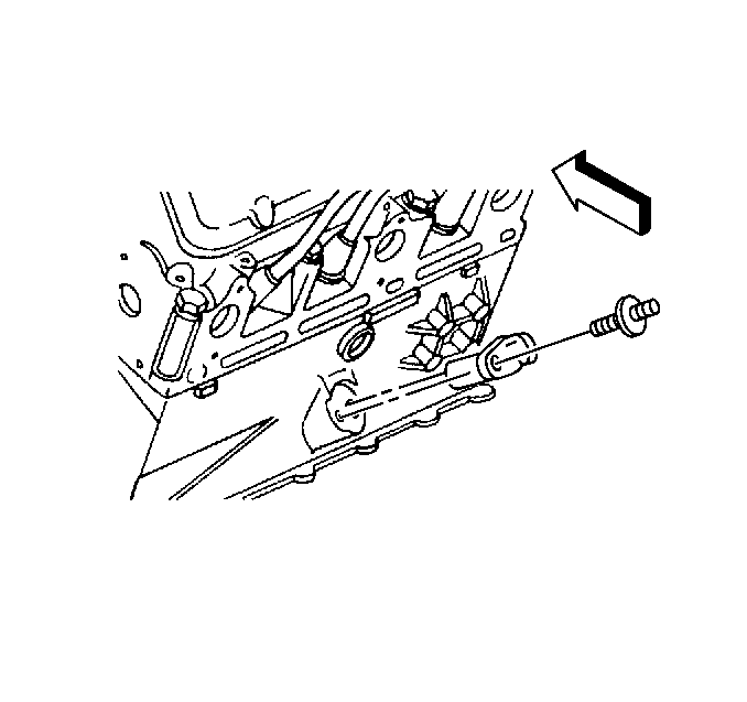
- Remove bolt/screw.
- Remove sensor from engine.
- Inspect for the following:
| 8.1. | Inspect the sensor for wear, cracks, or leakage. Replace the O-ring if necessary. |
| 8.2. | Lubricate the new O-ring with clean engine oil before installing. |
Installation Procedure
- Install the sensor to the block.
- Reinstall stall the bolt to hold sensor to block face.
- Reinstall shield.
- Connect the electrical connector.
- Lower the vehicle.
Notice: Use the correct fastener in the correct location. Replacement fasteners must be the correct part number for that application. Fasteners requiring replacement or fasteners requiring the use of thread locking compound or sealant are identified in the service procedure. Do not use paints, lubricants, or corrosion inhibitors on fasteners or fastener joint surfaces unless specified. These coatings affect fastener torque and joint clamping force and may damage the fastener. Use the correct tightening sequence and specifications when installing fasteners in order to avoid damage to parts and systems.
Tighten
Tighten the bolt to 8 N·m (71 lb in).
