Removal Procedure
- Remove the air cleaner cover and duct assembly. Refer to
Air Filter Element Replacement
in
Engine Controls.
- Recover the refrigerant. Refer to
Refrigerant Recovery and Recharging
.

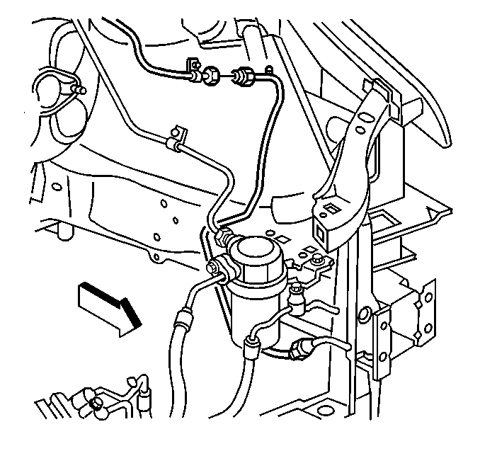
- Disconnect the liquid
line fitting at the orifice.
Important: Cap or tape the open end of the condenser line immediately to prevent
contamination.
- Using needle nose pliers, CAREFULLY grasp the edge of the expansion
(orifice) tube without touching the filter screen and pull to remove the tube;
cap or tape the evaporator tube to prevent contamination.
If you encounter difficulty during the removal of a restricted or plugged
expansion (orifice) tube, perform the following steps:
| 4.1. | Remove as much of any impacted residues as possible. |
| 4.2. | Carefully apply heat approximately ¼ inch from the
dimples on the inlet pipe. |
DO NOT overheat the pipe.
Use of the following heat devices:
| • | An equivalent to one of these heat devices |
| 4.3. | While applying heat, use needle-nosed pliers in order to grip
the orifice tube. Use a turning motion along with a push-pull motion. |
This will loosen the impacted orifice tube and remove the tube.
| 4.4. | Swab the inside of the evaporator inlet line to clean any contamination
from the line. |

- Inspect the expansion
(orifice) tube for the following conditions and clean or replace with a new
tube as indicated:
| • | Broken plastic frame; replace tube |
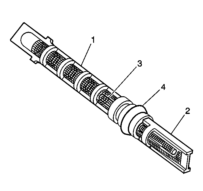
| • | Filter screen (1,2) torn, damaged or plugged with fine gritty
material; replace tube |
| • | Brass orifice tube (3) damaged or plugged; replace tube |
| • | Filter screen (1) coated with metal chips, flakes, or slivers;
coating may be removed with low pressure shop air and reused if cleaned satisfactorily |
| • | If reusing the tube, install a new O-ring (4) |
Installation Procedure

- Lightly coat the new orifice
tube O-ring seal (4) with mineral base 525 viscosity refrigerant oil.
- Remove the cap or tape from the evaporator line.
- Using needle-nose pliers, CAREFULLY grasp the edge of the expansion
(orifice) tube (long filter screen (1) inlet side of tube) without touching
the filter screen and insert the tube (short filter screen (2) outlet side
first) fully into the evaporator line.
- Remove the cap or tape from the condenser line.
- Using a lint-free clean, dry cloth, carefully clean the sealing
surfaces of the line fittings.

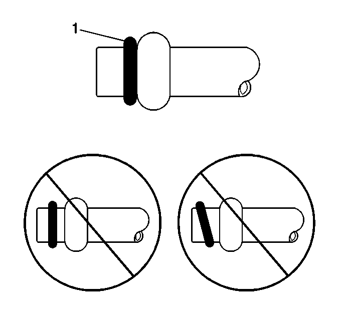
- Lightly coat the new O-ring
seal (1) with mineral base 525 viscosity refrigerant oil.
Important: DO NOT allow any of the mineral base 525 viscosity refrigerant
oil on the new O-ring seal to enter the refrigerant system.
- Carefully slide the new O-ring seal (1) onto the line fitting until
seated.
Notice: Use the correct fastener in the correct location. Replacement fasteners
must be the correct part number for that application. Fasteners requiring
replacement or fasteners requiring the use of thread locking compound or sealant
are identified in the service procedure. Do not use paints, lubricants, or
corrosion inhibitors on fasteners or fastener joint surfaces unless specified.
These coatings affect fastener torque and joint clamping force and may damage
the fastener. Use the correct tightening sequence and specifications when
installing fasteners in order to avoid damage to parts and systems.

- Install the liquid line fitting at the orifice.
Tighten
Tighten the fitting to 27 N·m (20 lb ft).
- Evacuate and charge the system. Refer to
Refrigerant Recovery and Recharging
.
- Leak test the A/C system. Refer to
Leak Testing
.
- Install the air cleaner cover and duct assembly. Refer to
Air Filter Element Replacement
in
Engine Controls.


