Testing Grid Lines
In order to locate in operative grid lines, perform the following steps:
- Start the engine.
- Turn the rear Defogger to the ON position.
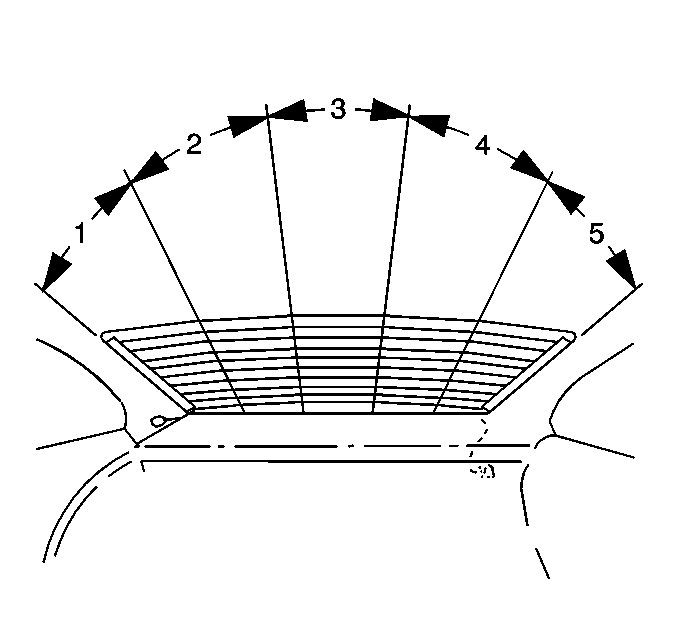
- Ground test the lamp lead and lightly touch the other probe to each grid line. Refer to the pattern of test lamp brilliance to be expected with a properly functioning grid.
- If the test lamp bulb shows full brilliance at both ends of the grid lines (zone 1 & 5), inspect for loose ground wire contact to the body metal.
- The range of zones may vary slightly from 1 window to another.
- The bulb brilliance decreases proportionately to the increased resistance in the grid line as the probe moves from the left bus bar to the right.
- Test grid lines in at least 2 places in order to eliminate the possibility of bridging a break.
- For best results, contact each grid line a few millimeters from either side of the window centerline.
- If an abnormal light reading is apparent on a specific grid line, place a test lamp probe on the grid at the left bus bar and move the probe toward the right bus bar until the light goes out.
- This indicates a break in the continuity of the grid line.

Removal Procedure
Tools Required
| • | Heat Gun - capable of 260°C (500°F) |
| • | Test lamp |
| • | Rear Window Defogger Repair Kit GM P/N 12346001 or the equivalent |
- Disconnect the electrical connector.
- Inspect the rear window grid lines.
- Ensure that the rear window is at room temperature
- Ensure that the grid line area to be repaired, is dry and free from contaminates.
- Wipe the grid line area to be repaired.
- Use a damp cloth with isopropyl alcohol in order to clean the area.
Caution: To avoid personal injury:
• Do not allow the repair material to come in contact with skin
or eyes and avoid breathing vapors. • Do not use near sparks or open flame.
Installation Procedure
Caution: When working with any type of glass or sheet metal with exposed or rough edges, wear approved safety glasses and gloves in order to reduce the chance of personal injury.
Important:
• Ensure that the grid line repair material is not beyond the expiration
date. • Use the repair decal or tape in order to control the width of
the repair area. • If you use a decal, ensure that the die-cut metering slot
is the same width as the grid line. • Thoroughly stir the grid line repair material until a uniform
color appears. • Ensure that there are no air bubbles in the grid line repair material
in the area being repaired.
- Mark the grid line break on the outside of the rear window with a grease pencil.
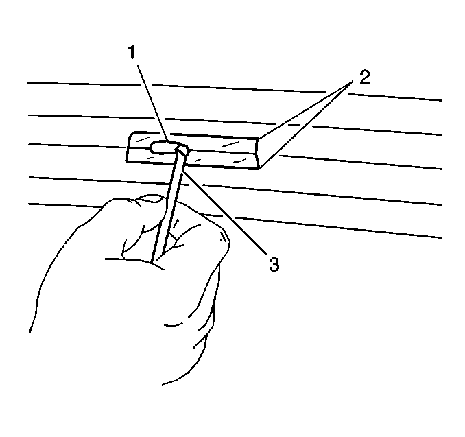
- Position the grid line repair decal or 2 strips of tape (2) above and below the repair area.
- Use the brush supplied (3) in order to spread the grid line repair material (1) until the material covers all areas of the cut-out.
- Without disturbing the grid line repair material, carefully remove the decal or tape (2).
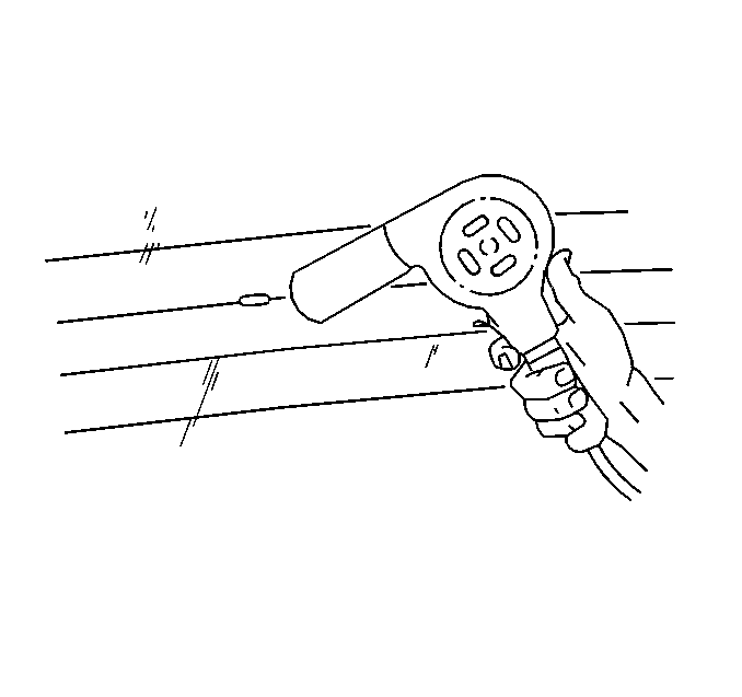
- Use a heat gun for 2-3 minutes with the nozzle 25 mm (1 in) from the surface in order to make the repair.
- Connect the electrical connector.
- Test the grid line operation in order to verify the grid line repair.

Notice: The grid line repair material must be cured with heat. To avoid heat damage to the interior trim, protect the trim near the repair area where heat is to be applied.

Important:
• In order to completely cure the repair materials, heat at least
24 hours at an ambient temperature of 21-32°C (70-90°F) • Do NOT disturb the repair area until after the repair materials
are fully cured. • The grid line operates immediately after the repair.
