Important: Lubricate all moving parts of the linear shift assembly with synthetic
grease.
- Proceed with the following steps if re-assembling the linear shift assembly.
If the linear shift assembly is already assembled, proceed with step 10.
Notice: Use the correct fastener in the correct location. Replacement fasteners
must be the correct part number for that application. Fasteners requiring
replacement or fasteners requiring the use of thread locking compound or sealant
are identified in the service procedure. Do not use paints, lubricants, or
corrosion inhibitors on fasteners or fastener joint surfaces unless specified.
These coatings affect fastener torque and joint clamping force and may damage
the fastener. Use the correct tightening sequence and specifications when
installing fasteners in order to avoid damage to parts and systems.
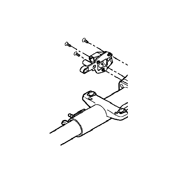
- Install the gearshift
lever assembly support bracket and secure by using 3 flat head 6-lobed
socket tap screws.
Tighten
Tighten the screws to 10 N·m (89 lb in).
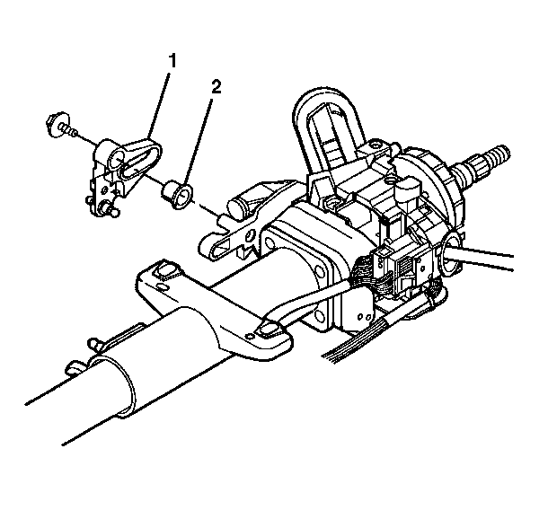
- Insert the cam bushing (2)
into the cable shift cam assembly (1).
- Install the cable shift cam assembly (1).
- Install the hexagon flange head bolt.
Tighten
Tighten the screw to 18 N·m (14 lb ft).
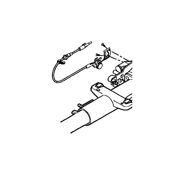
- Install the park lock
cable assembly and secure by using the 2 oval head 6-lobed socket tap
screws.
Tighten
Tighten the screws to 6.5 N·m (58 lb in).
- Install the shift lever
clevis (1).
- Install the ball actuator assembly (2).
- Install the hexagon flanged head bolt.
Tighten
Tighten the bolt to 18 N·m (14 lb ft).
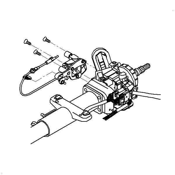
- Install the linear shift
assembly and secure by using 3 flat head 6-lobed socket tap screws.
The linear shift assembly must be out of the PARK position to install
the lower socket tap screw.
Tighten
Tighten the screws to 10 N·m (89 lb in).
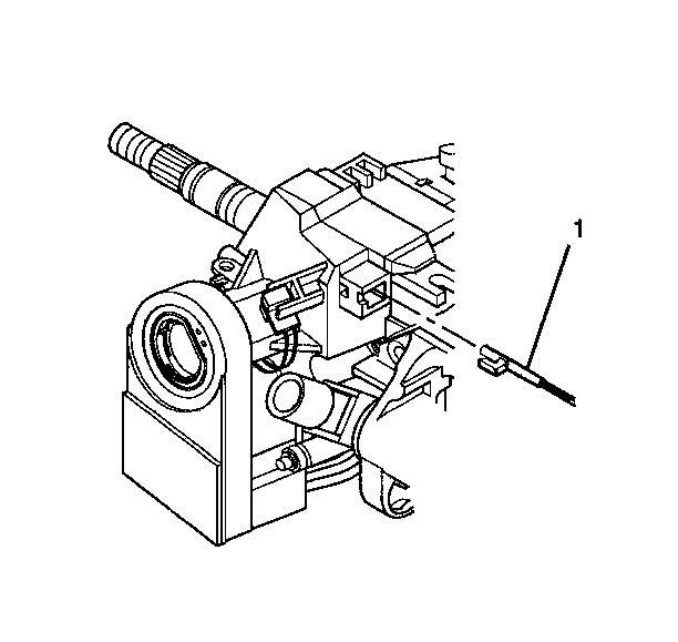
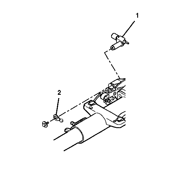
- Connect the park lock
cable assembly (1) into the electronic lock module assembly.
| • | The lock cylinder should be in the OFF-LOCK position. |
| • | The locking tab at the end of the park lock cable assembly (1)
must be installed into the electronic lock module assembly. |
- Install the automatic
transmission shift lock control.
Install the gear shift lever and put the column in the NEUTRAL position.
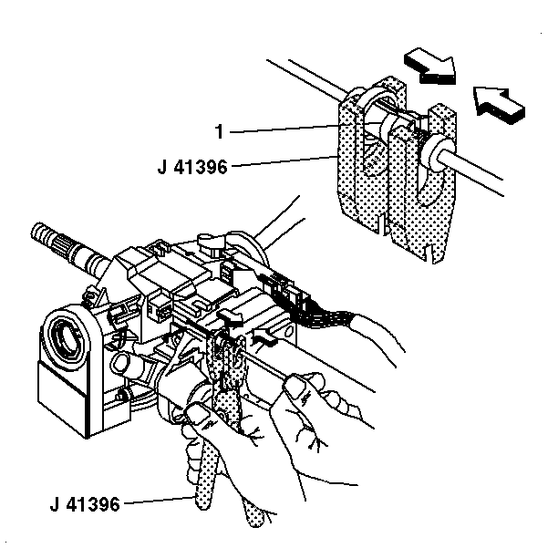
- Adjust the park lock cable
assembly.
| 13.1. | Use the gear shift lever to put the column in the PARK position. |
| 13.2. | Put the ignition switch in the OFF-LOCK position. Remove the key. |
| 13.3. | Unlock the adjuster ring (1) on the park lock cable assembly
with J 41396
. |
| 13.4. | Pull on the cable until the park lock latch contacts the gear
shift lever. Release the cable. |
| 13.5. | Lock the adjuster ring (1) securely in place on the park
lock cable assembly with J 41396
. |
- Inspect the park lock cable assembly.
| 14.1. | Put the lock cylinder in the OFF-LOCK position. The gear shift
lever should not be able to shift out of the PARK position. |
| 14.2. | Turn the key to the RUN position and put the gear shift lever
in the NEUTRAL position. |
| 14.3. | With the gear shift lever in the NEUTRAL position the lock cylinder
should not be able to go into the OFF-LOCK position. |
| 14.4. | Put the gear shift lever in the PARK position. |
| 14.5. | Put the lock cylinder in the OFF-LOCK position and then remove
the key. |
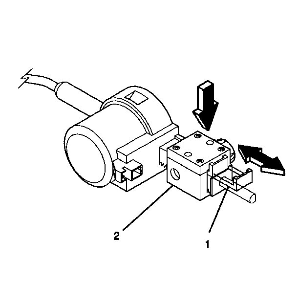
- Adjust the automatic transmission
shift lock control.
| 15.1. | Pull the tab (1) out on the block side (2) of the
automatic transmission shift lock control. |
| 15.2. | Press on the adjuster block (2) to compress the internal
adjuster spring to disengage the adjuster teeth. Slide the adjuster block
as far away from the solenoid as possible. |
| 15.3. | Lock in place by pushing the tab (1) back in. |
- Inspect the automatic transmission shift lock control.
| 16.1. | The automatic transmission shift lock control must lock the gear
shift lever when it is put into the PARK position. |
| 16.2. | When the column is installed in the vehicle you will not be able
to shift the gear shift lever out of the PARK position without pressing on
the brake pedal. The solenoid will be energized. |
| 16.3. | Readjust if needed. |
- Install the shift lever assembly. Refer to
Shift Lever Replacement - On Vehicle
.
- Install the upper and lower trim covers. Refer to
Steering Column Trim Covers - Assemble - Off Vehicle
.
- Enable the inflatable restraint steering wheel module. Refer to
Enabling the SIR System
in SIR.
