Removal Procedure
- Disconnect the battery negative cable. Refer to Battery Negative Cable Disconnection and Connection in Engine Electrical.
- Remove the right closeout/insulator panel. Refer to Instrument Panel Insulator Panel Replacement - Right Side .
- Remove the left closeout/insulator panel. Refer to Instrument Panel Insulator Panel Replacement - Left Side .
- Remove the knee bolster. Refer to Knee Bolster Replacement .
- Remove the instrument panel (I/P) accessory trim plate. Refer to Instrument Panel Accessory Trim Plate Replacement .
- Remove the I/P compartment. Refer to Instrument Panel Compartment Replacement .
- Disable the SIR system. Refer to SIR Disabling and Enabling in SIR.
- Remove the inflatable restraint I/P module. Refer to Inflatable Restraint Instrument Panel Module Replacement in SIR.
- Remove the underhood electrical center. Refer to Underhood Electrical Center or Junction Block Replacement in Wiring Systems.
- Remove the Instrument Panel Cluster (IPC). Refer to Instrument Cluster Replacement .
- Remove the steering column. Refer to Steering Column Replacement in Steering Wheel and Column.
- Remove the hood release handle. Refer to Hood Primary Latch Release Cable Handle Replacement in Body Front End.
- Remove the front floor console. Refer to Front Floor Console Replacement .
- Remove the front floor console bracket. Refer to Floor Console Bracket Replacement .
- Remove the audio system. Refer to Radio Replacement in Entertainment.
- Remove the heater A/C controls. Refer to HVAC Control Module Replacement in HVAC Systems - Manual.
- Remove the switch bank. Refer to Instrument Panel Multifunction Switch Assembly Replacement in Lighting Systems.
- Remove the windshield pillar garnish molding. Refer to Windshield Pillar Garnish Molding Replacement in Interior Trim.
- Remove the I/P upper trim. Refer to Instrument Panel Upper Trim Pad Replacement .
- Remove the headlamp switch. Refer to Headlamp Switch Replacement in Lighting Systems.
- Remove the data link connector. Refer to Data Link Connector Replacement in Data Link Communication.
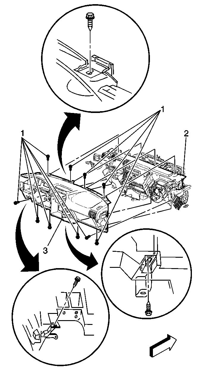
- Remove the bolts/screws (1) that secure the instrument panel (3) to the body.
- Lift up from the bottom of the I/P in order to release the top retainers.
- Remove the I/P wiring harness. Refer to Instrument Panel Wiring Harness Replacement .
- Remove the instrument panel (3).

Installation Procedure
- Perform the following steps in order to install the instrument panel (2) to the body:
- Install the I/P wiring harness. Refer to Instrument Panel Wiring Harness Replacement .
- Install the bolts/screws (1) to the I/P body (3).
- Install the data link connector. Refer to Data Link Connector Replacement in Data Link Communication.
- Install the headlamp switch. Refer Headlamp Switch Replacement in Lighting Systems.
- Install the I/P upper trim. Refer to Instrument Panel Upper Trim Pad Replacement .
- Install the windshield pillar garnish molding. Refer to Windshield Pillar Garnish Molding Replacement in Interior Trim.
- Install the switch bank. Refer to Instrument Panel Multifunction Switch Assembly Replacement in Lighting Systems.
- Install the heater A/C controls. Refer to HVAC Control Module Replacement in HVAC Systems - Manual.
- Install the audio system. Refer to Radio Replacement in Entertainment.
- Install the front floor console bracket. Refer to Floor Console Bracket Replacement .
- Install the front floor console. Refer to Front Floor Console Replacement .
- Install the hood release handle. Refer to Hood Primary Latch Release Cable Handle Replacement in Body Front End.
- Install the steering column. Refer to Steering Column Replacement in Steering Wheel and Column.
- Install the IPC. Refer to Instrument Cluster Replacement .
- Install the underhood electrical center. Refer to Underhood Electrical Center or Junction Block Replacement in Wiring Systems.
- Install the inflatable restraint I/P module. Refer to Inflatable Restraint Instrument Panel Module Replacement in SIR.
- Install the I/P compartment. Refer to Instrument Panel Compartment Replacement .
- Install the I/P accessory trim plate. Refer to Instrument Panel Accessory Trim Plate Replacement .
- Install the knee bolster. Refer to Knee Bolster Replacement .
- Install the left closeout/insulator panel. Refer to Instrument Panel Insulator Panel Replacement - Left Side .
- Install the right closeout/insulator panel. Refer to Instrument Panel Insulator Panel Replacement - Right Side .
- Connect the negative battery cable. Refer to Battery Negative Cable Disconnection and Connection in Engine Electrical.
- Enable the SIR system. Refer to SIR Disabling and Enabling in SIR.

Important: The instrument panel (I/P) will rest off of the lower mounts when you lower the I/P. This will aid in the routing of the wiring harness. Prop the I/P up in order to route the harness, as needed.
| 1.1. | Secure the top retainers. |
| 1.2. | Lower the instrument panel (I/P). |
Notice: Use the correct fastener in the correct location. Replacement fasteners must be the correct part number for that application. Fasteners requiring replacement or fasteners requiring the use of thread locking compound or sealant are identified in the service procedure. Do not use paints, lubricants, or corrosion inhibitors on fasteners or fastener joint surfaces unless specified. These coatings affect fastener torque and joint clamping force and may damage the fastener. Use the correct tightening sequence and specifications when installing fasteners in order to avoid damage to parts and systems.
Tighten
Tighten the bolts/screws to 10 N·m (89 lb in).
