For 1990-2009 cars only
Special Tools
J 36660-A Torque Angle Meter
Removal Procedure
- Remove the valve rocker arm cover(s). Refer to Valve Rocker Arm Cover Replacement - Left Side and/or Valve Rocker Arm Cover Replacement - Right Side.
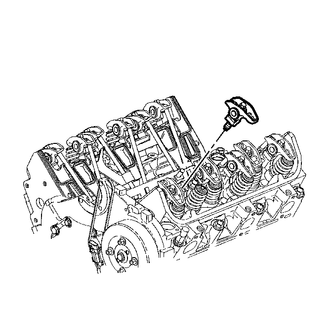
- Remove the rocker arm bolt(s).
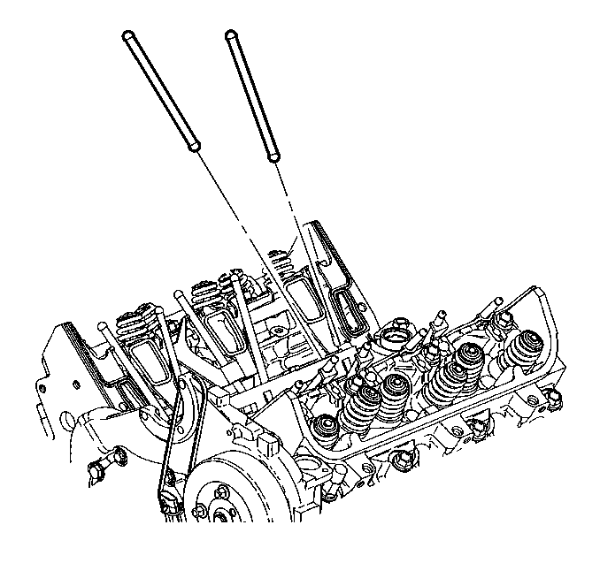
- Remove the valve rocker arm(s) and the pushrod(s).

Important: Keep the components separated in order to install the components in the same location.
Important: Retain the pushrods in the order that they are removed. Keeping the components in order will ensure installation into the original position.
Installation Procedure
- Coat the ends of the push rods and rocker arm friction surfaces using prelube GM P/N 12345501 or GM P/N 88862586 (Canadian P/N 992704 or Canadian P/N 88862586) or the equivalent.
- Install the push rods in their original location.
- Install the valve rocker arm(s) and the bolt(s).
- Install the valve rocker arm cover(s). Refer to Valve Rocker Arm Cover Replacement - Left Side and/or Valve Rocker Arm Cover Replacement - Right Side.

Important: The intake valve push rods measure 144 mm (5.75 in) in length, (yellow). The exhaust valve push rods measure 152.5 mm (6.0 in) in length, (green).
Notice: Refer to Fastener Notice in the Preface section.

Tighten
Use the
J 36660-A
to tighten the bolts to 19 N·m (14 lb ft) plus an additional 30 degrees.
