ASI Resolution - Power Sliding Side Door Inoperative (Code 22) (Replace Optical Sensor)

| Subject: | Power Sliding Side Door Inoperative (Code 22) (Replace Optical Sensor) |
| Models: | 2002-2005 Chevrolet Venture |
| 2002-2004 Oldsmobile Silhouette |
| 2002-2005 Pontiac Montana |
This bulletin is being revised to provide the Correction and Parts information for Advanced Service Information Bulletin Number 04-08-64-015. Please discard Corporate Bulletin Number 04-08-64-015 (Section 08 - Body and Accessories)
Condition
Some customers may comment that the power sliding side door is inoperative.
Cause
The power sliding side door optical sensor may have failed.
Correction
Follow SI Document ID 690381 listed below for diagnosis.
DTC 022
Circuit Description
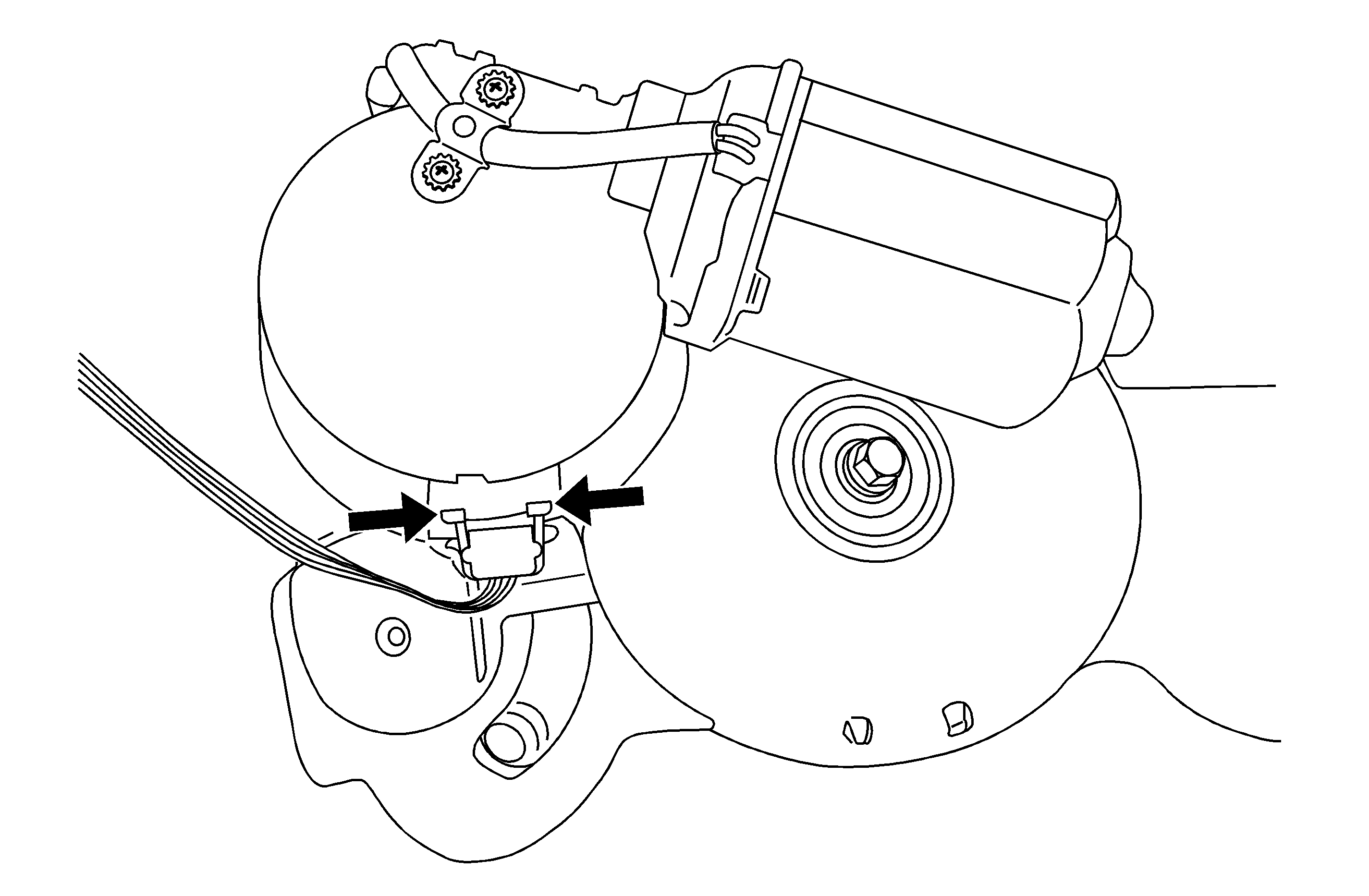
The rear side door actuator control module uses an optical sensor to monitor the sliding door position at all times. The optical sensor requires a 5-volt reference and reference return from the rear side door actuator control module. There are 2 signal circuits from the optical sensor to the rear side door actuator control module. The optical sensor sends pulses through both signal circuits to the power sliding door (PSD) module whenever the sliding door is in motion. The optical sensor pulses allow the rear side door actuator control module to calculate the position of the sliding door at all times. The optical sensor signal circuits switch from 0.01-4.5 volts as the sliding door is moving.
Conditions for Running the DTC
A DTC 022 may be set whenever the sliding door is in motion.
Conditions for Setting the DTC
The rear side door actuator control module does not detect the optical sensor pulses while the sliding door opening or closing.
Action Taken When the DTC Sets
| • | The rear side door actuator control module will attempt to operate the door and stop if the condition is current. |
| • | The rear side door actuator control module sets DTC 022. |
Conditions for Clearing the DTC
All stored DTCs are cleared whenever the on-board diagnostic modes are exited.
Diagnostic Aids
| • | Inspect the optical sensor connector and terminals for damage. |
| • | Inspect the optical sensor pigtail harness for damage. |
| • | Inspect the optical sensor for proper installation and a secure mount to the actuator motor housing. |
Test Description
The numbers below refer to the step numbers on the diagnostic table.
3. Tests the rear side door actuator control module for the optical sensor 5-volt reference and ground.
4. Tests the optical sensor signal circuit. While the door is moving at the approximate power operating speed, the average voltage measured should be 2-3 volts.

Refer to the illustration above for sensor location.
Step | Action | Values | Yes | No |
|---|---|---|---|---|
Schematic Reference: Power Sliding Door (PSD) Schematics Connector End View Reference: Power Door Systems Connector End Views | ||||
1 | Did you perform the Power Door Systems Diagnostic System Check ? | -- | Go to Step 2 | Go to Diagnostic System Check - Door Systems |
2 |
Is there continuity between any of the circuits? | -- | Go to Step 8 | Go to Step 3 |
3 |
Is the voltage the specified value? | 5V | Go to Step 4 | Go to Step 10 |
4 |
Is the voltage the within specified values? | 0.01-4.5 V | Go to Step 5 | Go to Step 8 |
5 |
Is the voltage the within specified values? | 0.01-4.5 V | Go to Step 6 | Go to Step 8 |
6 |
Is the resistance within the specified values? | 1-3 ohms | Go to Step 7 | Go to Step 9 |
7 |
Is the resistance within the specified values? | 2-5 ohms | Go to Step 10 | Go to Step 9 |
8 | Inspect and if possible, repair any damage to the optical sensor pigtail harness or connector. Refer to Wiring Repairs and Connector Repairs in Wiring Systems. Did you find and correct the condition? | -- | Go to Step 14 | Go to Step 11 |
9 | Inspect and if possible, repair any damage to the pigtail harness or connector. Refer to Wiring Repairs and Connector Repairs in Wiring Systems. Did you find and correct the condition? | -- | Go to Step 14 | Go to Step 12 |
10 | Inspect for poor connections at the rear side door actuator control module. Refer to Testing for Intermittent Conditions and Poor Connections and Connector Repairs in Wiring Systems. Did you find and correct the condition? | -- | Go to Step 14 | Go to Step 13 |
11 | Replace the optical sensor. Refer to Rear Side Door Actuator Sensor Replacement. Is the repair complete? | -- | Go to Step 14 | -- |
12 | Replace the actuator motor and clutch assembly. Refer to Motor Clutch Replacement - Power Sliding Door . Is the repair complete? | -- | Go to Step 14 | -- |
13 | Replace the rear side door actuator control module. Refer to Actuator Control Module Replacement - PSD . Is the repair complete? | -- | Go to Step 14 | -- |
14 | Re-initialize the PSD and operate the system in order to verify the repair. Did you correct the condition? | -- | System OK | Go to Step 2 |
Parts Information
Part Number | Description |
|---|---|
16619860 | Sensor Asm - RR S/D Sliding |
Parts are currently available from GMSPO.
Warranty Information
For vehicles repaired under warranty, use:
Labor Operation | Description | Labor Time |
|---|---|---|
N9506 | Optical Sensor, Right - Replace | 0.7 hr |
N9507 | Optical Sensor, Left - Replace | 0.8 hr |
