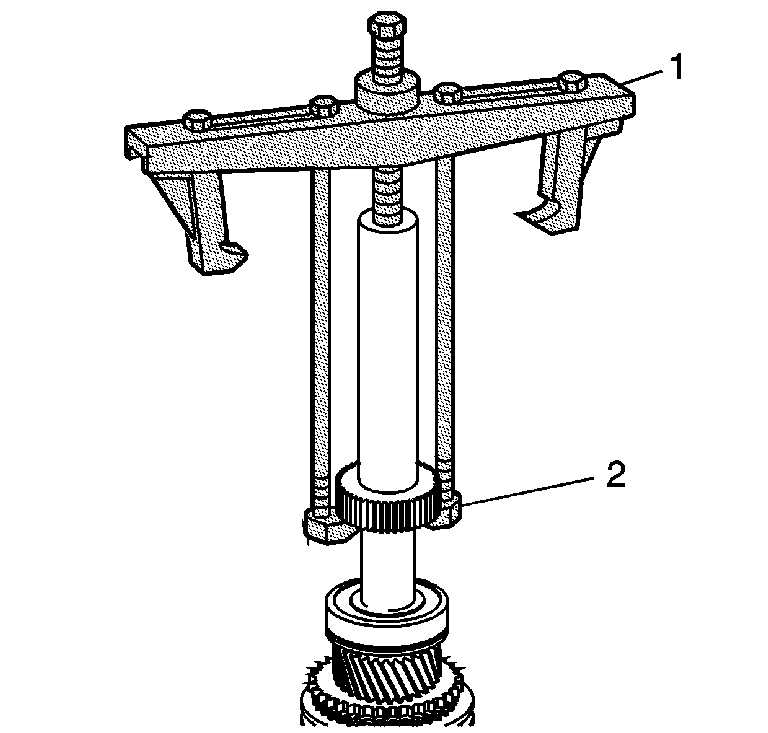
- Use the J 21427-A
(2) and the J 8433
(1) in order to remove the speed sensor
reluctor wheel from the mainshaft. It will be necessary to use 2 25 mm
(12 in) long bolts with 3/8 in NC threads.
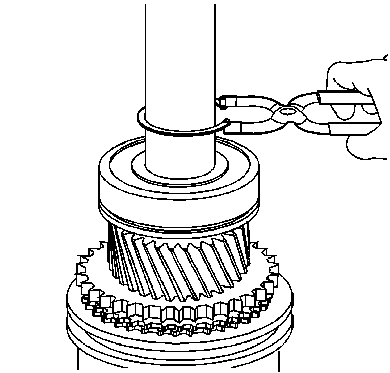
- Remove the mainshaft rear bearing retaining
ring.
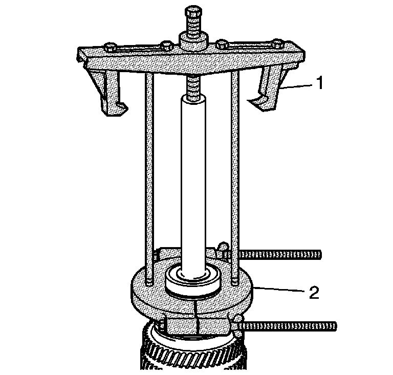
- Use the J 8433
(1)
and the J 36513
(2) in
order to remove the mainshaft rear bearing. Use 2 25 mm (12 in)
long bolts with 3/8 in NC thread.
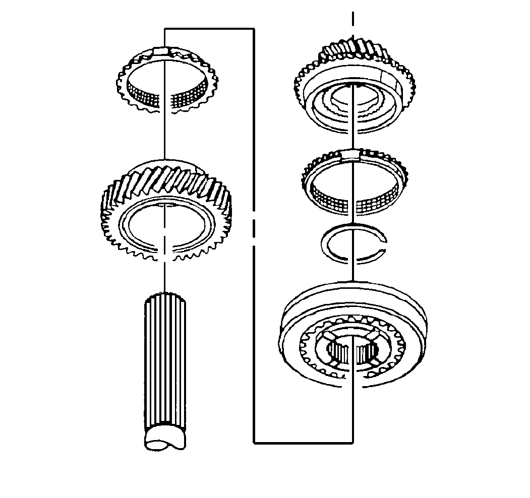
Important:
| • | Keep the synchronizer blocking rings against the synchronizer
sleeve when removing the 5th/reverse synchronizer from the mainshaft . Removing
the synchronizer blocking rings will allow the springs, detent balls and
inserts to pop out from the synchronizer hub. |
| • | The reverse and fifth gear blocking rings look the same, but are
not interchangeable. Prior to removing the reverse gear blocking ring from
the main shaft, mark the reverse gear blocking ring for installation identification. |
- Remove the 5th speed gear from the output end of the main shaft.
- Remove the retaining ring for the 5th/reverse synchronizer hub.
- Remove the 5th/reverse synchronizer assembly with the blocking
rings.
- Remove the reverse speed gear
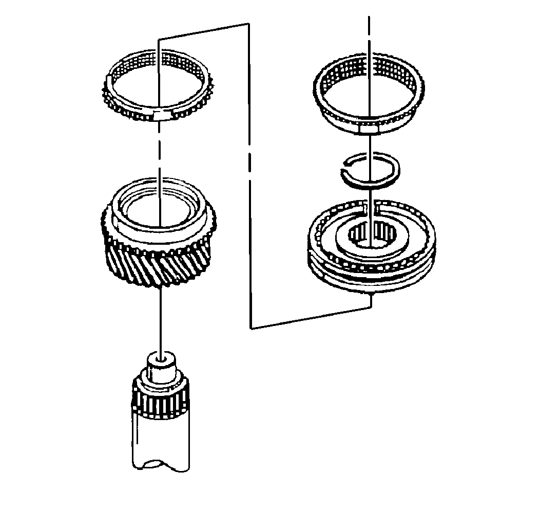
- Remove the retaining ring
for the 3rd/4th synchronizer assembly from the front of the main shaft.
Important: Keep the synchronizer blocking rings against the synchronizer sleeve
when removing the 3rd/4th synchronizer assembly from the mainshaft. Removing
the synchronizer blocking rings will allow the springs, detent balls and
inserts to pop out from the synchronizer hub.
- If required, use a hydraulic press supporting under the 3rd gear and
remove the following components from the mainshaft. The 3rd/4th synchronizer
may not require a press for removal.
| • | The 4th gear synchronizer blocking ring |
| • | The 3rd/4th gear synchronizer |
| • | The 3rd gear synchronizer blocking ring |
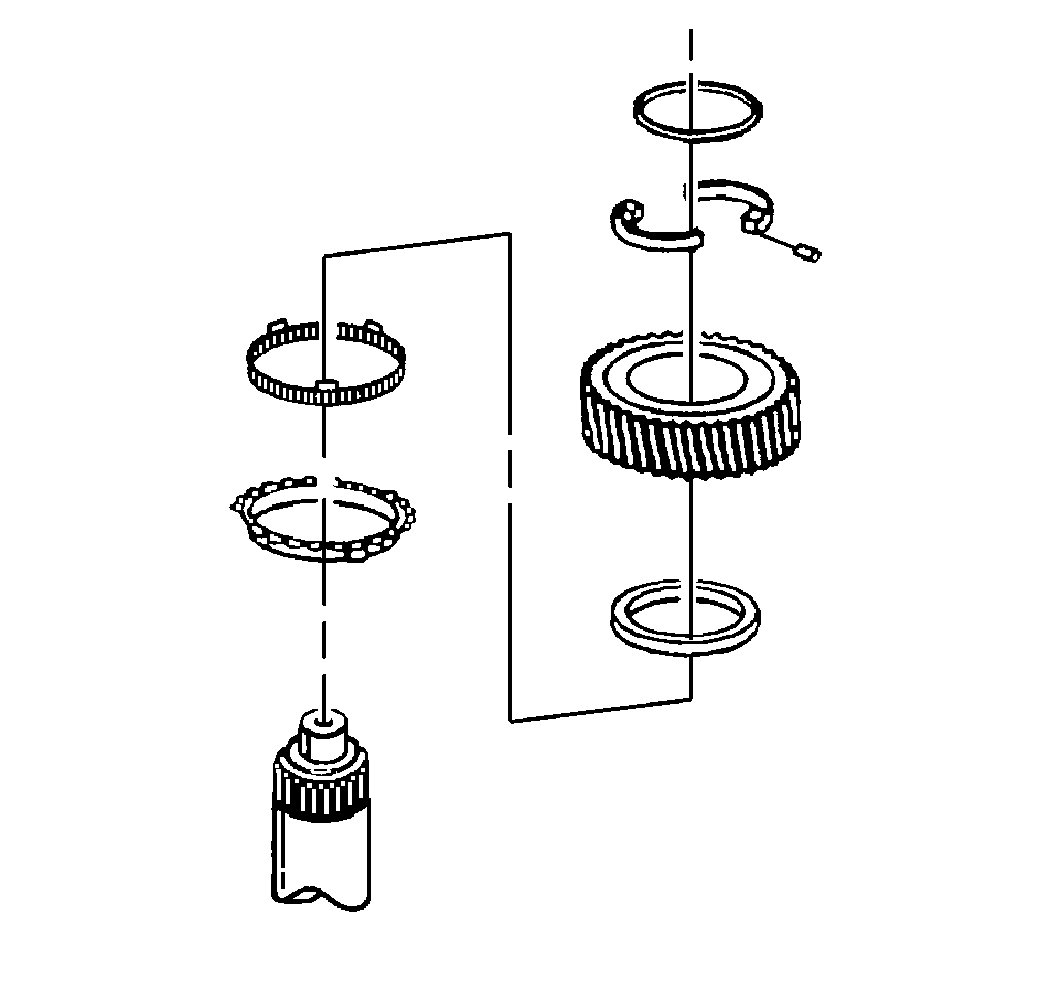
- Remove the following components
from the main shaft. Do not remove the 2nd gear synchronizer blocking ring
at this time.
| • | The 2nd/3rd gear thrust washer retaining ring |
| • | The thrust washer and lock pin |
| • | The 2nd gear inner synchronizer ring |
| • | The 2nd gear middle synchronizer ring |
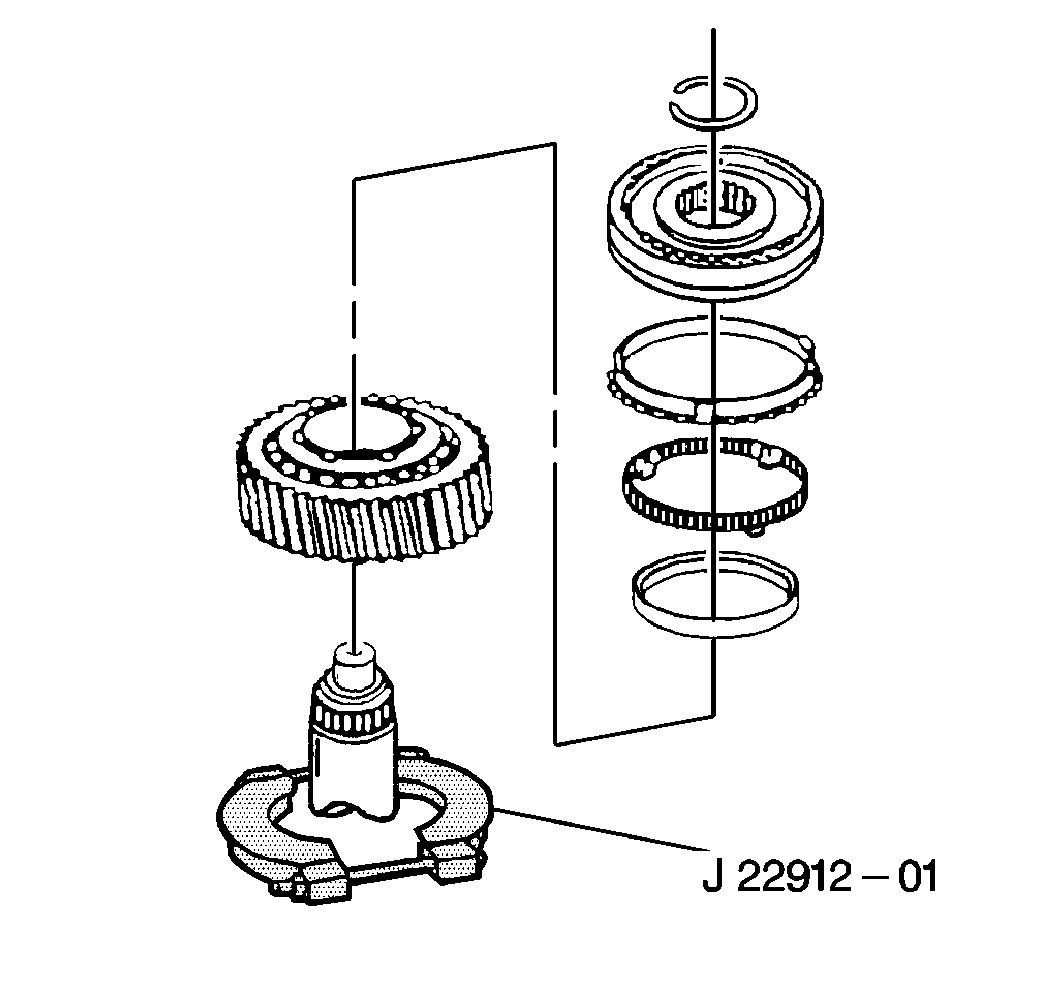
- Remove the retaining ring
for the 1st/2nd gear synchronizer from the mainshaft.
Important:
| • | Keep the synchronizer blocking rings against the synchronizer
sleeve when removing the 1st/2nd synchronizer assembly from the mainshaft.
Removing the synchronizer blocking rings will allow the springs, detent
balls and ball retainers to pop out from the synchronizer hub. |
| • | Scribe the 1st/2nd synchronizer hub for alignment with the main
shaft prior to disassembly. |
- If required, use a hydraulic press and the J 22912-01
under the 1st speed gear and remove the following components
from the main shaft. The 1st/2nd synchronizer may not require using a press
for removal.
| • | The 2nd gear synchronizer blocking ring |
| • | The 1st/2nd gear synchronizer assembly |
| • | The 1st gear synchronizer blocking ring |
| • | The 1st gear middle synchronizer ring |
| • | The 1st gear inner synchronizer ring |


