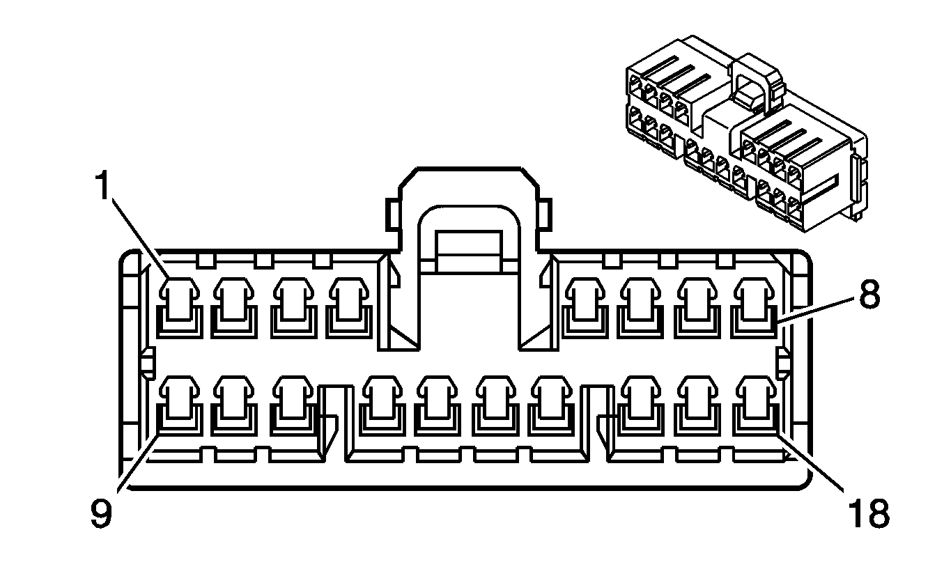
| Table 1: | Radio |
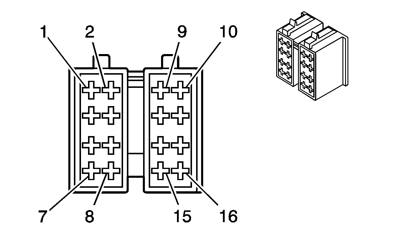
| Table 2: | RDS Radio C1 |
| Table 3: | RDS Radio C2 |
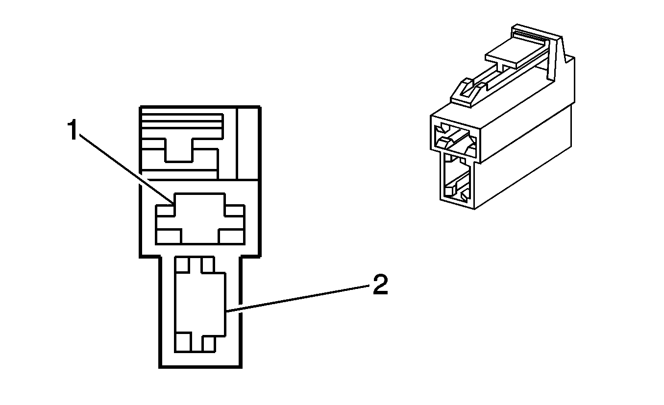
| Table 4: | Speaker - Driver Front |
| Table 5: | Speaker - Left Front Tweeter |
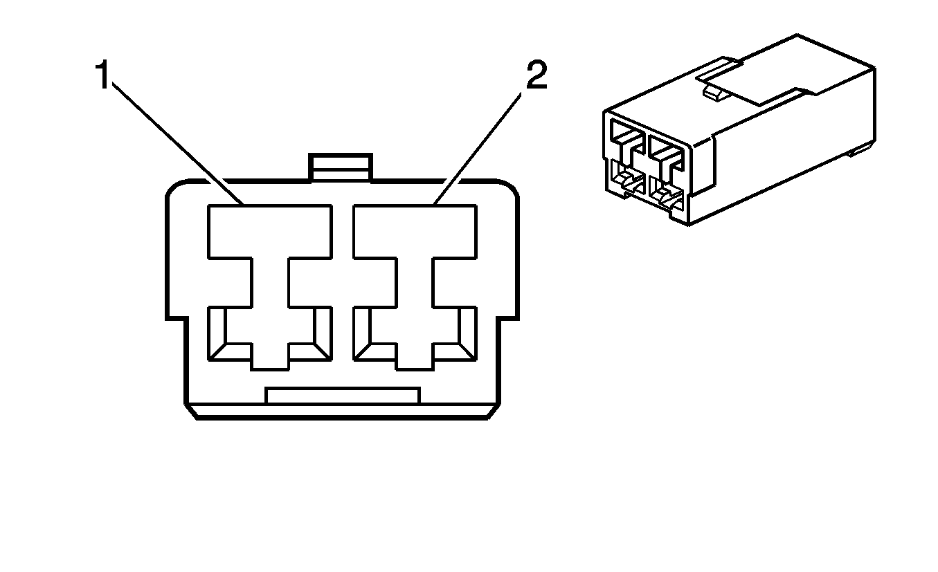
| Table 6: | Speaker - Left Rear |
| Table 7: | Speaker - Passenger Front |
| Table 8: | Speaker - Right Front Tweeter |
| Table 9: | Speaker - Right Rear |

| |||||||
|---|---|---|---|---|---|---|---|
Connector Part Information |
| ||||||
Pin | Wire Color | Circuit No. | Function | ||||
1 | BN | 117 | Right Front Speaker Output (-) | ||||
1 | BN | 117 | Right Front Speaker Output (-) | ||||
2 | WH/BK | 115 | Right Rear Speaker Output (-) | ||||
3 | PU | 309 | Right Park Lamp Supply Voltage | ||||
4 | YE | 43 | Accessory Voltage | ||||
5 | OG | 40 | Battery Positive Voltage | ||||
6 | -- | -- | Not Used | ||||
7 | GN | 116 | Left Rear Speaker Output (-) | ||||
8 | L-GN | 118 | Left Front Speaker Output (-) | ||||
8 | L-GN | 118 | Left Front Speaker Output (-) | ||||
9 | L-BU | 200 | Right Front Speaker Output (+) | ||||
9 | L-BU | 200 | Right Front Speaker Output (+) | ||||
10 | D-BU/WH | 46 | Right Rear Speaker Output (+) | ||||
11 | D-BU | 44 | Instrument Panel Lamps Dimming Control | ||||
12 | RD | 161 | Antenna Enable Signal | ||||
13 | D-BU/RD | 367 | Remote Radio Control Signal | ||||
14 | BK | 1050 | Ground (LHD) | ||||
BK | 450 | Ground (LHD) | |||||
15 | -- | -- | Not Used | ||||
16 | BN/WH | 368 | Remote Radio Control Low Reference | ||||
17 | GY | 199 | Left Rear Speaker Output (+) | ||||
18 | PU | 201 | Left Front Speaker Output (+) | ||||
18 | PU | 201 | Left Front Speaker Output (+) | ||||
19 | BK | 1550 | Ground (RHD) | ||||

| |||||||
|---|---|---|---|---|---|---|---|
Connector Part Information |
| ||||||
Pin | Wire Color | Circuit No. | Function | ||||
1 | WH/BK | 115 | Right Rear Speaker Output (-) | ||||
2 | D-BU/WH | 46 | Right Rear Speaker Output (+) | ||||
3 | BN | 117 | Right Front Speaker Output (-) | ||||
BN | 117 | Right Front Speaker Output (-) | |||||
4 | L-BU | 200 | Right Front Speaker Output (+) | ||||
L-BU | 200 | Right Front Speaker Output (+) | |||||
5 | L-GN | 118 | Left Front Speaker Output (-) | ||||
L-GN | 118 | Left Front Speaker Output (-) | |||||
6 | PU | 201 | Left Front Speaker Output (+) | ||||
PU | 201 | Left Front Speaker Output (+) | |||||
7 | D-GN | 116 | Left Rear Speaker Output (-) | ||||
8 | GY | 199 | Left Rear Speaker Output (+) | ||||
9 | PU | 309 | Right Park Lamp Supply Voltage | ||||
10-11 | -- | -- | Not Used | ||||
12 | OG | 40 | Battery Positive Voltage | ||||
13 | RD | 161 | Antenna Enable Signal | ||||
RD | 161 | Antenna Enable Signal | |||||
14 | D-BU | 44 | Instrument Panel Lamps Dimming Control | ||||
15 | YE | 43 | Accessory Voltage | ||||
16 | BK | 1550 | Ground | ||||

| |||||||
|---|---|---|---|---|---|---|---|
Connector Part Information |
| ||||||
Pin | Wire Color | Circuit No. | Function | ||||
1-10 | -- | -- | Not Used | ||||
11 | BN/WH | 368 | Remote Radio Conrol Low Reference | ||||
12 | D-BU/RD | 367 | Remote Radio Control Signal | ||||
13-20 | -- | -- | Not Used | ||||

| |||||||
|---|---|---|---|---|---|---|---|
Connector Part Information |
| ||||||
Pin | Wire Color | Circuit No. | Function | ||||
1 | PU | 201 | Left Front Speaker Output (+) | ||||
2 | L-GN | 118 | Left Front Speaker Output (-) | ||||

| |||||||
|---|---|---|---|---|---|---|---|
Connector Part Information |
| ||||||
Pin | Wire Color | Circuit No. | Function | ||||
1 | PU | 201 | Left Front Speaker Output (+) | ||||
2 | L-GN | 118 | Left Front Speaker Output (-) | ||||

| |||||||
|---|---|---|---|---|---|---|---|
Connector Part Information |
| ||||||
Pin | Wire Color | Circuit No. | Function | ||||
1 | YE/D-BU | 199 | Left Rear Speaker Output (+) | ||||
2 | BN | 116 | Left Rear Speaker Output (-) | ||||

| |||||||
|---|---|---|---|---|---|---|---|
Connector Part Information |
| ||||||
Pin | Wire Color | Circuit No. | Function | ||||
1 | L-BU | 200 | Right Front Speaker Output (+) | ||||
2 | BN | 117 | Right Front Speaker Output (-) | ||||

| |||||||
|---|---|---|---|---|---|---|---|
Connector Part Information |
| ||||||
Pin | Wire Color | Circuit No. | Function | ||||
1 | L-BU | 200 | Right Front Speaker Output (+) | ||||
2 | BN | 117 | Right Front Speaker Output (-) | ||||

| |||||||
|---|---|---|---|---|---|---|---|
Connector Part Information |
| ||||||
Pin | Wire Color | Circuit No. | Function | ||||
1 | BK | 46 | Right Rear Speaker Output (+) | ||||
2 | D-BU | 115 | Right Rear Speaker Output (-) | ||||
