Removal Procedure
- Disconnect the negative battery cable and let the vehicle sit for 1 minute to deactivate the air bag.
- Remove the upper and the lower steering column cover by removing the screws.
- Remove the lower instrument trim panel.
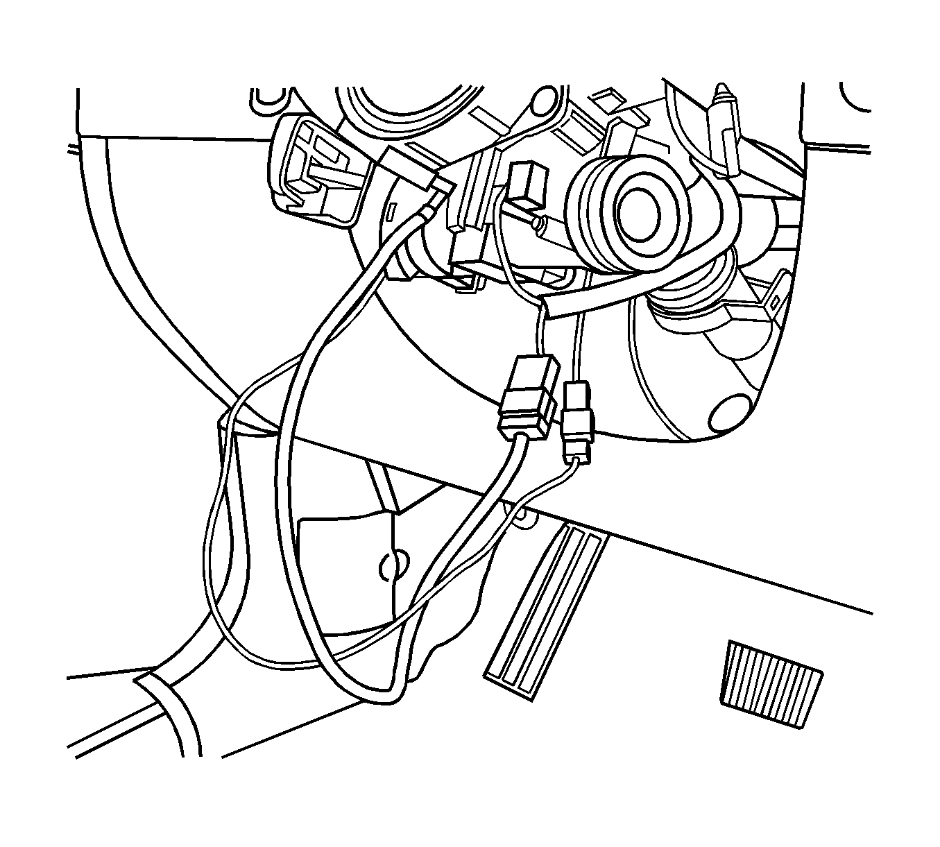
- Disconnect the air bag electrical connections.
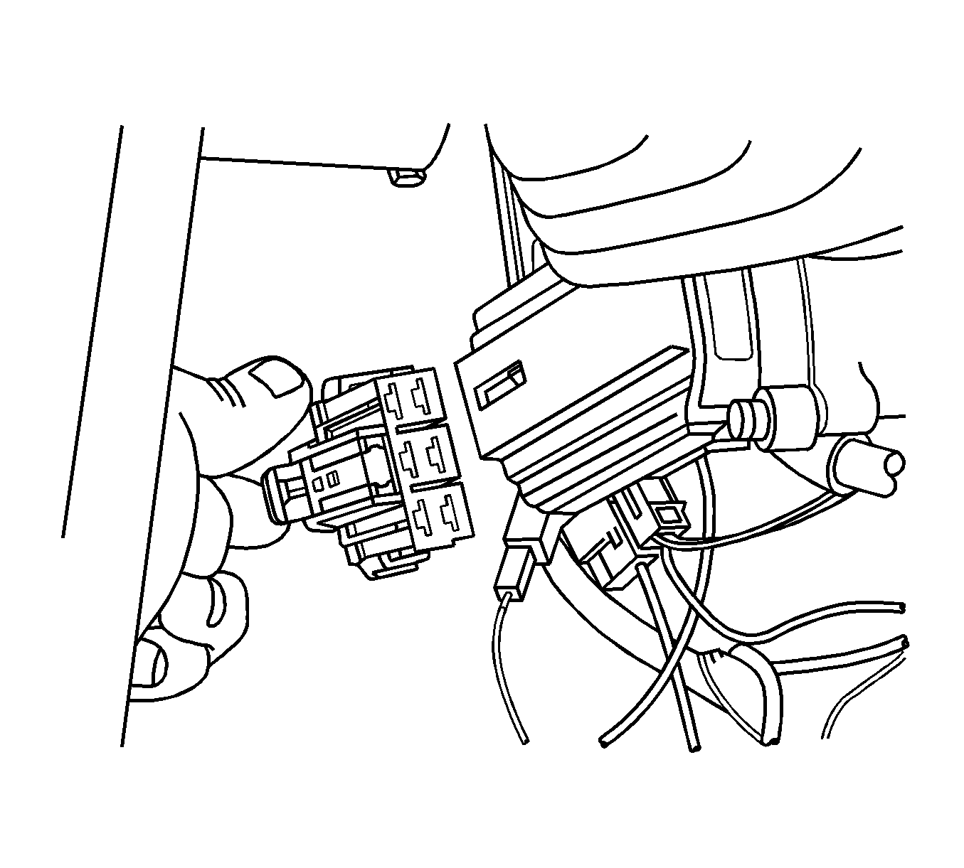
- Remove the immobilizer module, if equipped. Refer to Theft Deterrent Module Replacement
- Disconnect the ignition switch electrical connection.
- Adjust the steering to the straight-ahead position.
- Make a mark on the steering column shaft that lines up with a mark on the intermediate shaft upper universal joint.
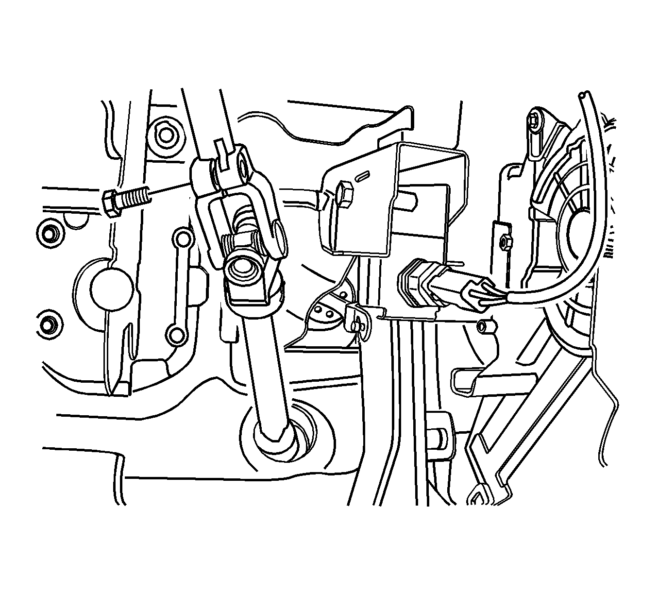
- Remove the pinch bolt from the intermediate shaft universal joint.
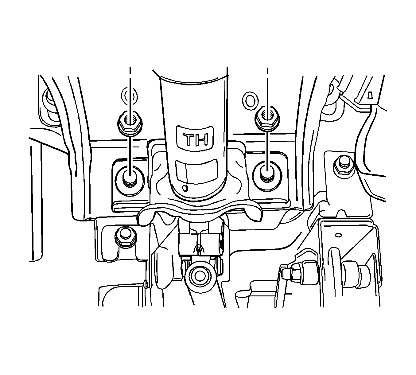
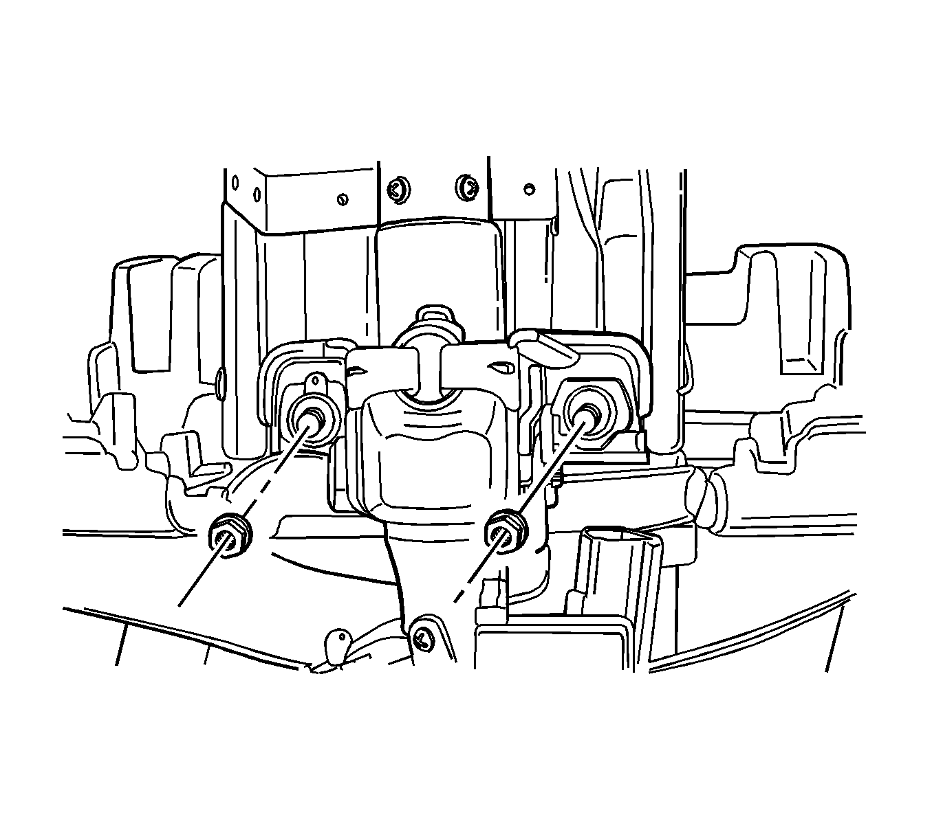
- Remove the steering column lower mounting nuts.
- Remove the steering column upper mounting nuts that hold the rear bracket of the steering column jacket assembly.
- Guide the steering column assembly out of the steering shaft flange and carefully lay down the assembly.
Caution: Refer to Battery Disconnect Caution in the Preface section.
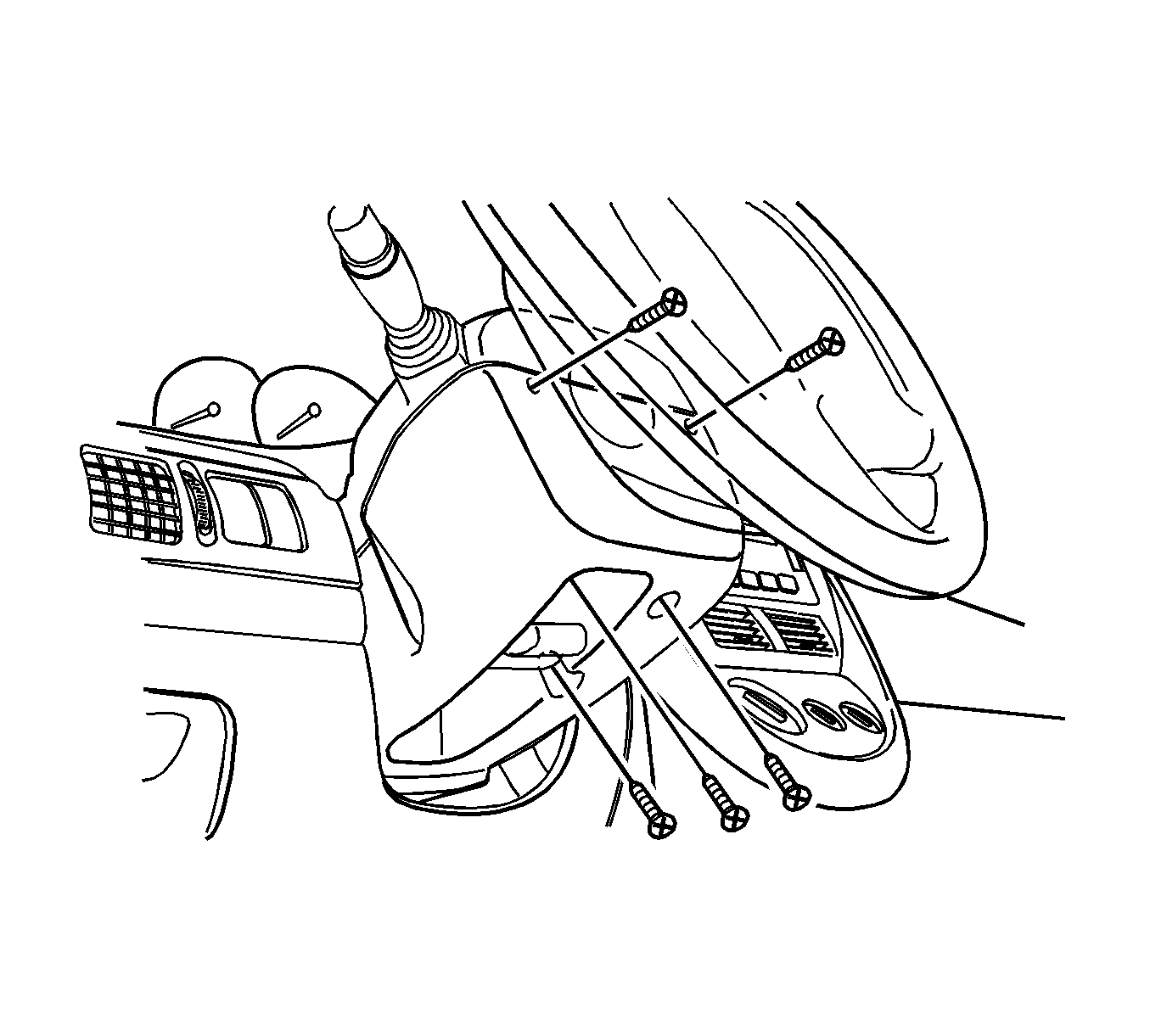
Notice: The front wheels of the vehicle must be maintained in the straight ahead position and the steering column must be in the LOCK position before disconnecting the steering column or intermediate shaft. Failure to follow these procedures will cause improper alignment of some components during installation and result in damage to the SIR coil assembly.
Notice: Once the steering column is removed from the vehicle, the column is extremely susceptible to damage. Dropping the column assembly on the end could collapse the steering shaft or loosen the plastic injections, which maintain column rigidity. Leaning on the column assembly could cause the jacket to bend or deform. Any of the above damage could impair the columns collapsible design. Do NOT hammer on the end of the shaft, because hammering could loosen the plastic injections, which maintain column rigidity. If you need to remove the steering wheel, refer to the Steering Wheel Replacement procedure in this section.
Important: Remove the steering column only if the following conditions exist:
• The steering column requires replacement. • The steering and the ignition lock housing require replacement. • Another operation requires the removal of the steering column.
Installation Procedure
- Install the steering column assembly into the steering shaft flange.
- Install the steering column upper mounting nut.
- Install the steering column lower mounting nuts.
- Install the pinch bolt into the intermediate shaft universal joint.
- Connect the ignition switch electrical connection.
- Connect the immobilizer module, if equipped. Refer to Theft Deterrent Module Replacement
- Connect the air bag electrical connections.
- Install the lower instrument trim panel.
- Install the upper and lower steering column screws.
- Connect the negative battery cable.

Important: When installing, ensure the steering wheel spokes are centered diagonally and pointed downward while the front wheels are positioned in the straight ahead position.
Important: Do not let the steering column assembly hang unsupported.
Notice: Refer to Fastener Notice in the Preface section.
Tighten
Tighten the nut to 23 N·m (17 lb ft).

Tighten
Tighten the nuts to 23 N·m (17 lb ft).

Tighten
Tighten the bolt to 22 N·m (16 lb ft).


