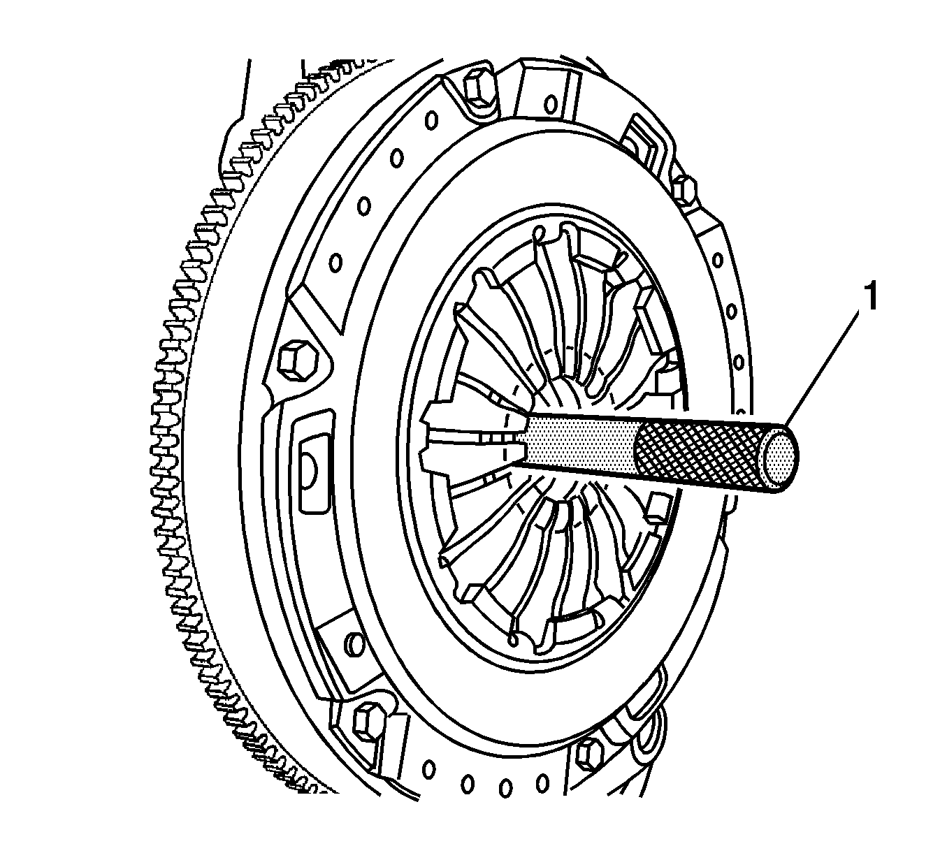
For 1990-2009 cars only
Tools Required
| • | J 36547 Input Shaft Seal Installer |
| • | J 42474 Clutch Arbor or Equivalent |
Removal Procedure
- Disconnect the negative battery cable.
- Raise and suitably support the vehicle. Refer to Lifting and Jacking the Vehicle in General Information.
- Remove the left front wheel. Refer to Tire and Wheel Removal and Installation in Tires and Wheels.
- Remove the transaxle from the vehicle. Refer to Transmission Replacement in Manual Transmission.
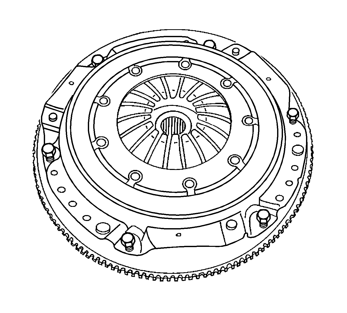
- Remove the pressure plate bolts and the pressure plate. Support the pressure plate when you remove the last bolt.
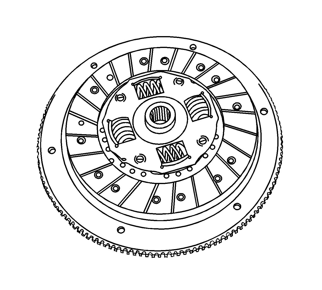
- Remove the clutch disc.
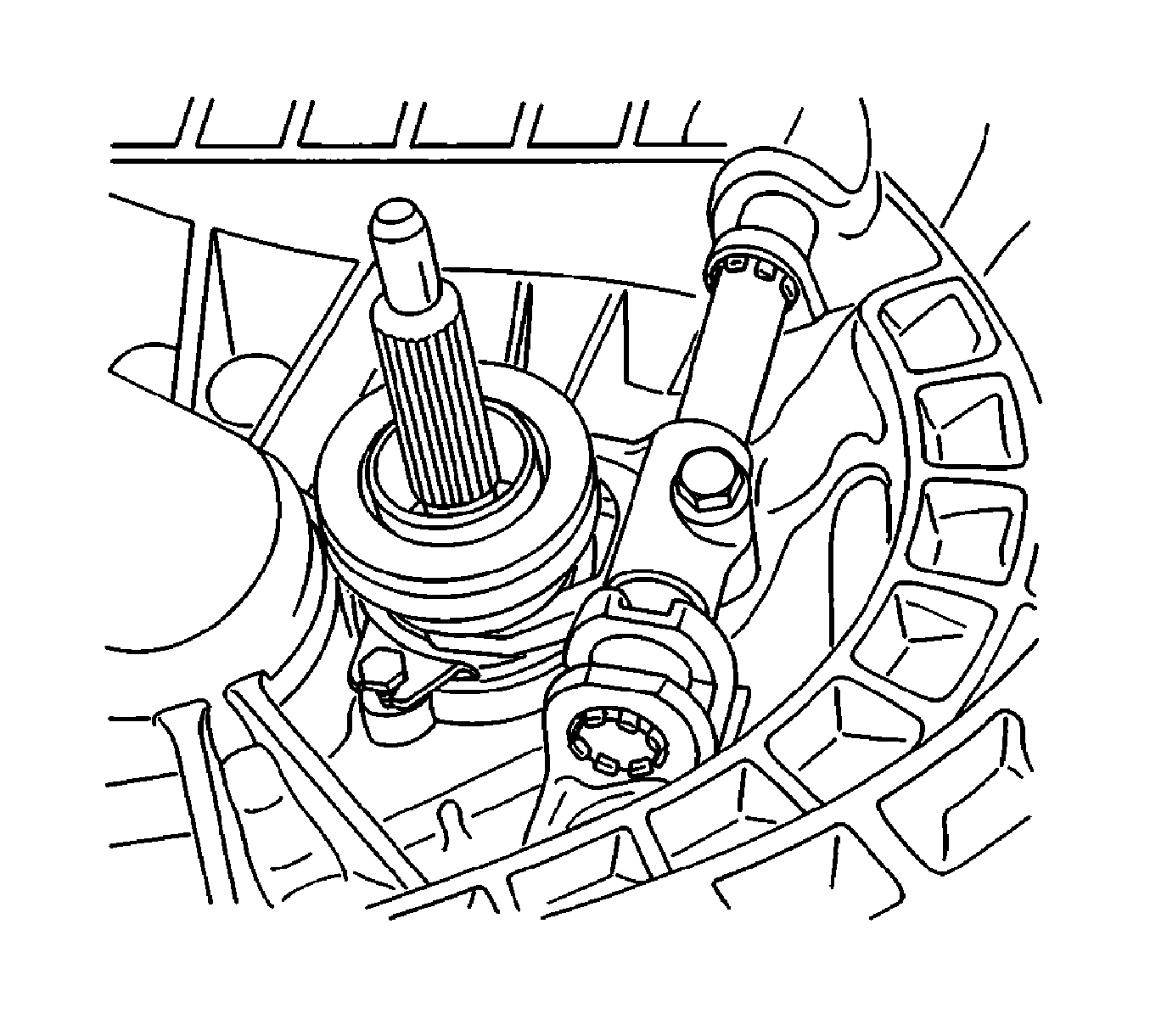
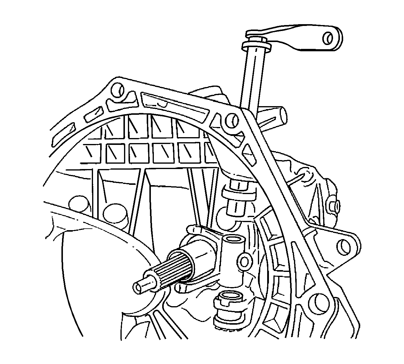
- Remove the release fork bolt.
- Pull the clutch release shaft upward, out of the transaxle.
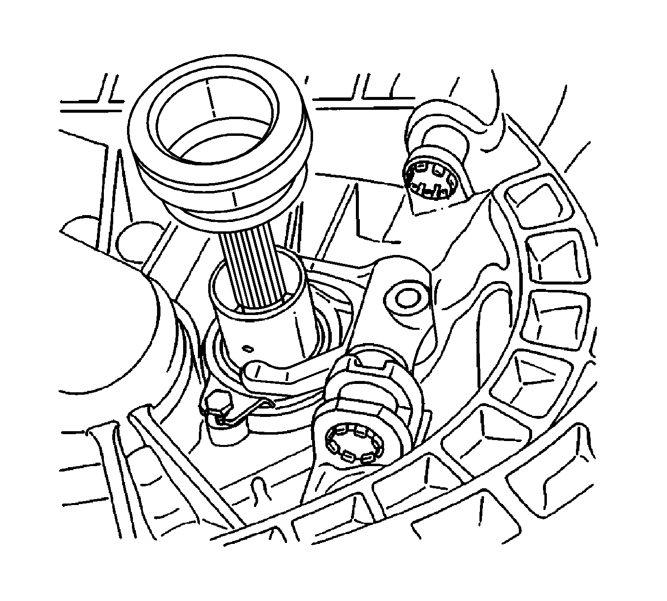
- Remove the fork and the release bearing from the release bearing guide sleeve.
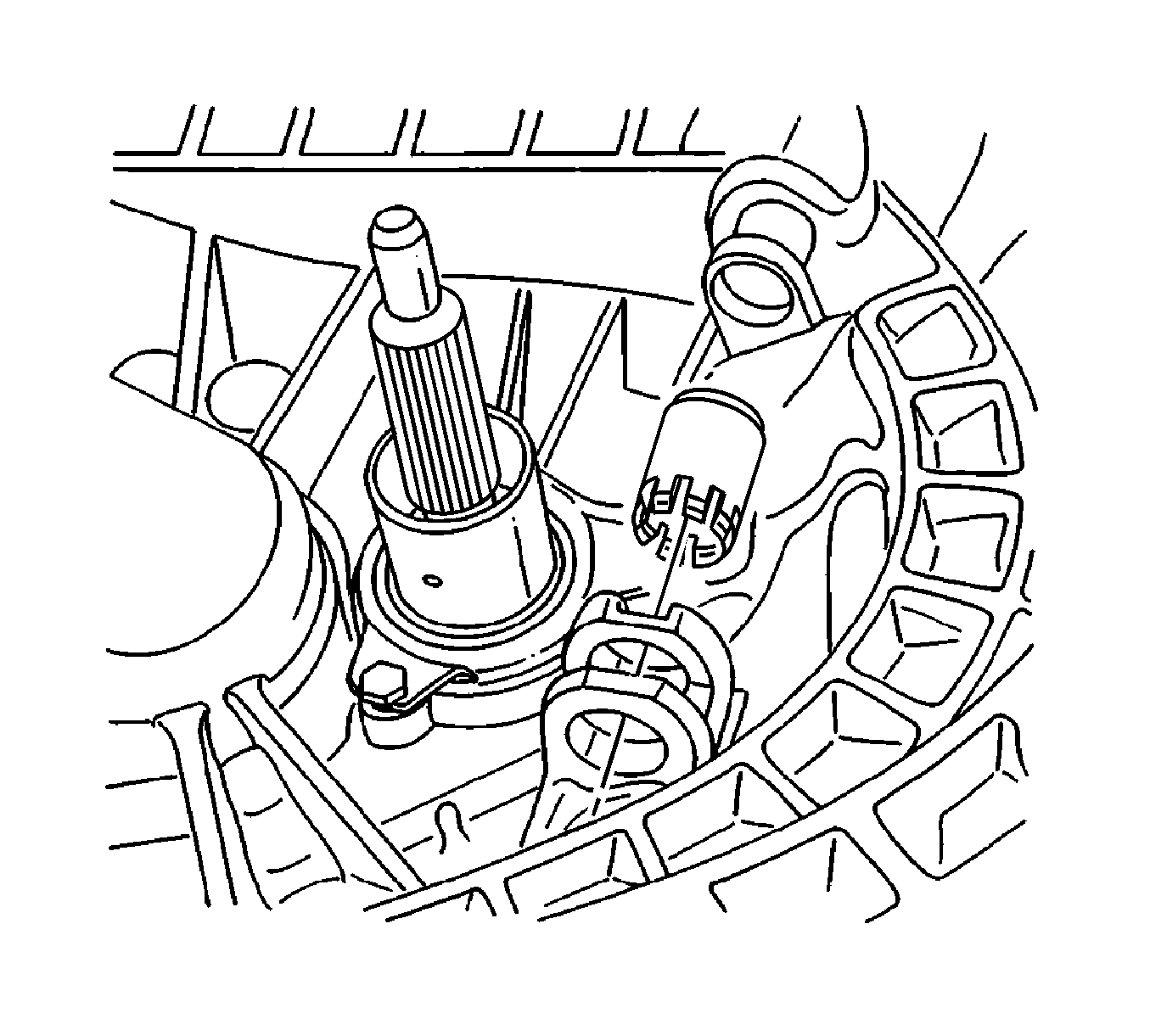
- Remove the release lever shaft bushings.
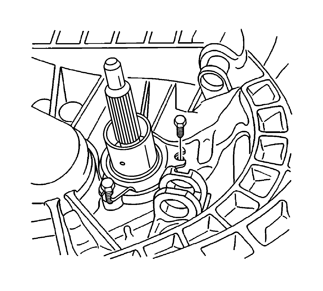
- Remove the release bearing guide sleeve bolts and the release bearing guide sleeve.
- Remove the input shaft seal from the release bearing guide sleeve.
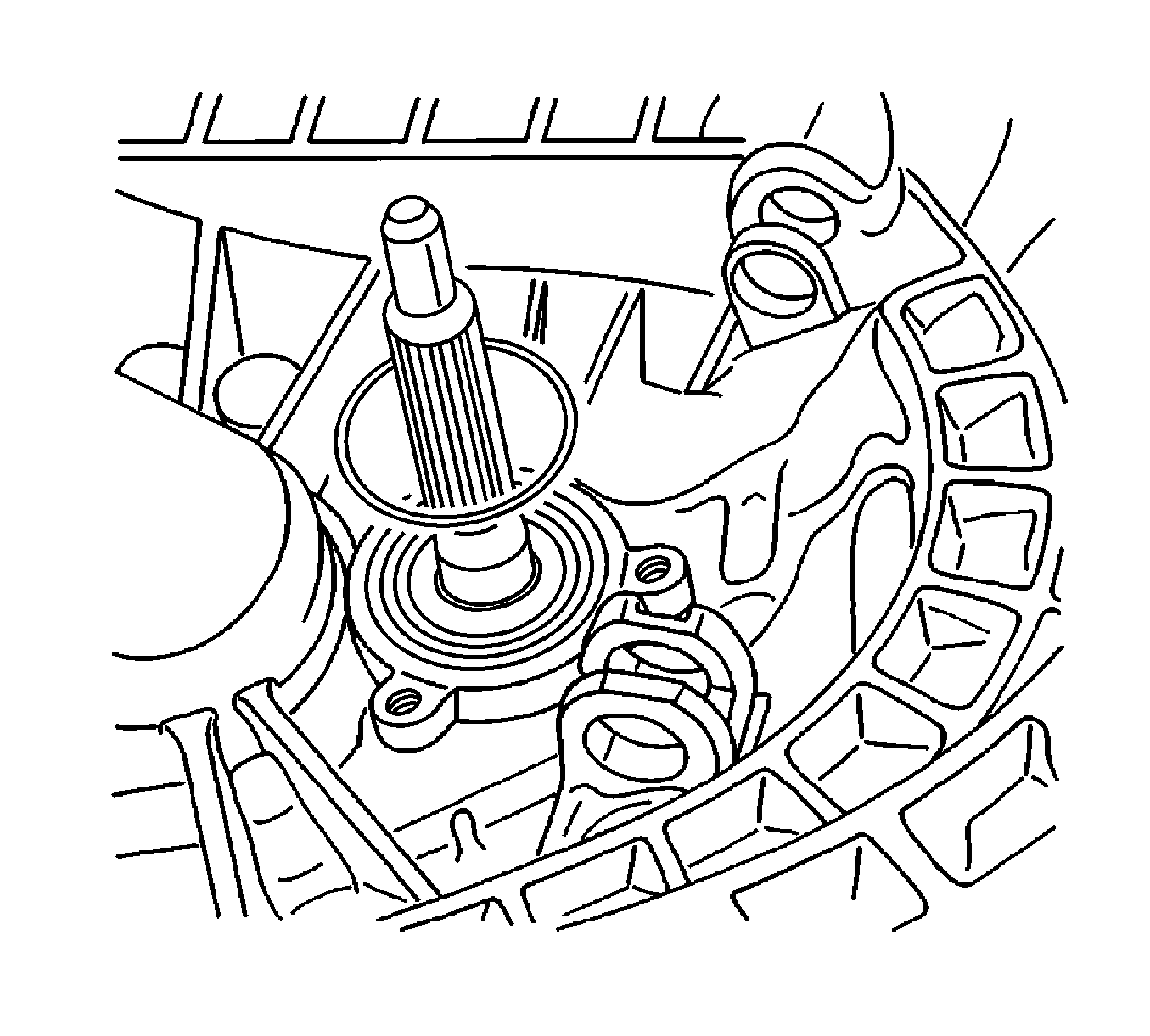
- Remove the O-ring from the groove in the transaxle case.
Caution: Refer to Battery Disconnect Caution in the Preface section.
Installation Procedure
- Install the O-ring to the groove in the transaxle case.
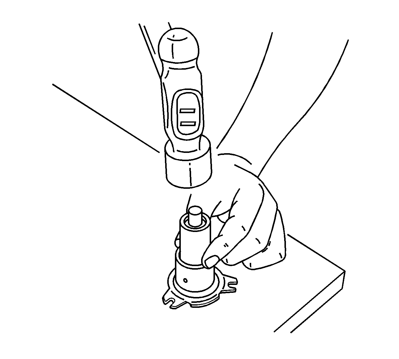
- Using J 36547 with a hammer, install the input shaft seal into the release bearing guide sleeve.
- Coat the sleeve surface with multi-purpose grease.
- Install the release bearing guide sleeve bolts and release bearing guide sleeve.
- Coat the bushing borer with multi-purpose grease.
- Install the release lever shaft bushings.
- Coat the release bearing bore with multi-purpose grease.
- Install the fork and the release bearing to the release bearing guide sleeve.
- Push the clutch release shaft downward, into the transaxle.
- Install the release fork bolt.
- Coat the spline on the clutch disc with multi-purpose grease.
- Install the clutch disc.
- Align the pressure plate and the clutch disc onto the flywheel using J 42474 .
- Install the pressure plate bolts and the pressure plate.
- Install the transaxle to the vehicle. Refer to Transmission Replacement in Manual Transmission.
- Install the left front wheel. Refer to Tire and Wheel Removal and Installation in Tires and Wheels.
- Connect the negative battery cable.


Notice: Refer to Fastener Notice in the Preface section.
Tighten
Tighten the release bearing guide sleeve bolts to 5 N·m (45 lb in).


Tighten
Tighten the release fork bolt to 35 N·m (26 lb ft).

