Caution: Always refer to the Diagnostic Trouble Code (DTC) listing information before diagnosing the SIR system. Failure to follow the listed information may result in an unintended Airbag deployment which could cause personal injury or vehicle damage.
Diagnostic Illustration 1
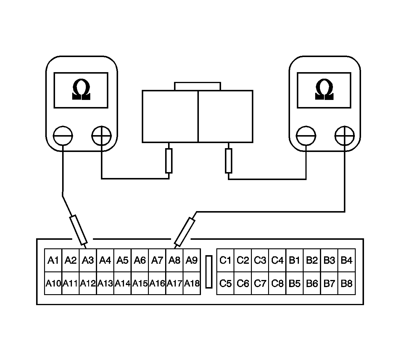
Checking the continuity between the passenger airbag and the sensing and diagnostic module (SDM).
Diagnostic Illustration 2
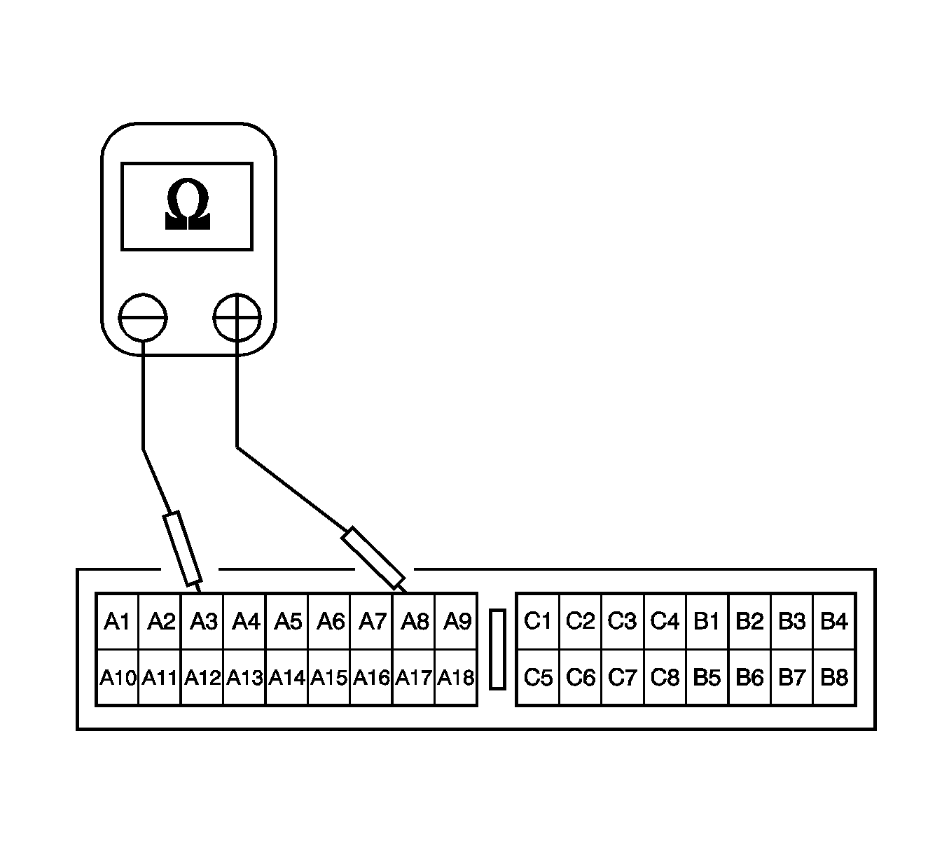
Checking for a short circuit between the passenger high and low circuits.
Diagnostic Illustration 3
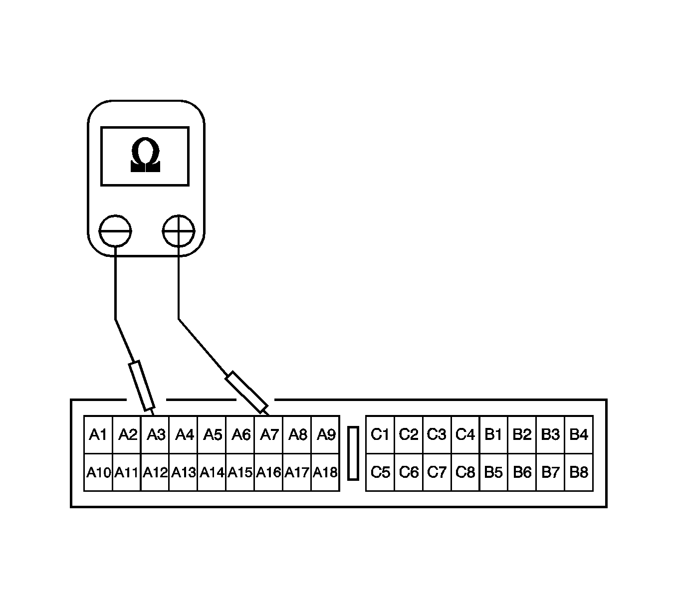
Checking for a short circuit between the passenger high and driver low circuits.
Diagnostic Illustration 4
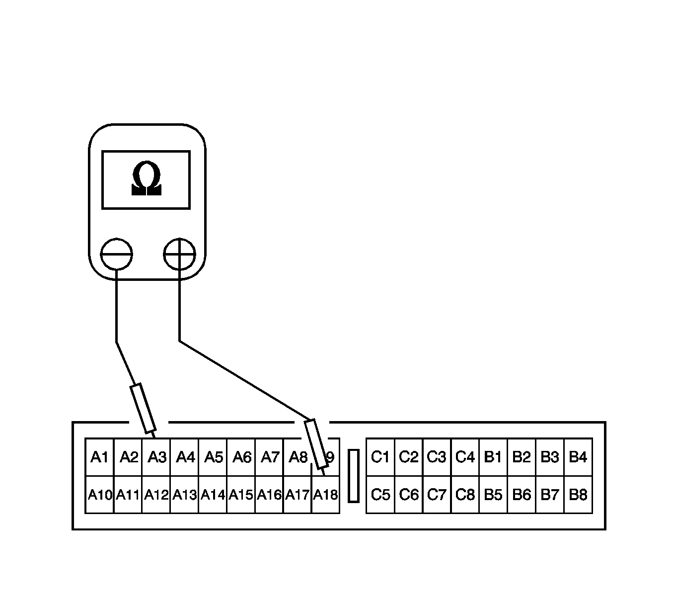
Checking for a short circuit between the passenger high circuit and ground.
Diagnostic Illustration 5
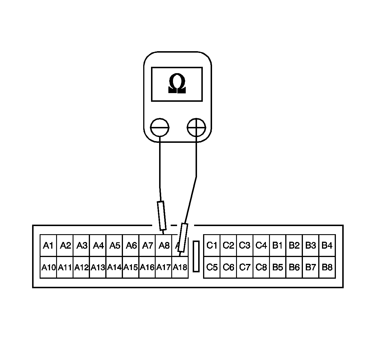
Checking for a short circuit between the passenger low circuit and ground.
Diagnostic Illustration 6
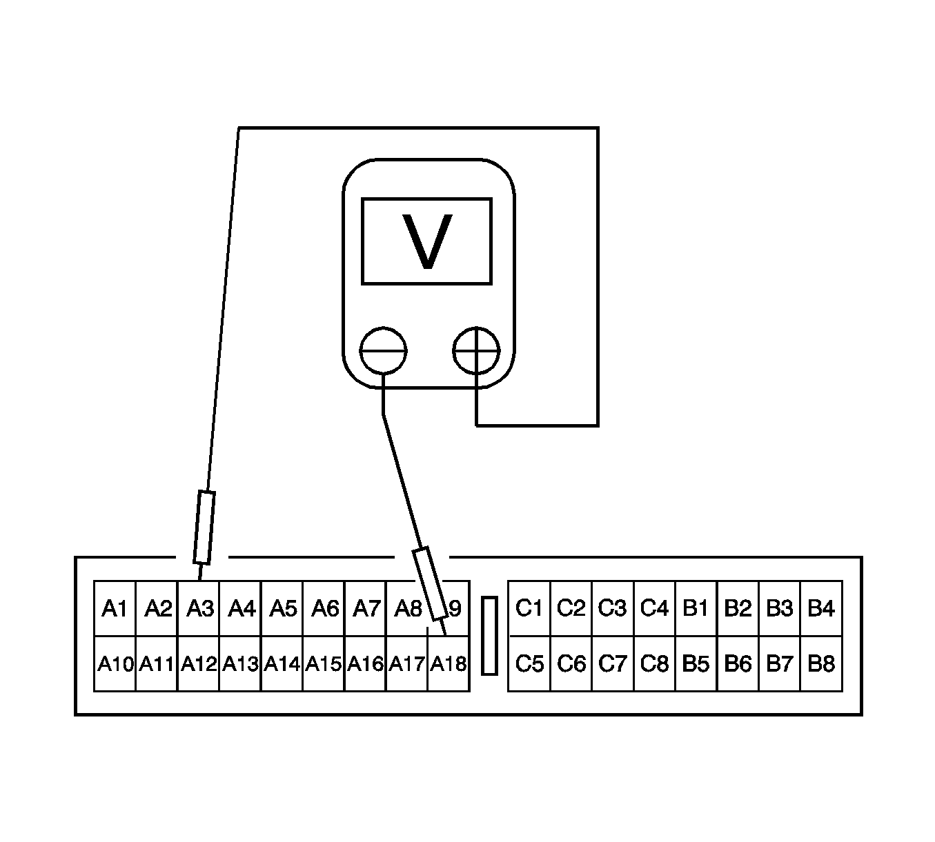
Checking for a short circuit between the passenger high circuit and voltage.
Diagnostic Illustration 7
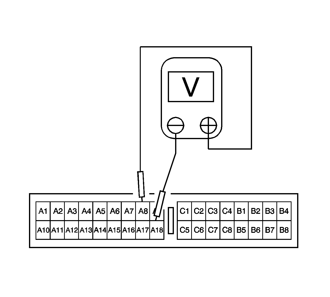
Checking for a short circuit between the passenger low circuit and voltage.
Diagnostic Illustration 8
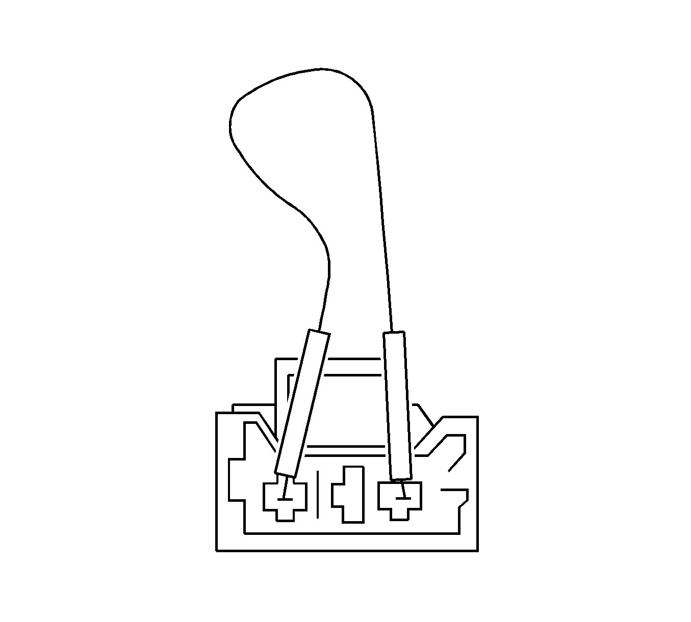
Placing a jumper on the SDM side of the yellow clock spring connector.
Diagnostic Illustration 9
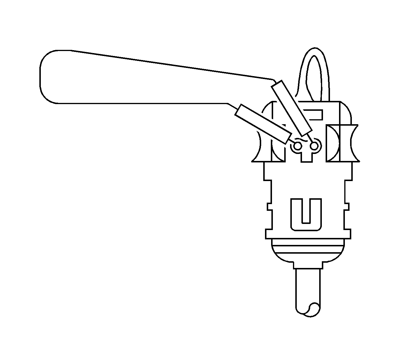
Placing a jumper on the clock spring-to-airbag connector.
Diagnostic Illustration 10
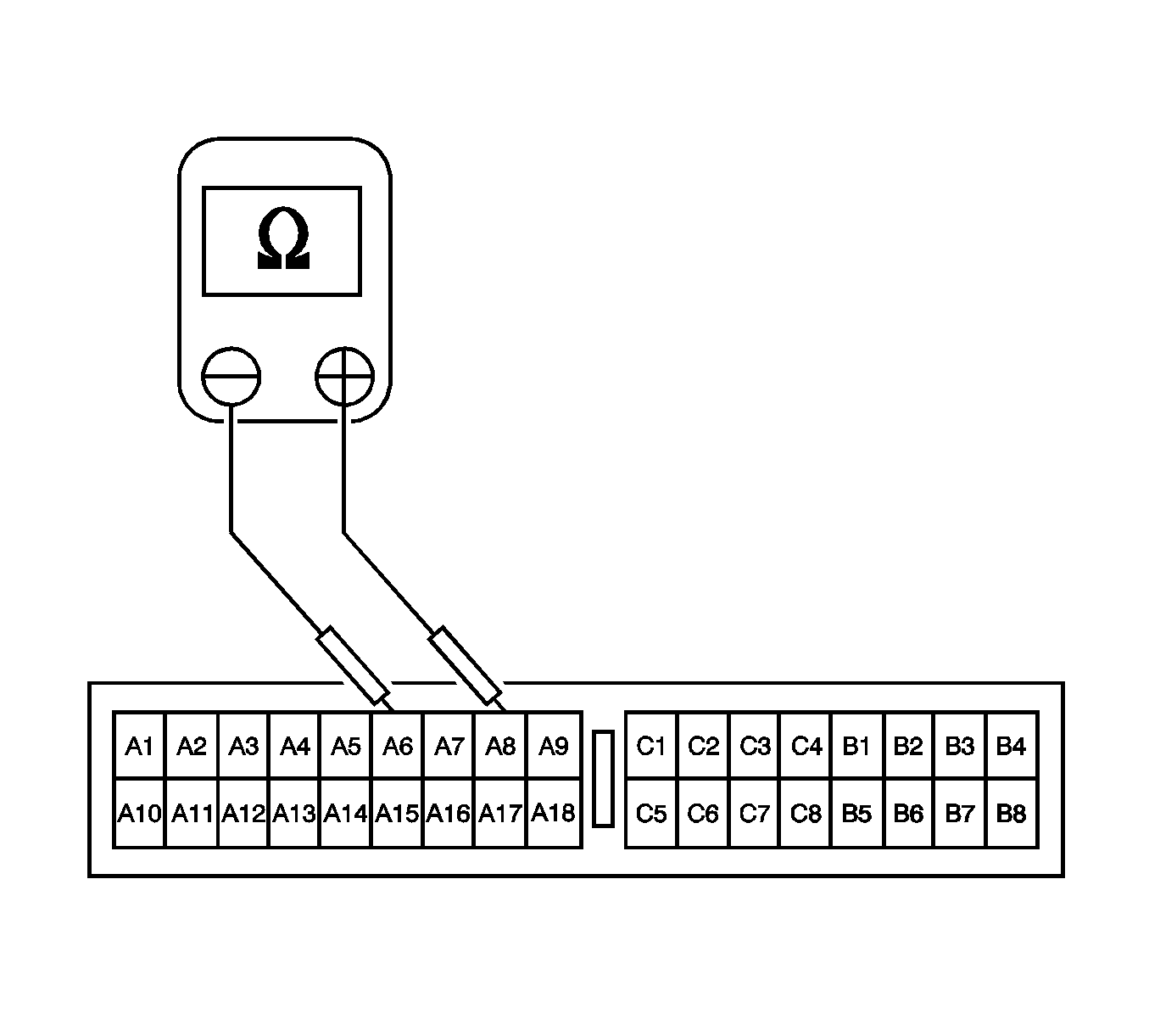
Checking for a short circuit between the driver high and passenger low circuits.
Diagnostic Illustration 11
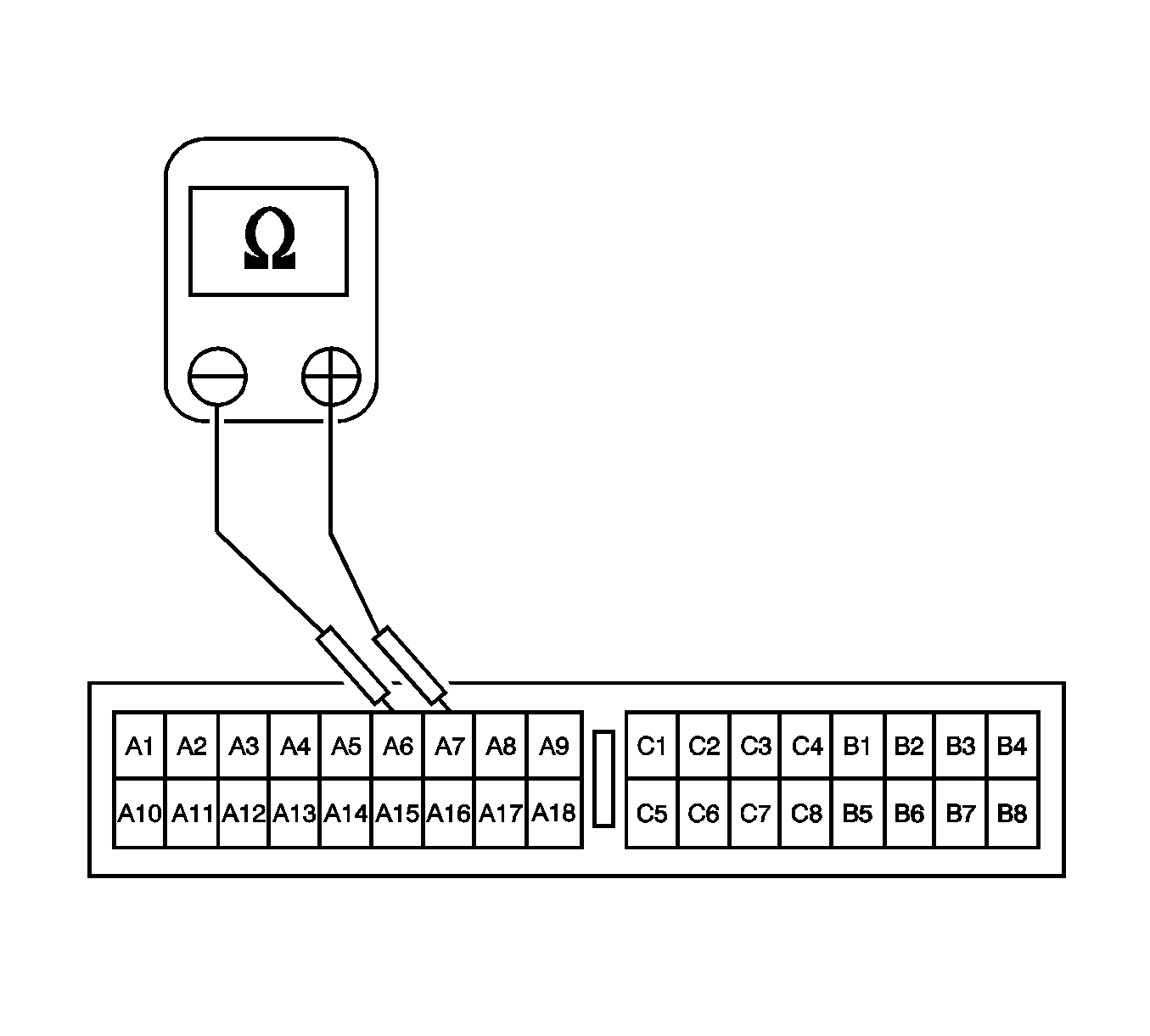
Checking for a short circuit between the driver high and driver low circuits.
Diagnostic Illustration 12
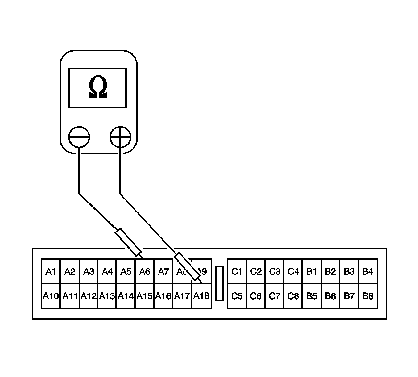
Checking for a short circuit between the driver high circuit and ground.
Diagnostic Illustration 13
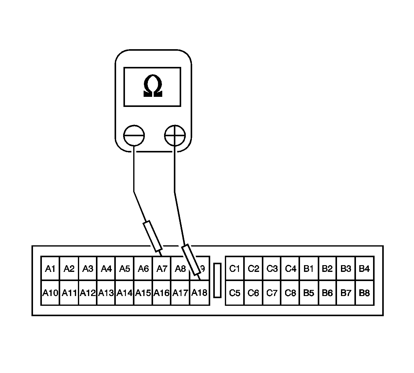
Checking for a short circuit between the driver low circuit and ground.
Diagnostic Illustration 14
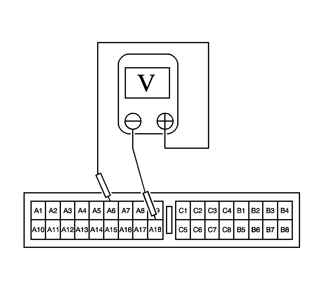
Checking for a short circuit between the driver high circuit and voltage.
Diagnostic Illustration 15
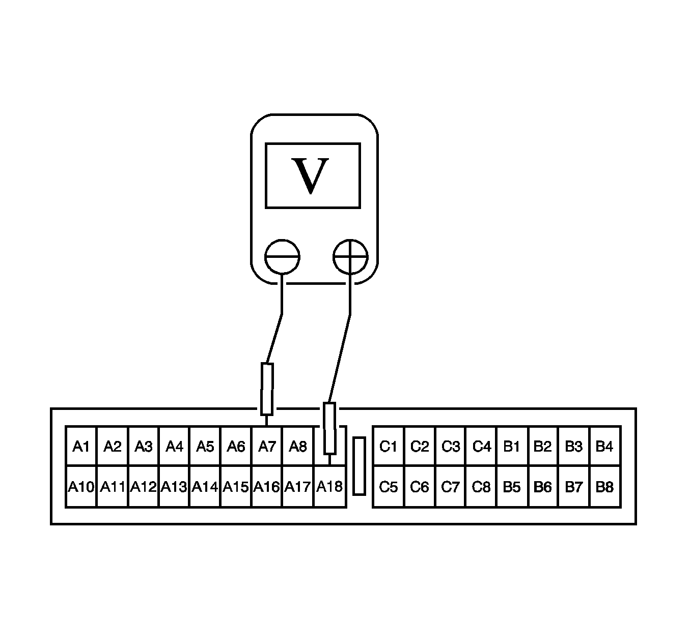
Checking for a short circuit between the driver low circuit and voltage.
Diagnostic Illustration 16
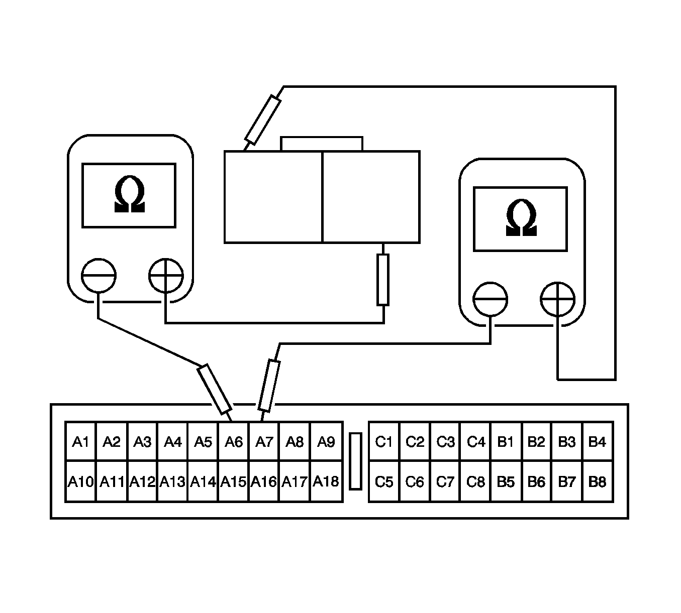
Checking for an open circuit between the sensing and diagnostic module (SDM) and the clock spring.
Diagnostic Illustration 17
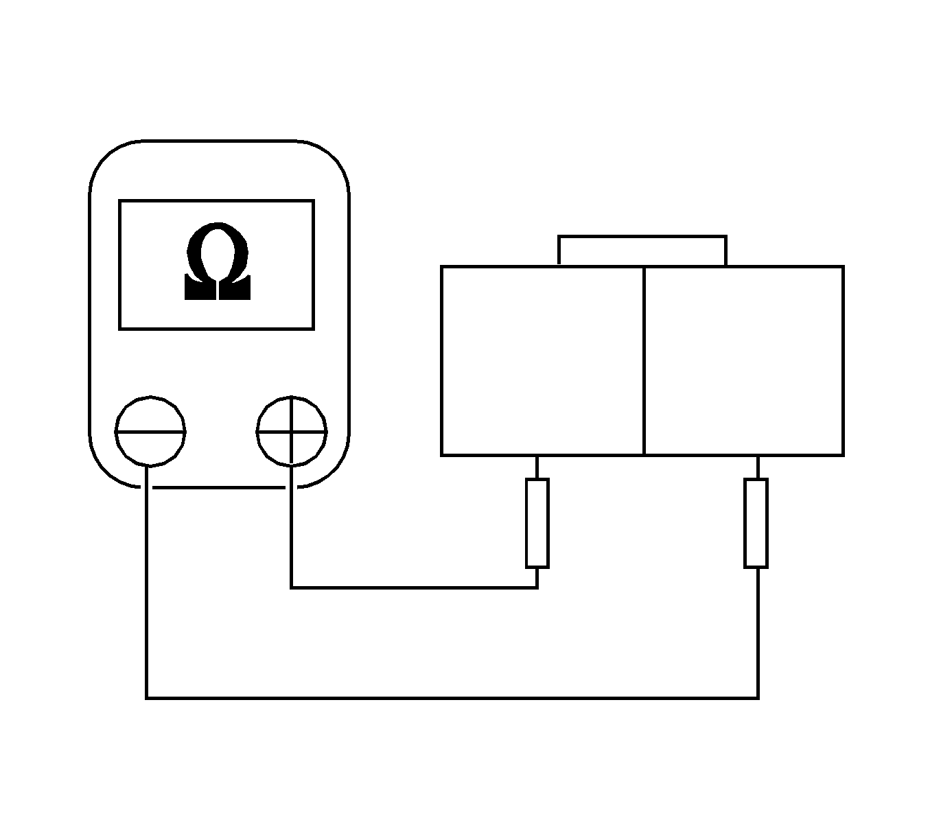
Checking for a short circuit between the right or left pretensioner high and low circuits.
Diagnostic Illustration 18
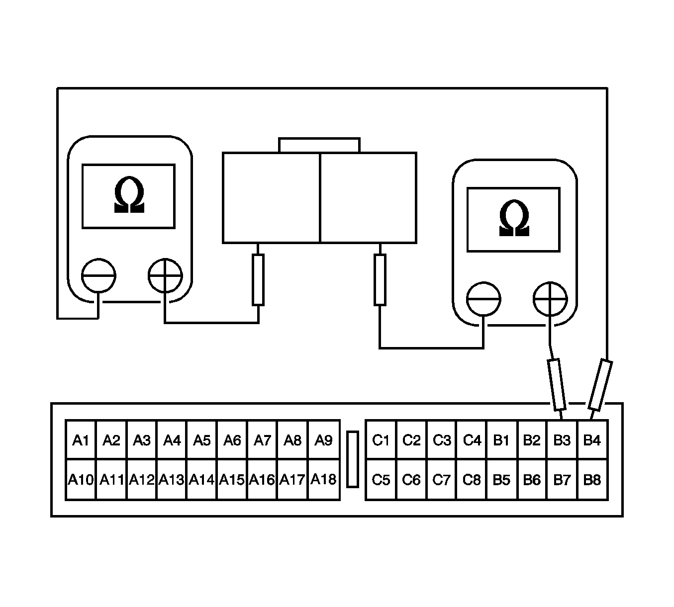
Checking for a continuity between the right side belt pretensioner and the sensing and diagnostic module (SDM).
Diagnostic Illustration 19
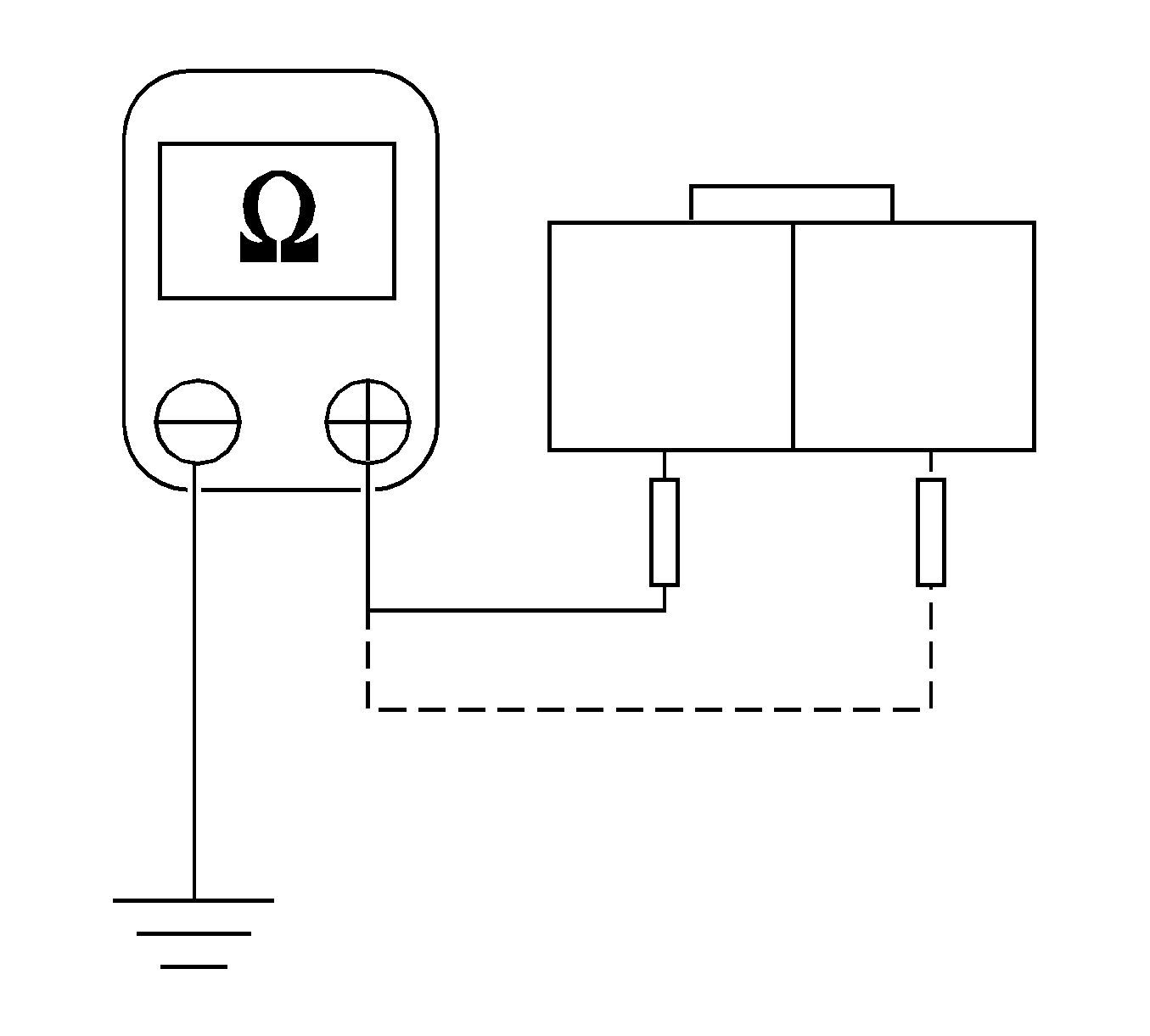
Checking for a short circuit between the wiring harness of right or left side belt pretensioner and ground.
Diagnostic Illustration 20
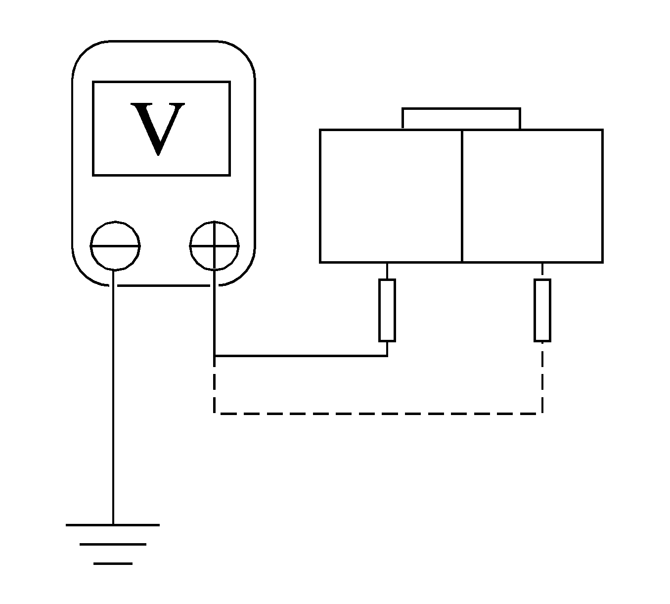
Checking for a short circuit between the belt pretensioner wiring harness and the voltage.
Diagnostic Illustration 21
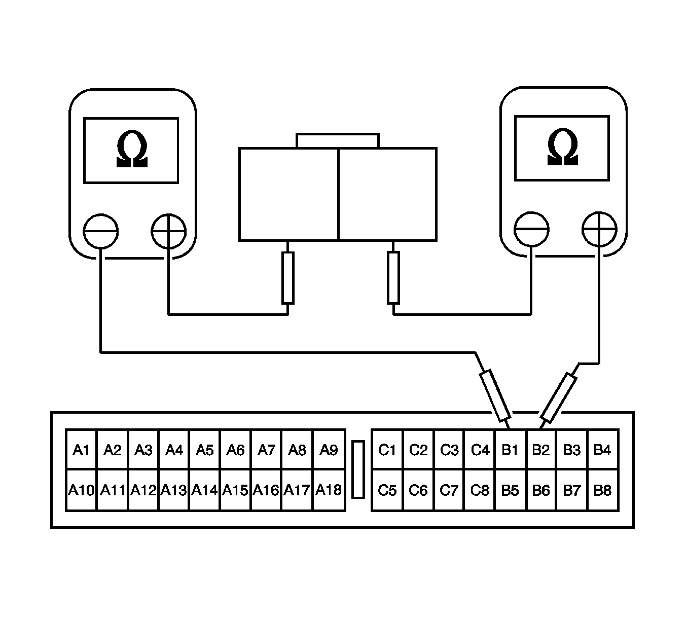
Checking for the continuity between the left side belt pretensioner and the sensing and diagnostic module (SDM).
