For 1990-2009 cars only
Removal Procedure
- Remove the fuel pump fuse.
- Start the engine. After it stalls, crank the engine for 10 seconds to rid the fuel system of fuel pressure.
- Disconnect the negative battery cable.
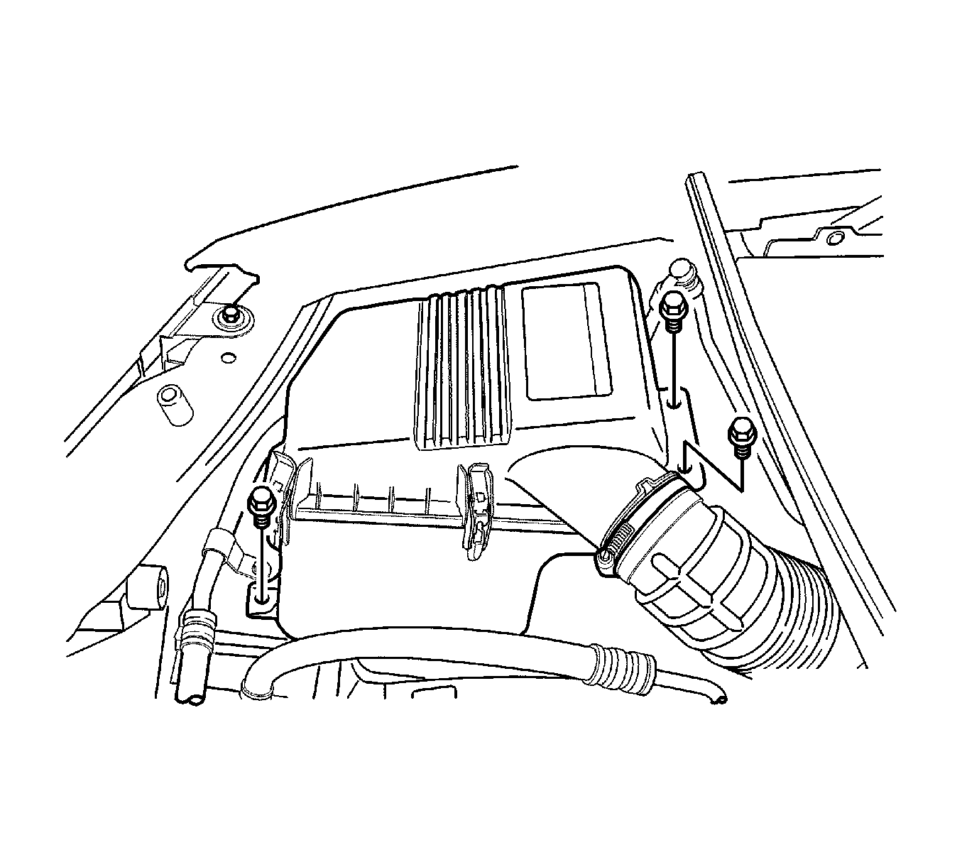
- Remove the air filter housing bolts.
- Remove the air filter housing assembly.
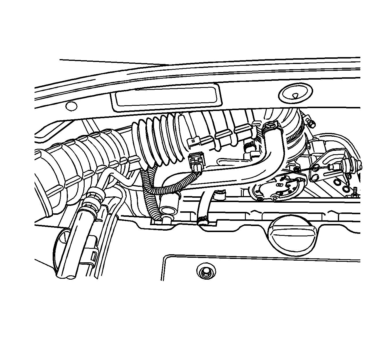
- Disconnect the manifold air temperature (MAT) sensor connector.
- Disconnect the breather hose from the valve cover.
- Remove the air intake tube from the throttle body.
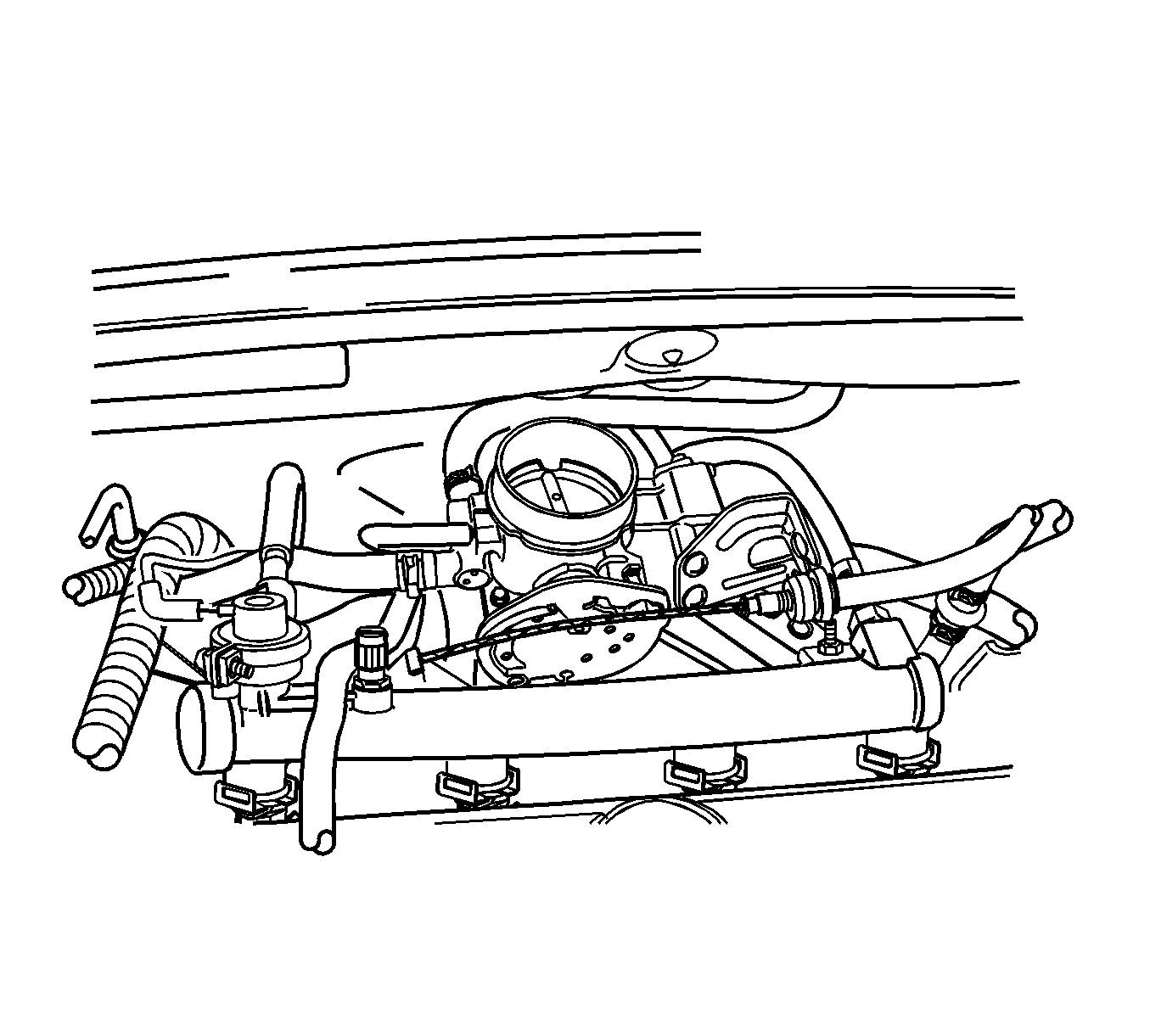
- Disconnect the throttle cable from the throttle body and the intake manifold.
- Disconnect the vacuum hose at the fuel pressure regulator.
- Remove the fuel injector rail and fuel injectors as an assembly.
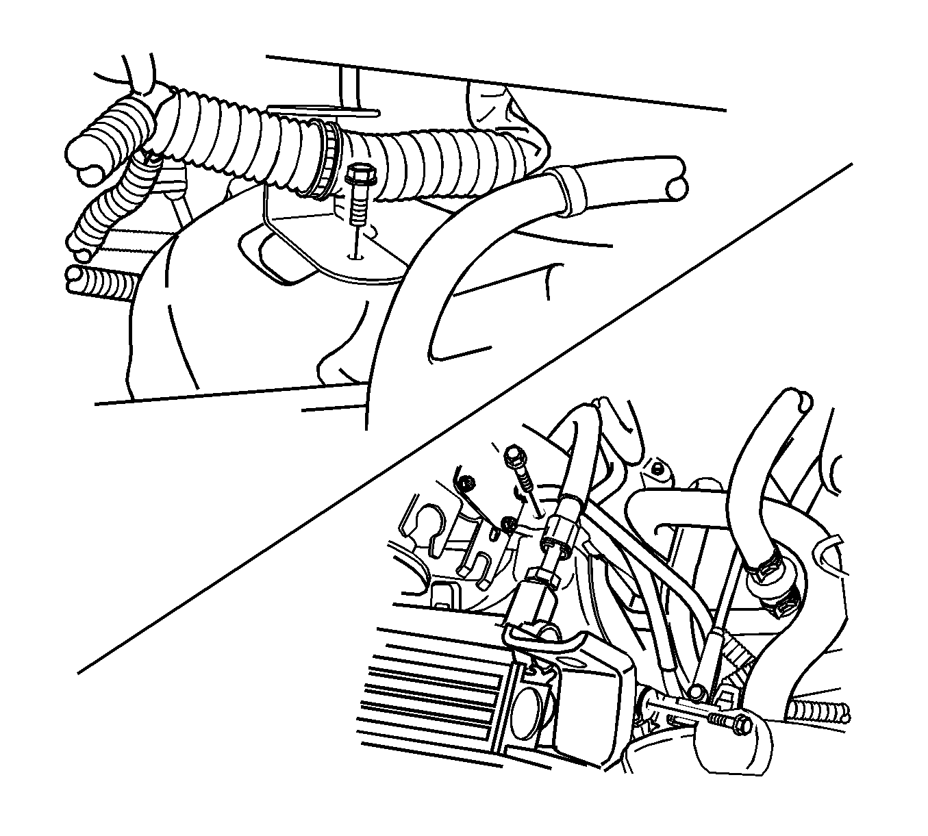
- Remove the engine harness wire bracket bolts from the rear of the intake manifold.
- Remove the evaporative emission (EVAP) canister purge solenoid bracket bolt and reposition the canister purge solenoid clear of the repair area.
- Remove the alternator upper bracket colts.
- Remove the alternator upper bracket.
- Disconnect the brake vacuum hose from the intake manifold.
- Remove the engine control module (ECM) ground terminal bolt from the intake manifold.
- Remove the intake manifold support bracket upper bolt to the intake manifold.
- Remove the throttle body assembly. Refer to Throttle Body Assembly Replacement .
- Remove the valve cover. Refer to Valve Rocker Arm Cover Replacement .
- Remove the intake manifold retaining bolt/nuts in the sequence shown.
- Remove the intake manifold gasket.
- Clean the sealing surfaces of the intake manifold and the cylinder head.
Caution: Refer to Battery Disconnect Caution in the Preface section.
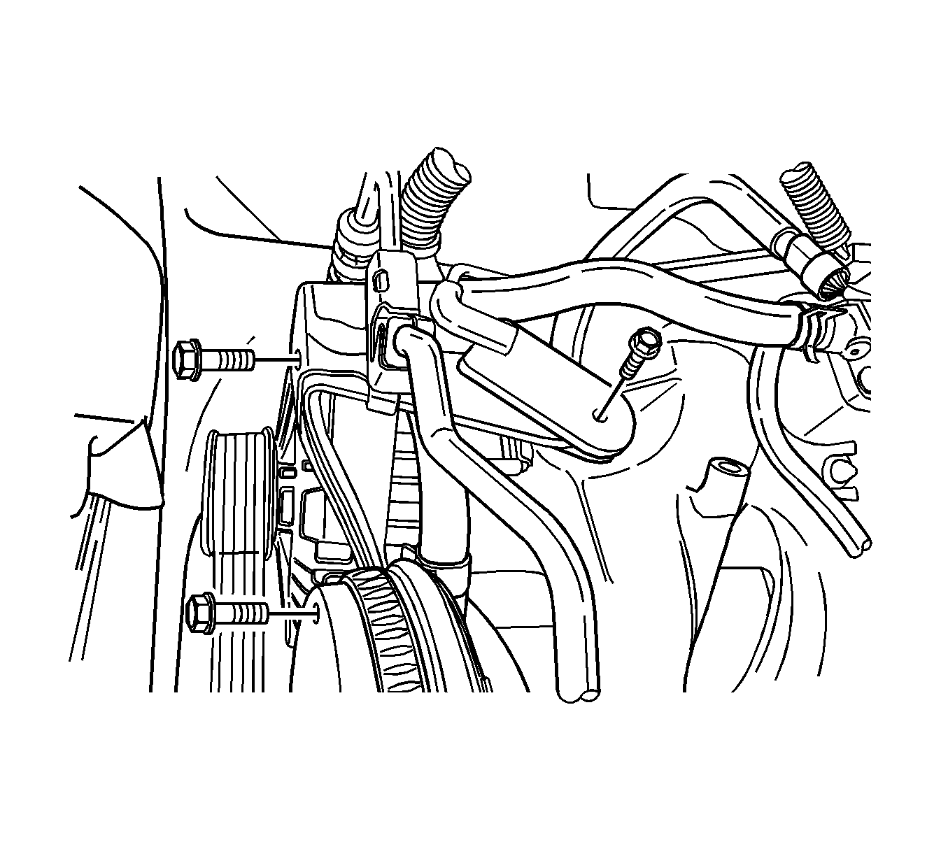
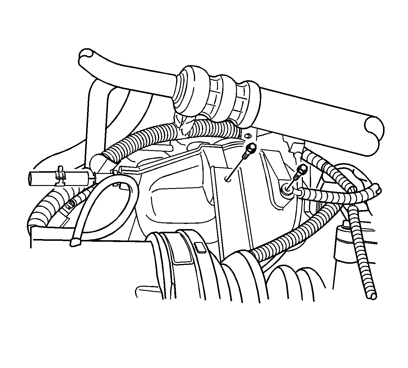
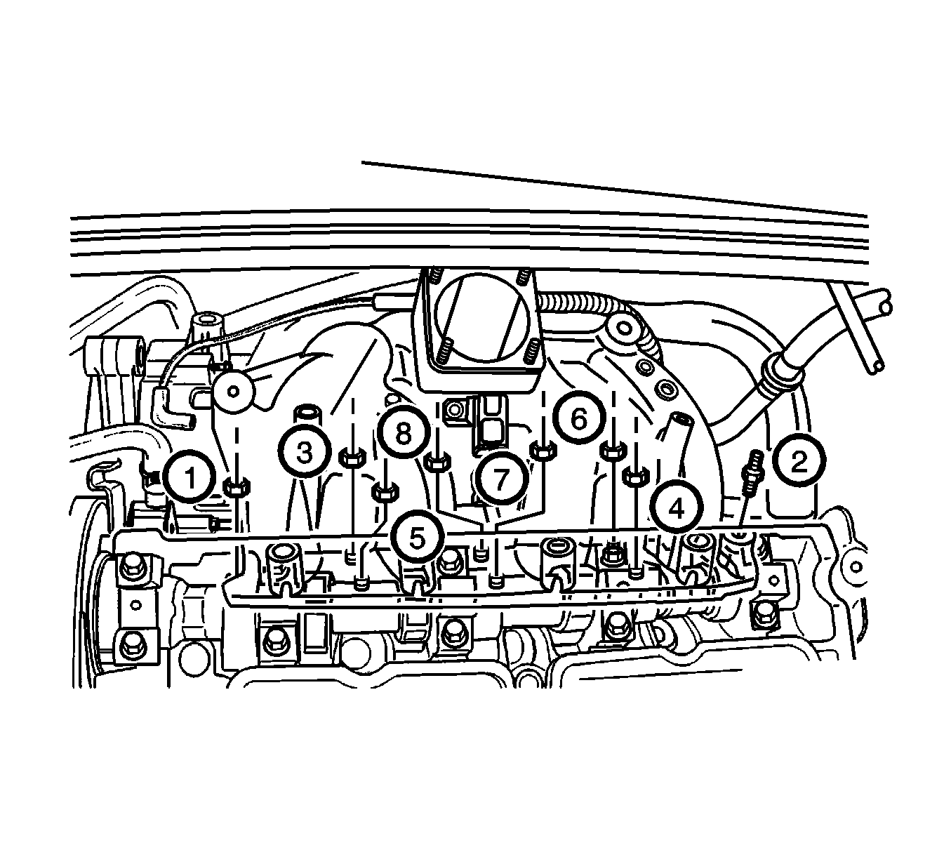
Caution: Refer to Safety Glasses Caution in the Preface section.
Installation Procedure
- Install the intake manifold gasket.
- Install the intake manifold retaining bolt/nuts in the sequence shown.
- Install the valve cover. Refer to Valve Rocker Arm Cover Replacement .
- Install the throttle body assembly. Refer to Throttle Body Assembly Replacement .
- Install the intake manifold support bracket upper bolt to the intake manifold.
- Install the ECM ground terminal bolt from the intake manifold.
- Connect the brake vacuum hose from the intake manifold.
- Install the alternator upper bracket.
- Install the alternator upper bracket bolts.
- Install the EVAP canister purge solenoid bracket bolt and reposition the canister purge solenoid clear of the repair area.
- Install the engine harness wire bracket bolts from the rear of the intake manifold.
- Install the fuel injector rail and fuel injectors as an assembly.
- Connect the vacuum hose at the fuel pressure regulator.
- Connect the throttle cable from the throttle body and the intake manifold.
- Install the air intake tube from the throttle body.
- Connect the breather hose from the valve cover.
- Install the MAT sensor connector.
- Install the air filter housing assembly.
- Install the air filter housing bolts.
- Install the fuel pump fuse.
- Connect the negative battery cable.

Notice: Refer to Fastener Notice in the Preface section.
Tighten
Tighten the manifold bolt/nuts to 18 N·m (13 lb ft).

Tighten
Tighten the support bracket upper bolt to 20 N·m (15 lb ft).

Tighten
Tighten the upper bracket bolt to 35 N·m (26 lb ft).


