Removal Procedure
- Remove the fuel pump fuse.
- Start the engine. After it stalls, crank the engine for 10 seconds to rid the fuel system of fuel pressure.
- Drain the engine coolant. Refer to Cooling System Draining and Filling .
- Disconnect the negative battery cable.
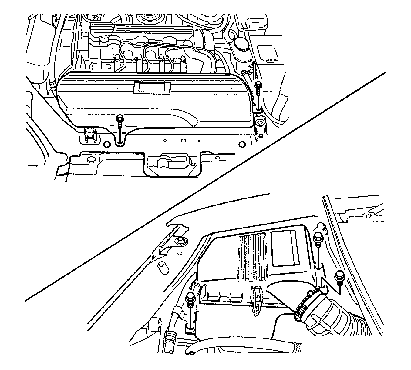
- Remove the air filter housing bolts and the air filter housing assembly.
- Remove the air inlet duct bolts and the air inlet duct.
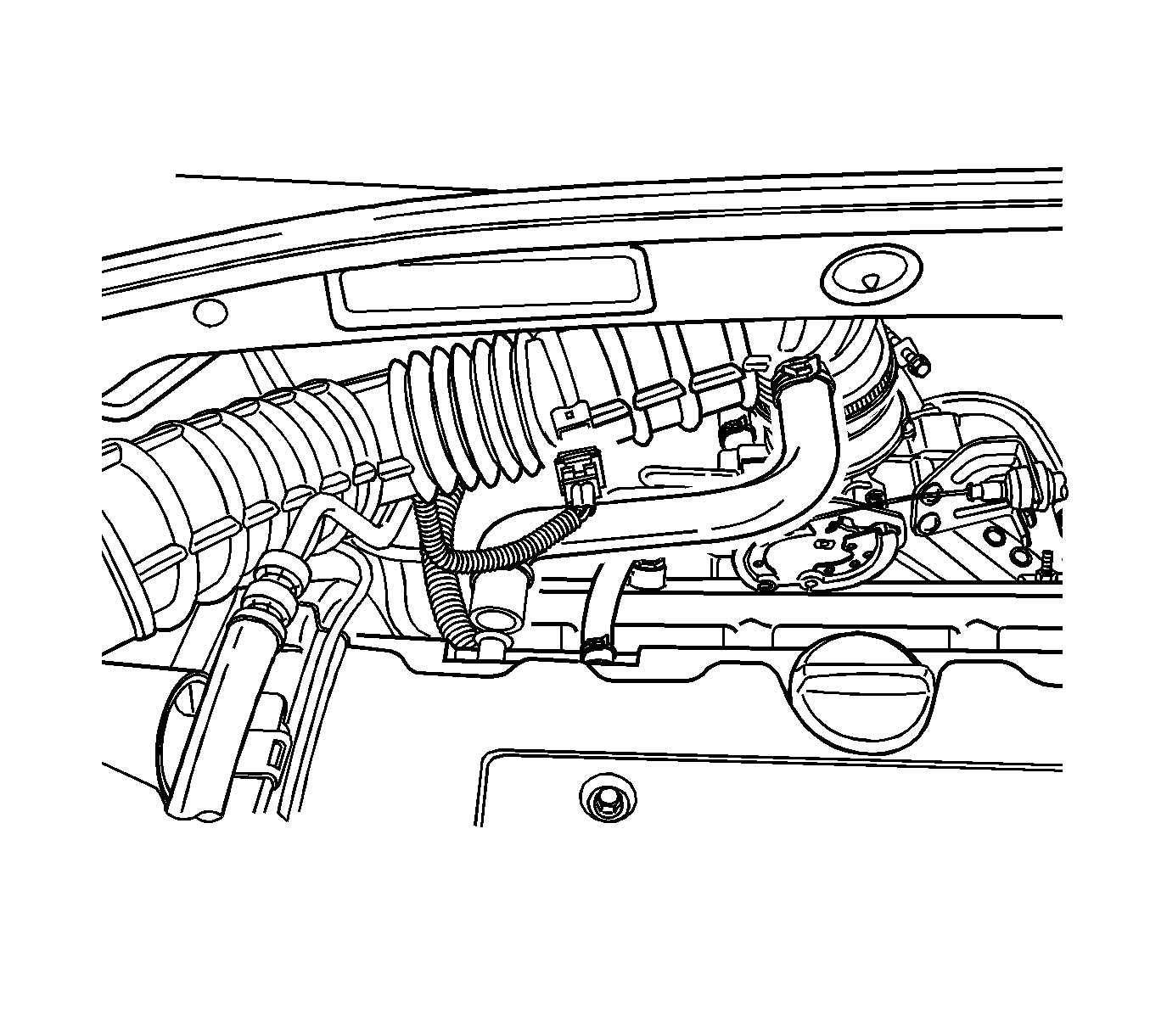
- Disconnect the intake air temperature (IAT) sensor and connector.
- Disconnect the breather tube from the valve cover.
- Remove the air intake tube from the throttle body.
- Disconnect the camshaft position (CMP) sensor connector.
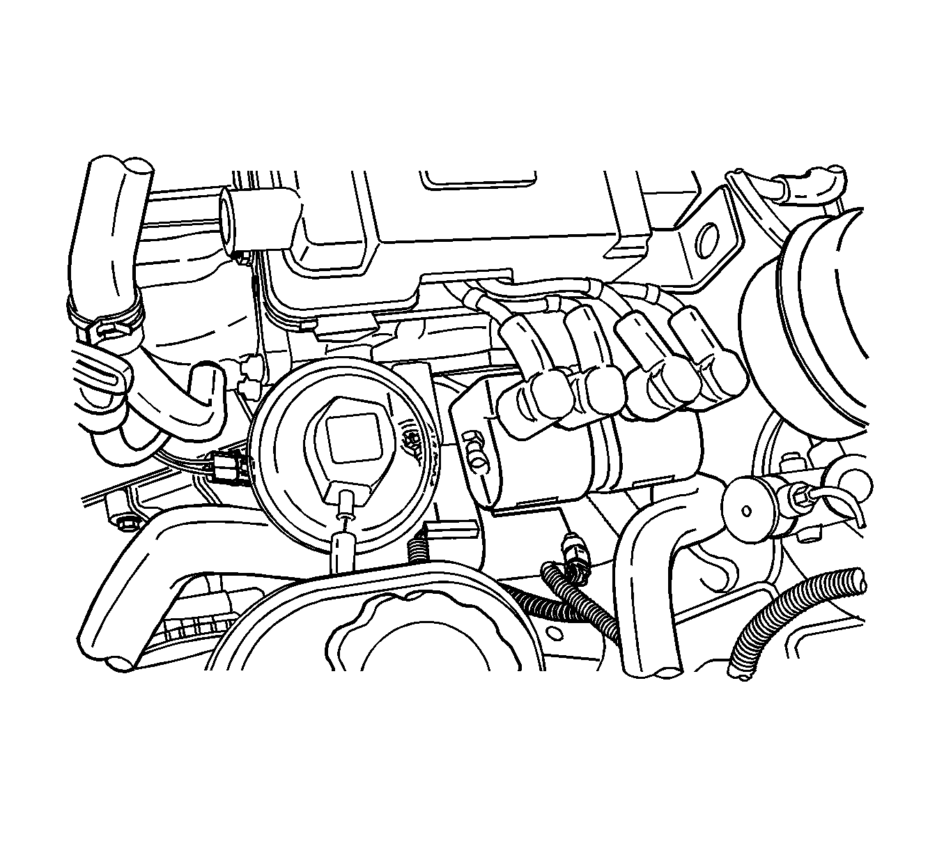
- Disconnect the oxygen sensor connector.
- Disconnect the engine coolant temperature (ECT) sensor connector.
- Disconnect the coolant temperature gage connector.
- Disconnect the exhaust gas recirculation (EGR) valve connector.
- Remove the electronic ignition (EI) system ignition coil.
- Disconnect the heater inlet hose at the cylinder head.
- Remove the coolant pipe bracket bolt.
- Remove the fuel injector rail and fuel injectors as an assembly.
- Remove the generator-to-intake manifold support bracket bolts upper bracket bolts and support bracket.
- Remove the intake manifold-to-generator strap bracket bolt and loosen the bolt on the generator.
- Move the strap clear of the intake manifold.
- Pull out the generator backward.
- Disconnect the coolant hose from the throttle body.
- Disconnect the coolant hose from the cylinder head.
- Disconnect the upper radiator hose at the thermostat housing.
- Remove the forward engine mount. Refer to Engine Mount Replacement .
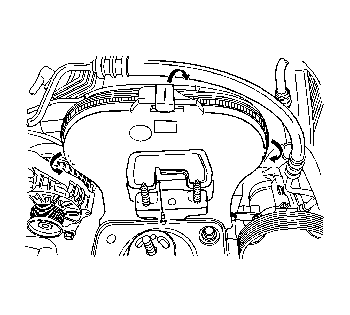
- Disconnect the clips at the upper front timing belt cover.
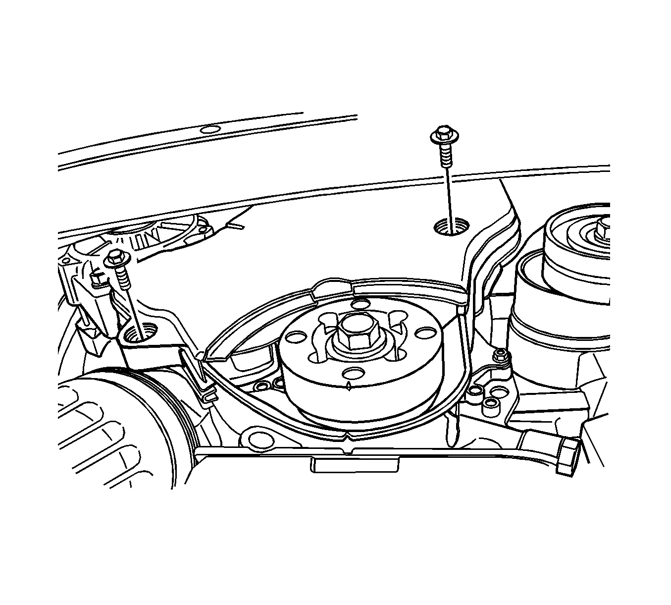
- Remove the torque roll axis cover bolt.
- Remove the torque roll axis cover.
- Remove the right front wheel. Refer to Tire and Wheel Removal and Installation .
- Remove the right front wheel well splash shield.
- Remove the serpentine accessory drive belt. Refer to Power Steering Pump Belt Replacement .
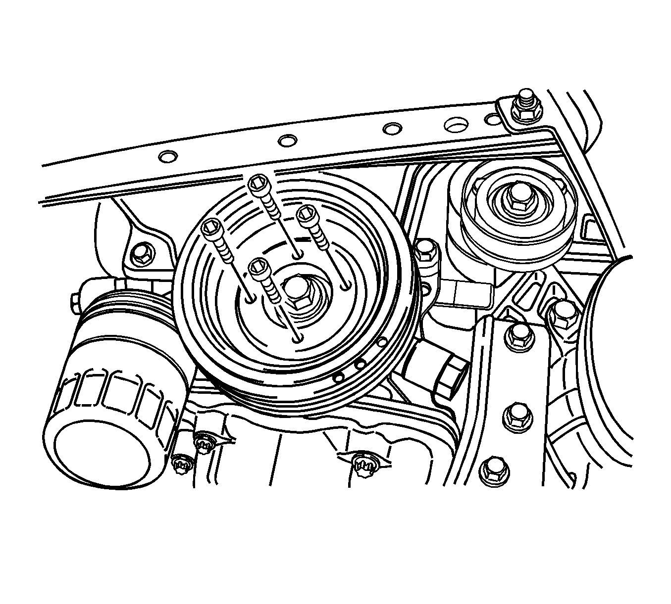
- Remove the crankshaft pulley bolts.
- Remove the crankshaft pulley.
- Remove the front timing belt cover bolts.
- Remove the front timing belt cover.
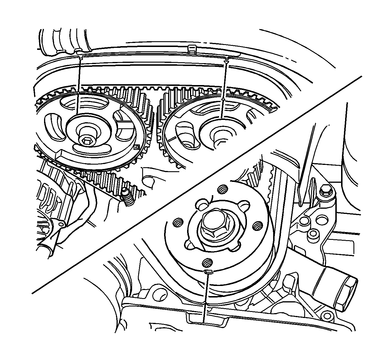
- Using the crankshaft pulley bolt, rotate the crankshaft clockwise until the timing mark on the crankshaft gear is aligned with the notch at the bottom of the rear timing belt cover.
- Remove the timing belt. Refer to Timing Belt Replacement .
- Remove the exhaust manifold heat shield bolts and the exhaust manifold heat shield.
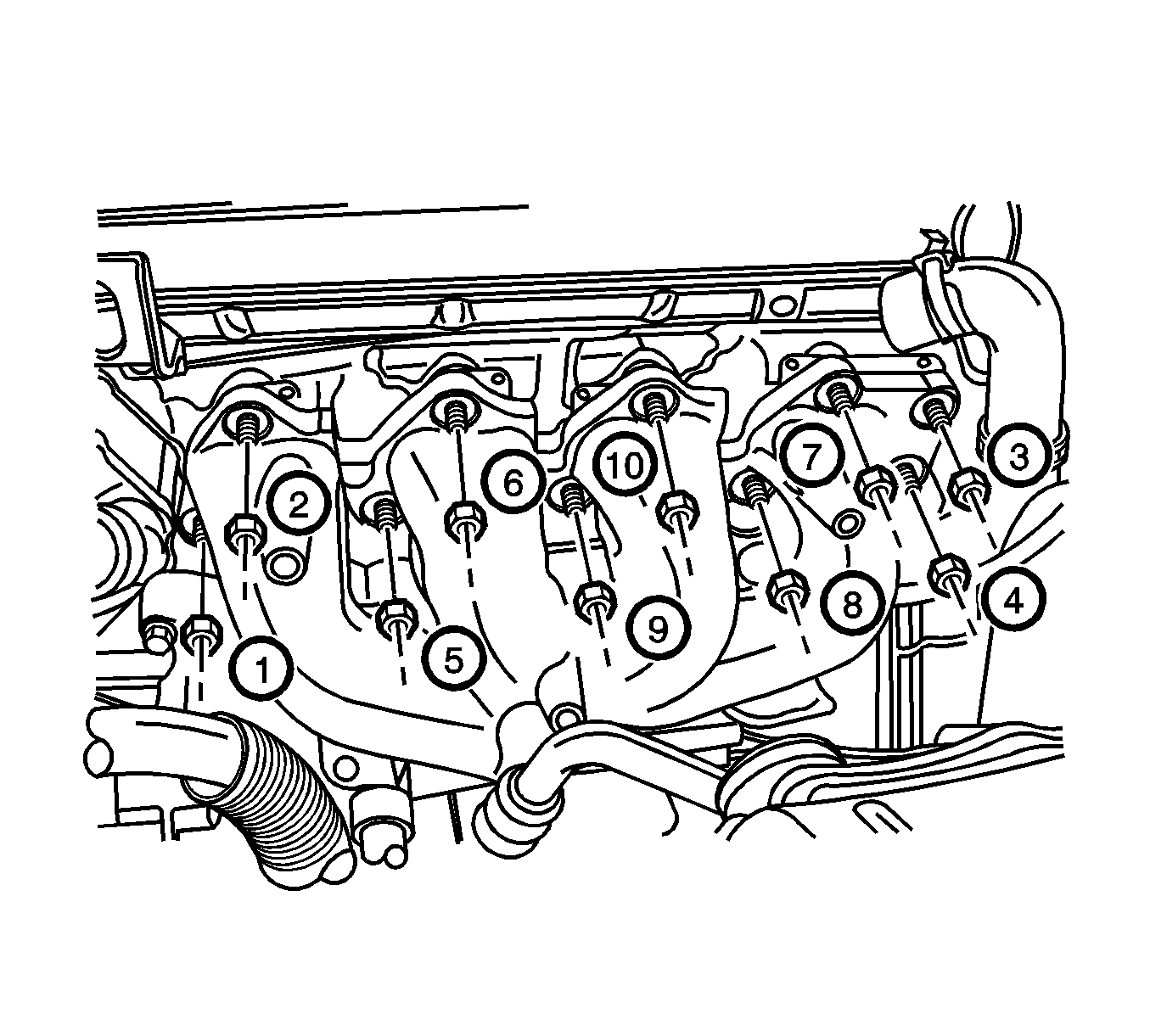
- Remove the exhaust manifold retaining nuts.
- Disconnect the exhaust manifold from the cylinder head.
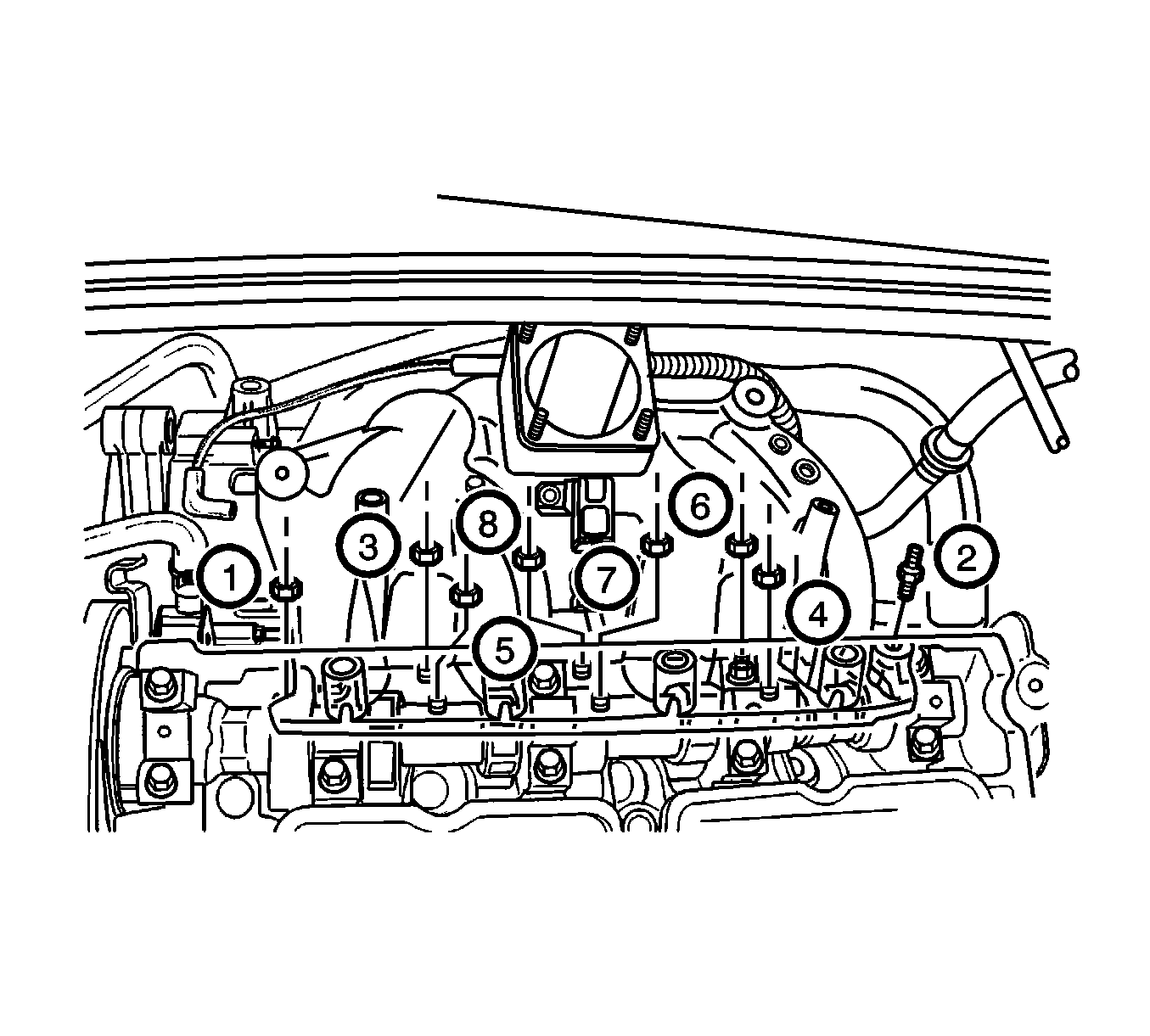
- Remove the intake manifold retaining nut/bolt in the sequence shown.
- Disconnect the intake manifold from the cylinder head.
- Remove the valve cover. Refer to Valve Rocker Arm Cover Replacement .
- While holding the intake camshaft firmly in place, remove the intake camshaft gear bolt.
- Remove the intake camshaft gear.
- While holding the exhaust camshaft firmly in place, remove the exhaust camshaft gear bolt.
- Remove the exhaust camshaft gear.
- Remove the camshaft bearing cap bolts gradually for each camshaft bearing cap.
- Remove the intake/exhaust camshaft caps. Maintain the correct positions for installation.
- Remove the intake/exhaust camshaft.
- Loosen all of the cylinder head bolts gradually and in the sequence shown.
- Remove the cylinder head bolts.
- Remove the cylinder head and cylinder head gasket.
Caution: Refer to Safety Glasses Caution in the Preface section.
Caution: Refer to Relieving Fuel Pressure Caution in the Preface section.
Caution: Refer to Battery Disconnect Caution in the Preface section.
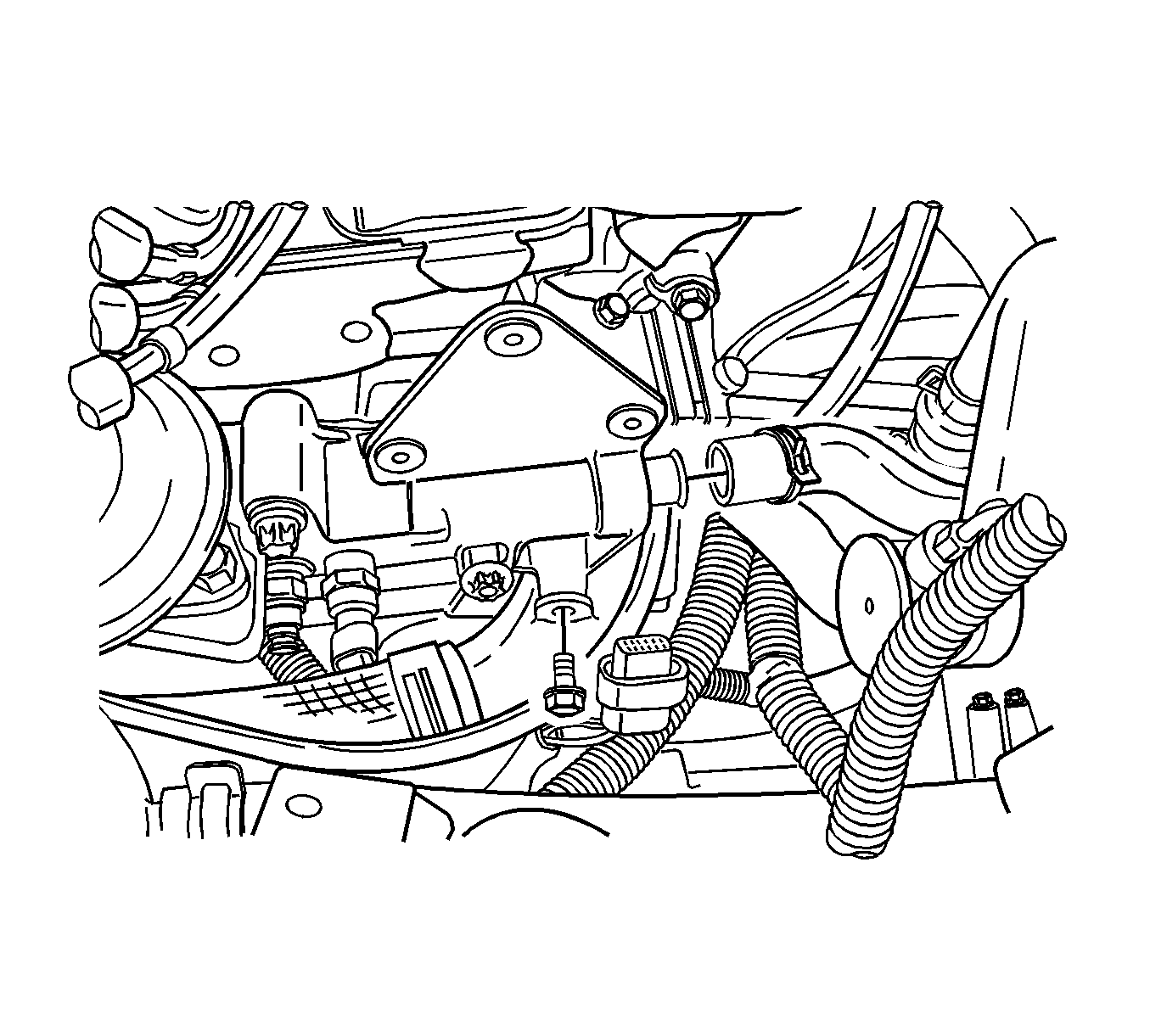
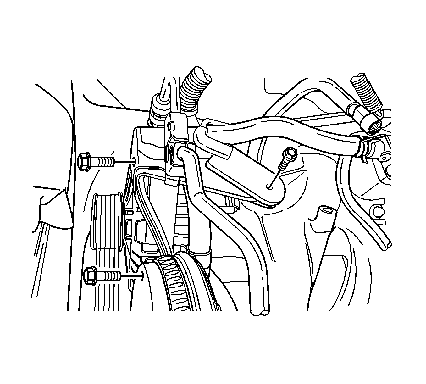
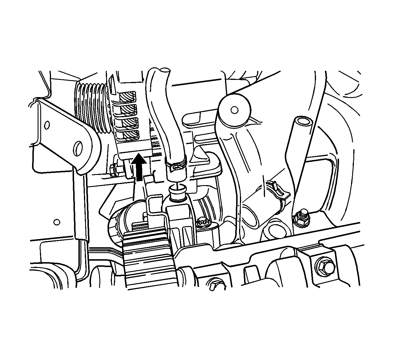
Loosen the generator lower bracket-to-generator bolt.
Notice: Refer to Belt Dressing Notice in the Preface section.
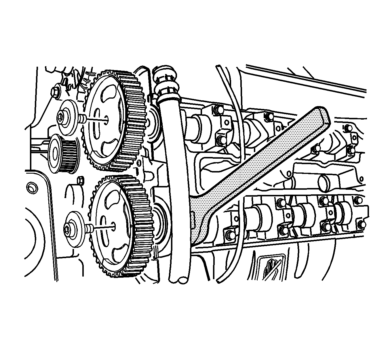
Notice: Use extreme care when removing the camshaft not to nick, scratch, or damage the camshaft lobes or bearing surfaces.
Notice: All camshaft journals are the same diameter, so care must be used in removing or installing the camshaft to avoid damage to the camshaft bearings.
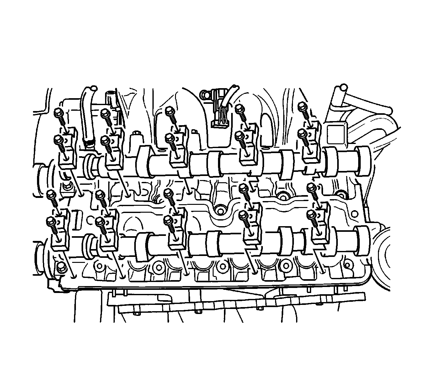
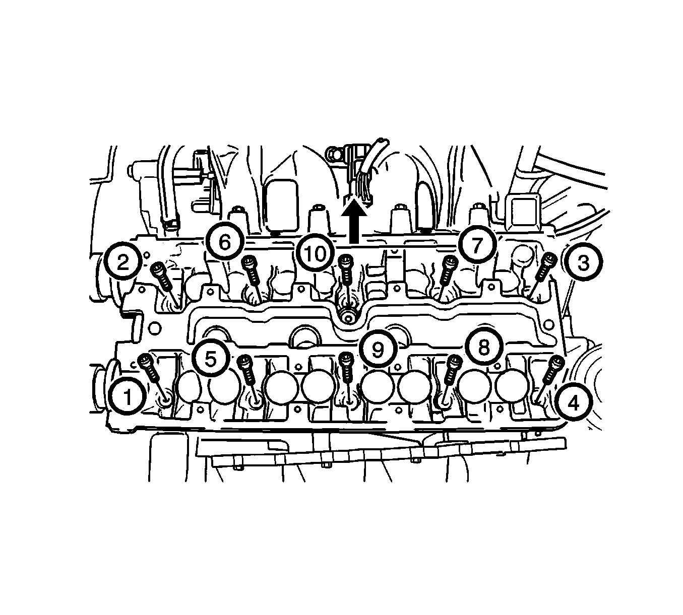
Notice: Use extreme care when removing the cylinder head to prevent any engine oil , dirt, or coolant from entering the engine. Damage to the engine could result.
Installation Procedure
- Clean and Inspect the cylinder head and sealing surface of the engine block. Refer to Cylinder Head Cleaning and Inspection .
- Install the cylinder head and the cylinder head gasket.
- Install the cylinder head bolts
- Install the intake/exhaust camshaft.
- Install the intake/exhaust camshaft caps. Maintain the correct positions for installation.
- Install the camshaft bearing cap bolts gradually and in the sequence shown for each camshaft bearing cap.
- Install the exhaust camshaft gear.
- While holding the exhaust camshaft firmly in place, install the exhaust camshaft gear bolt.
- Install the intake camshaft gear.
- While holding the intake camshaft firmly in place, reinstall the intake camshaft gear bolt.
- Install the valve cover. Refer to Valve Rocker Arm Cover Replacement .
- Connect the intake manifold to the cylinder head.
- Install the intake manifold retaining nuts/bolt.
- Install the exhaust manifold to the cylinder head.
- Install the exhaust manifold retaining nuts. Tighten the exhaust manifold nuts in the following sequence: 9, 10, 6, 5, 8, 7, 2, 1, 3, 4.
- Install the exhaust manifold heat shield bolts and the exhaust manifold heat shield.
- Install the timing belt. Refer to Timing Belt Replacement .
- Using the crankshaft pulley bolt, rotate the crankshaft clockwise until the timing mark on the crankshaft gear is aligned with the notch at the bottom of the rear timing belt cover.
- Install the front timing belt cover.
- Install the front timing belt cover bolts.
- Install the crankshaft pulley.
- Install the crankshaft pulley bolts.
- Install the serpentine accessory drive belt. refer to Power Steering Pump Belt Replacement .
- Install the right front wheel well splash shield.
- Install the right front wheel. Refer to Tire and Wheel Removal and Installation .
- Install the torque roll axis cover.
- Install the torque roll axis cover bolt.
- Install the clips at the upper front timing belt cover.
- Install the forward engine mount. Refer to Engine Mount Replacement .
- Install the upper radiator hose at the thermostat housing.
- Install the coolant hose from the cylinder head.
- Install the coolant hose from the throttle body.
- Push in the generator backward.
- Loosen the generator lower bracket-to-generator bolt.
- Move the strap clear of the intake manifold.
- Install the intake manifold-to-generator strap bracket bolt and tighten the bolt on the generator.
- Install the generator-to-intake manifold support bracket bolts upper bracket bolts and support bracket.
- Install the fuel injector rail and the fuel injectors as an assembly.
- Install the coolant pipe bracket bolt.
- Install the heater inlet hose at the cylinder head.
- Install the EI system ignition coil.
- Connect the EGR valve connector.
- Connect the coolant temperature gage connector.
- Connect the ECT sensor connector.
- Connect the oxygen sensor connector.
- Connect the CMP sensor connector.
- Install the air intake tube from the throttle body.
- Install the breather hose to the valve cover.
- Connect the IAT sensor connector.
- Install the air inlet duct bolts and the air inlet duct.
- Install the air filter housing bolts and the air filter housing assembly.
- Connect the negative battery cable.
- Fill the engine coolant. Refer to Cooling System Draining and Filling .
- Install the fuel pump fuse.
- Start the engine and inspect for leaks.

Notice: Refer to Fastener Notice in the Preface section.
Tighten
Tighten the cylinder head bolts in the sequence shown to 25 N·m (18 lb ft) + 90 degrees + 90 degrees + 90 degrees.

Tighten
Tighten the camshaft bearing cap bolts to 8 N·m (71 lb in).
Tighten
Tighten the camshaft gear bolt to 50 N·m (37 lb in) + 60 degrees + 15 degrees.

Tighten
Tighten the camshaft gear bolt to 50 N·m (37 lb ft) + 60 degrees + 15 degrees.

Tighten
Tighten the intake manifold nuts/bolts to 18 N·m (13 lb ft).

Tighten
| • | Tighten the exhaust manifold nuts in the first stage to 13 N·m (10 lb ft). |
| • | Tighten the exhaust manifold nuts in the second stage to 13 N·m (10 lb ft). |
| • | Tighten the exhaust manifold nuts in the third stage to 15 N·m (11 lb ft). |
| • | Tighten the exhaust manifold nuts in the fourth stage to 15 N·m (11 lb ft). |
Tighten
Tighten the exhaust manifold heat shield bolts to 15 N·m (11 lb ft).


Tighten
Tighten the front cover bolts to 6 N·m (53 lb ft).

Tighten
Tighten the crankshaft pulley bolts to 20 N·m (15 lb ft).

Tighten
Tighten the axis cover bolts to 6 N·m (53 lb in).


Tighten
Tighten the bolt to 20 N·m (15 lb ft).
Tighten
Tighten the bolts to 20 N·m (15 lb ft).


Tighten
Tighten the air duct bolts to 8 N·m (71 lb in).
