Tools Required
| • | J 22888-20A Bearing Puller with J 22888-35
Puller Legs |
Disassembly Procedure
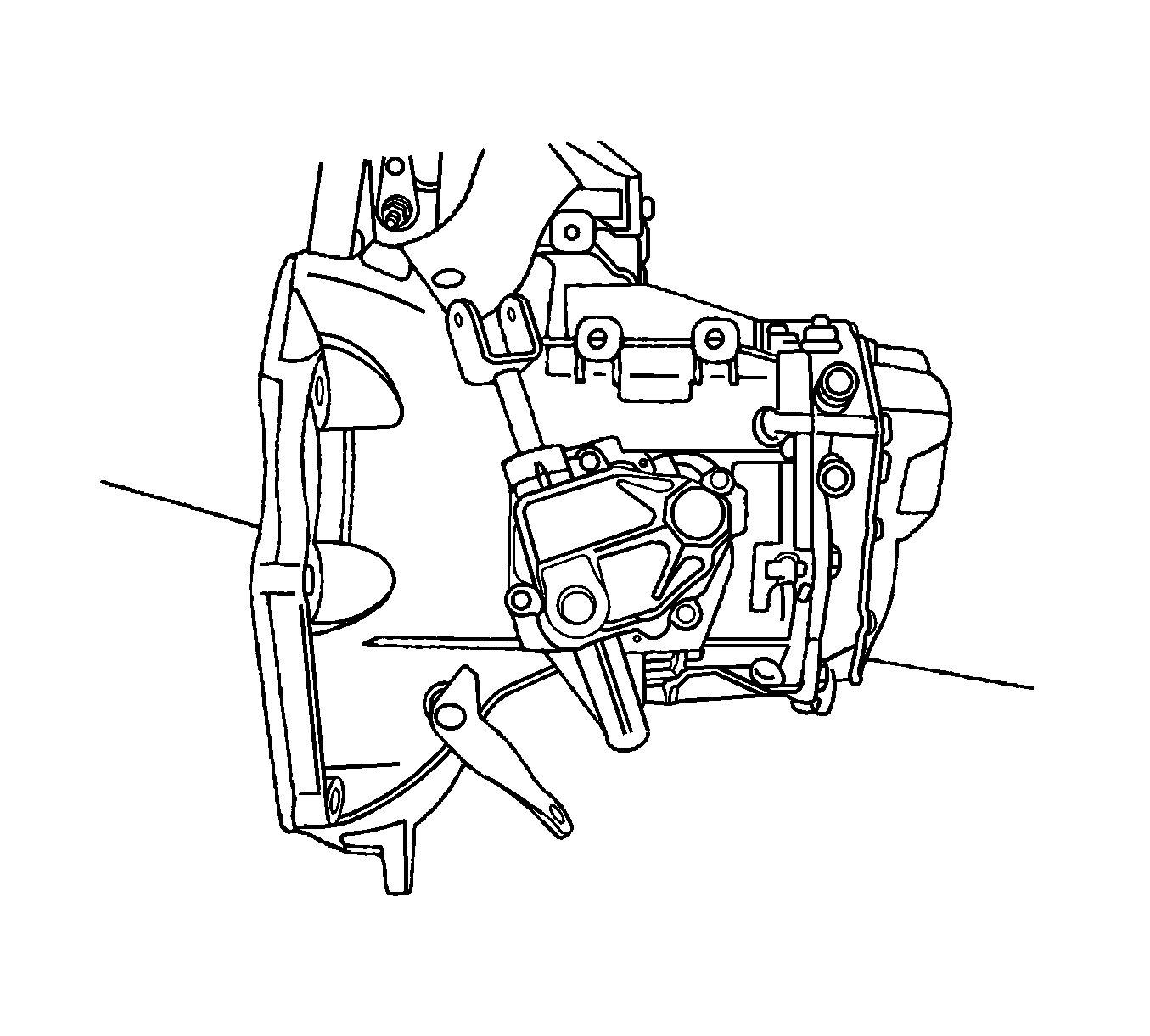
- Remove the transaxle from the vehicle. Refer to
Transmission Replacement
.
- Remove the filler plug at the cover.
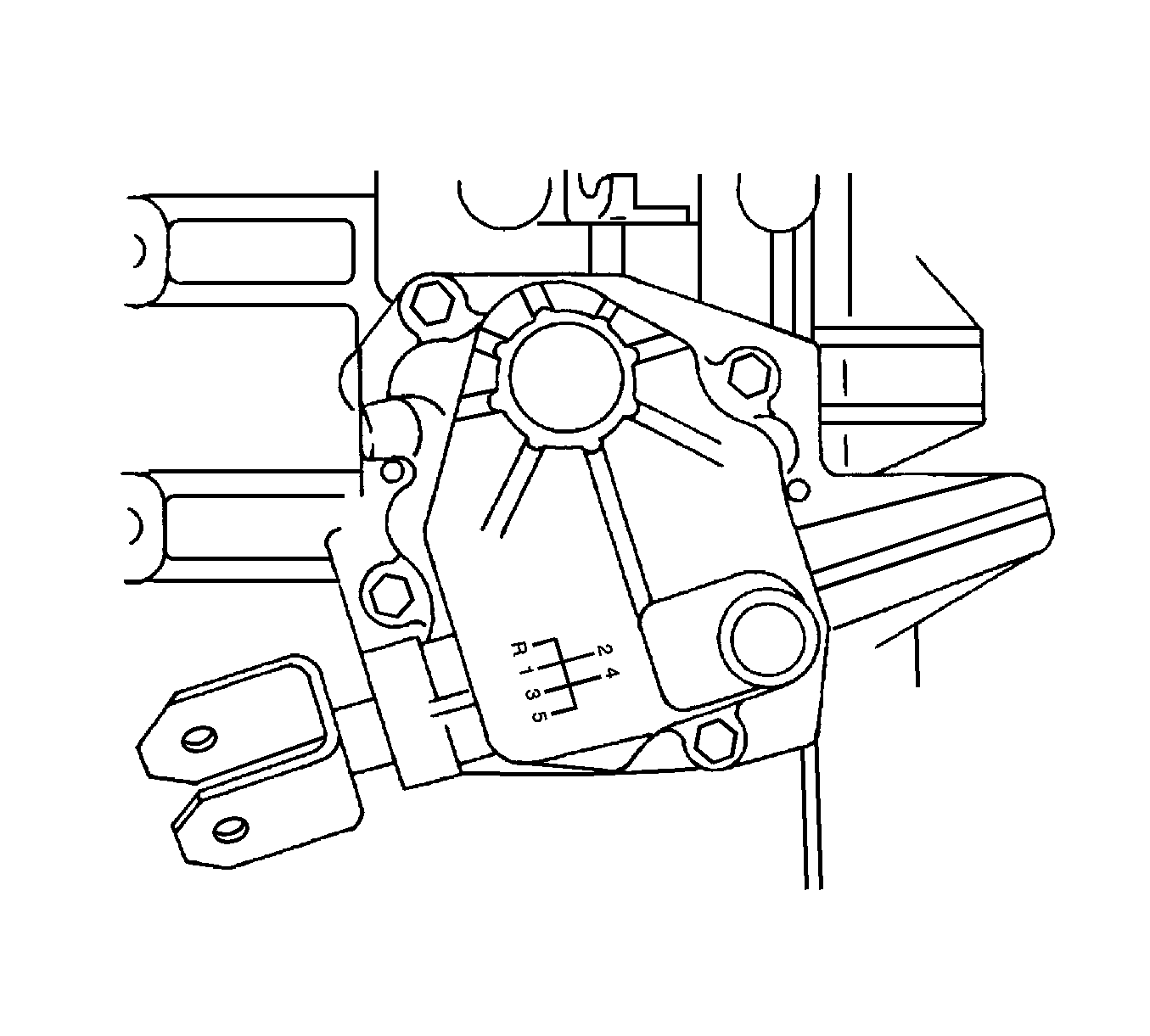
- Remove the bolts from the gearshift lever cover.
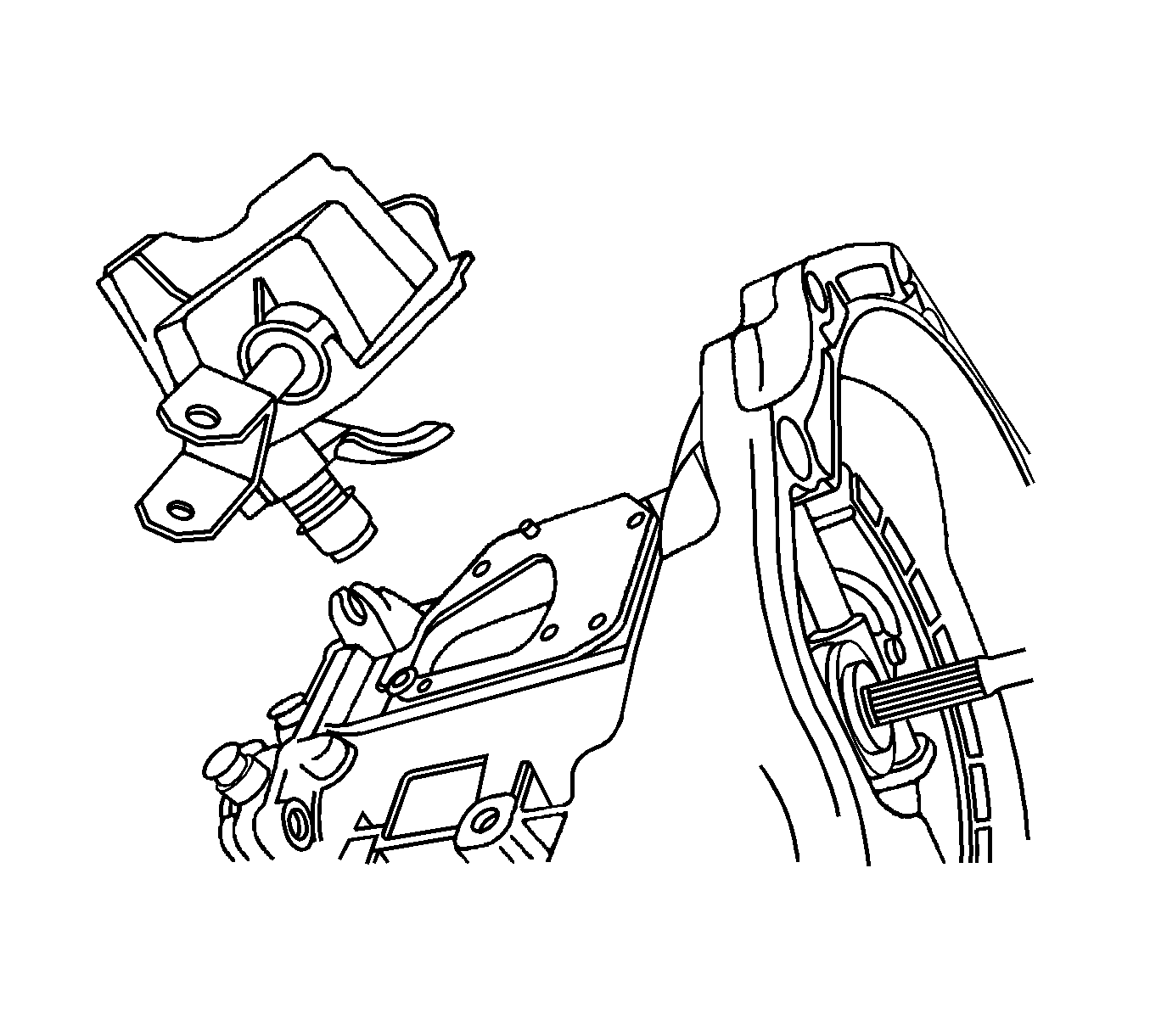
- Remove the gearshift lever cover.
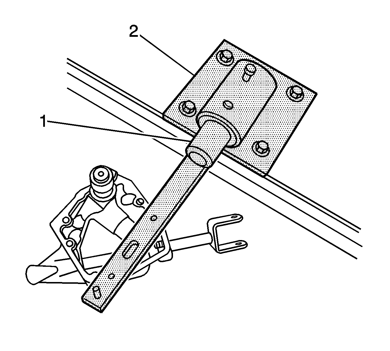
- Bolt the gearshift lever cover to the KM-552
(1).
- Position the KM-552
into the J 3289-20
(2).
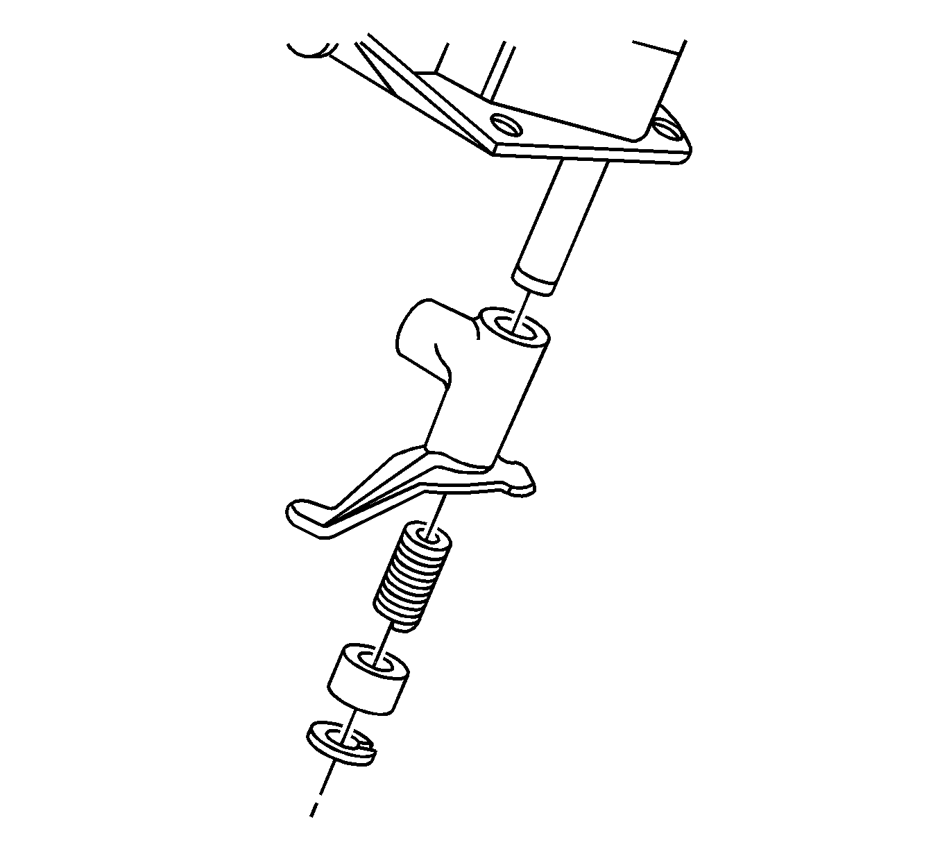
- Remove the snap ring, the bushing, the spring, and
the intermediate lever.
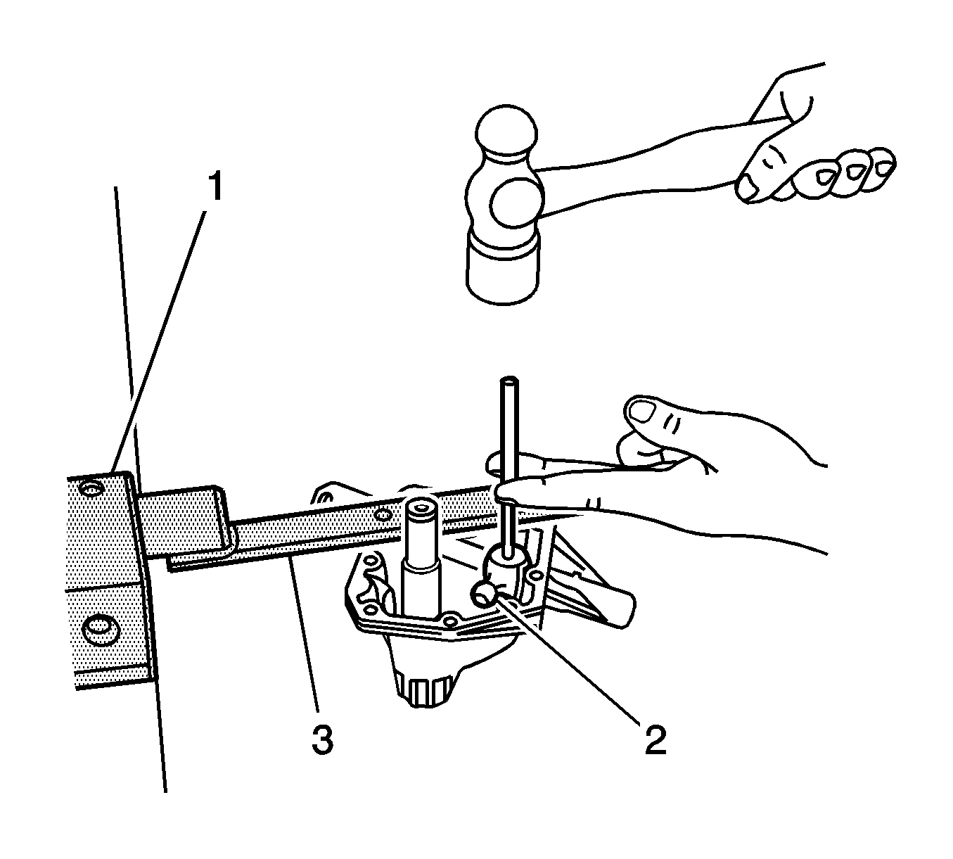
- Using the J 3289-20
(1)
and the KM-522
(2), remove the shift
finger lever pin.
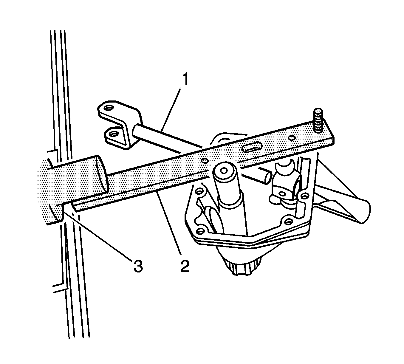
- Using the KM-522
(2),
remove the gearshift rod and the shift finger lever.
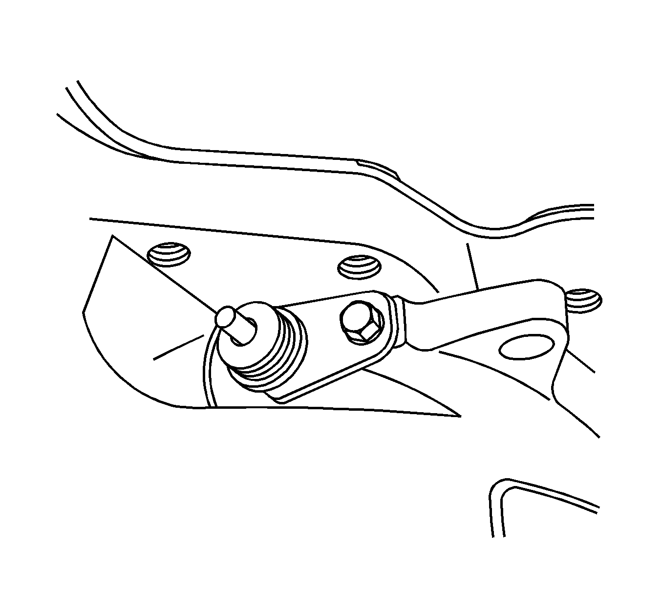
- Remove the bolt and the speedometer-driven gear from
the transaxle housing.
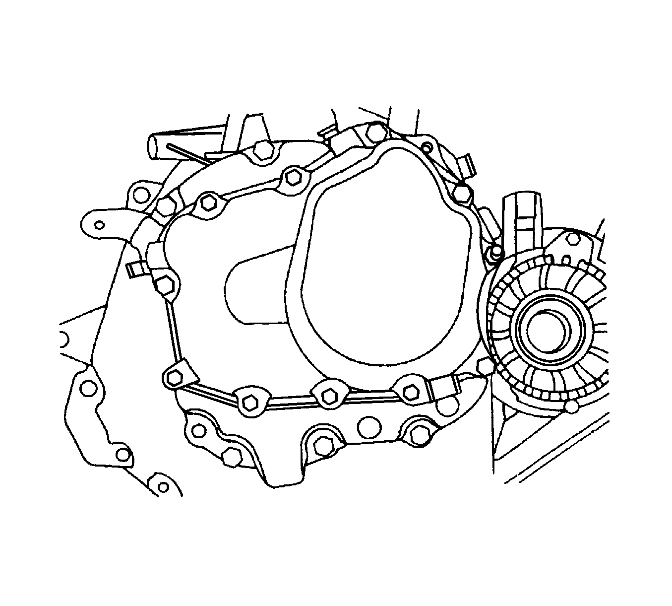
- Remove the transaxle cover bolts.
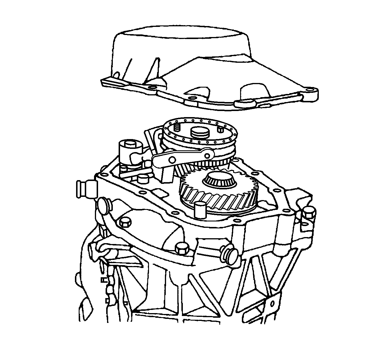
- Remove the transaxle cover.
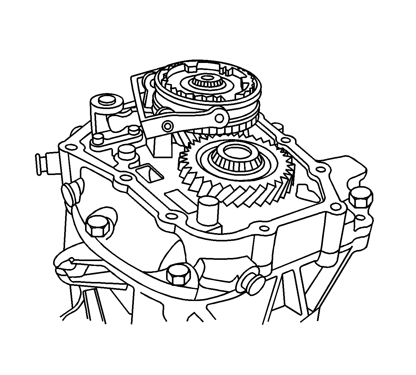
- Shift the transaxle into 2nd gear.
- Remove the bearing plate bolts.
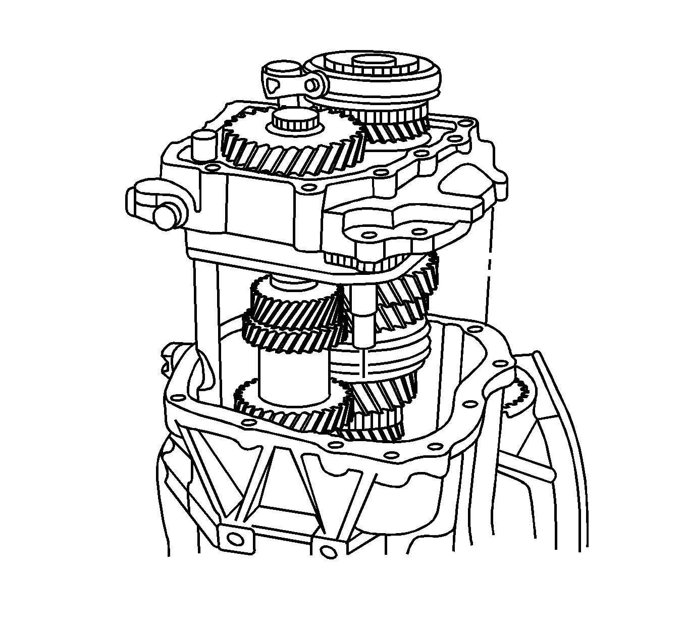
- Remove the bearing plate from the case with the shafts
attached.
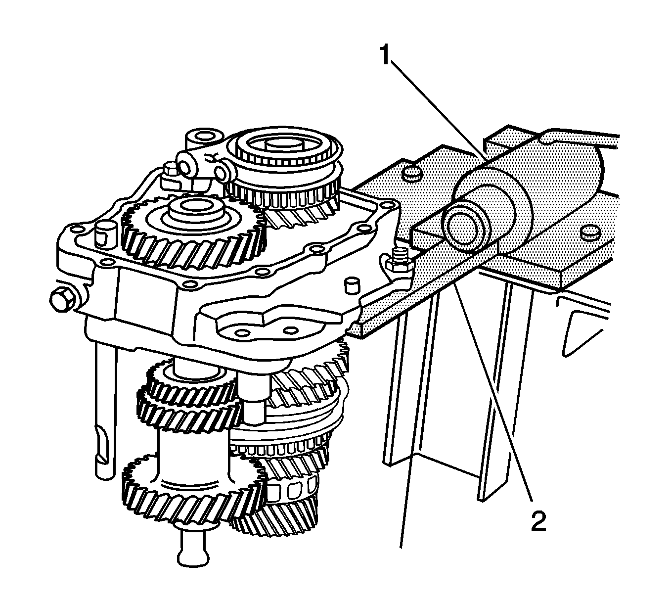
- Shift the transaxle into reverse (R).
- Bolt the bearing plate to the KM-552
(2)
and install the KM-552
(2) into
the J 3289-20
(1).
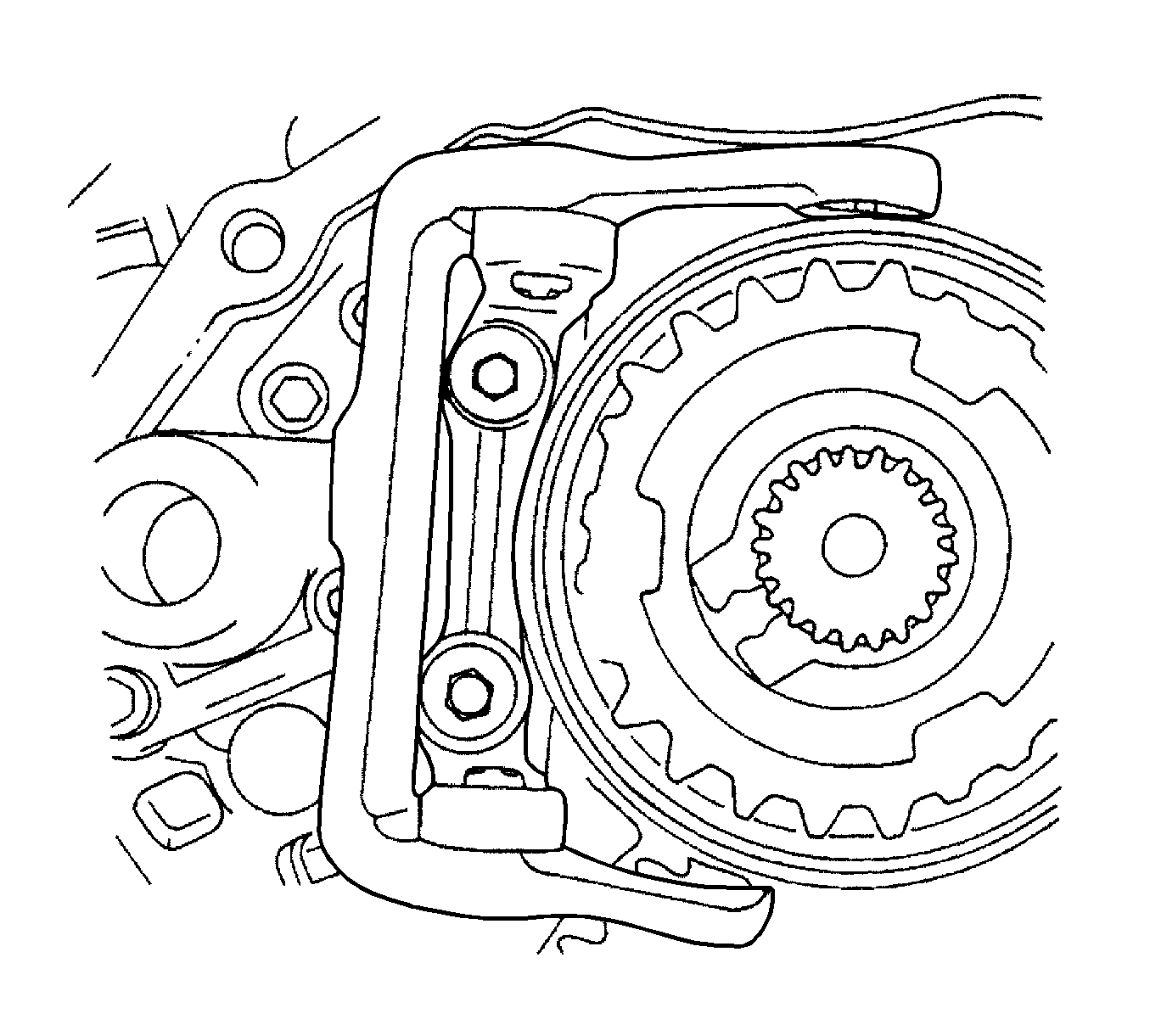
- Remove the bolts and the 5th gear fork from
the bearing plate.
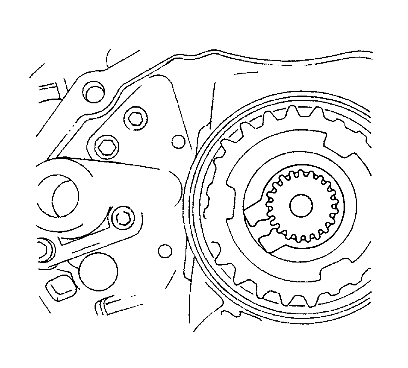
- Remove the mainshaft-driven 5th speed assembly
snap ring.
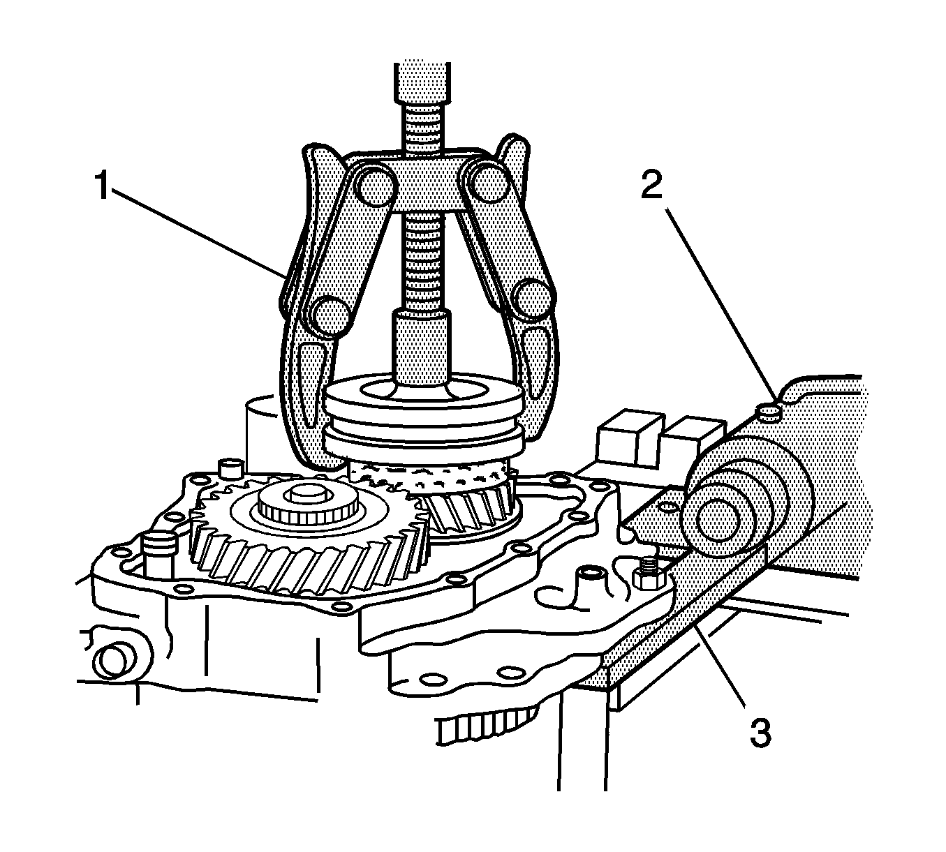
- Remove the 5th driven gear synchronizer sleeve
and the synchronizer gear using the J 22888-20A
(1)
with the puller legs J 22888-35.
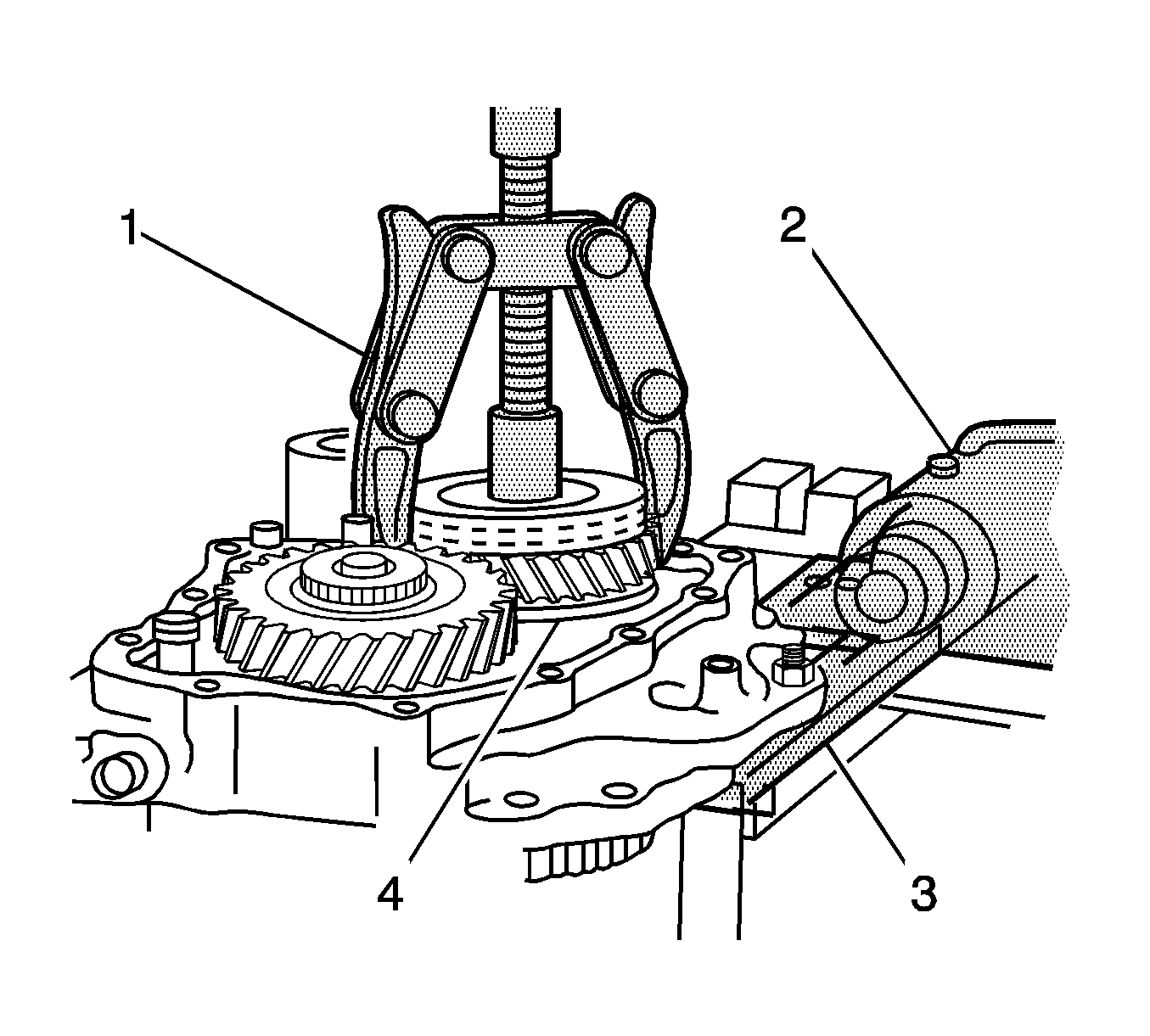
- Using the J 22888-20A
(1)
and the J 22888-35
, remove the mainshaft-driven
5th gear assembly (4).
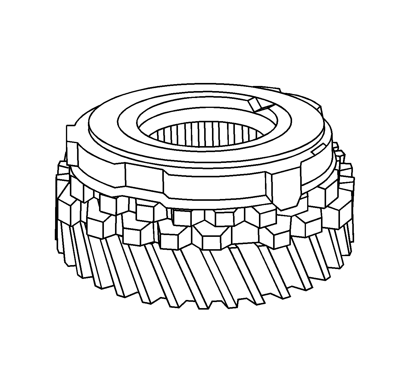
- Remove the brass synchronizer ring.
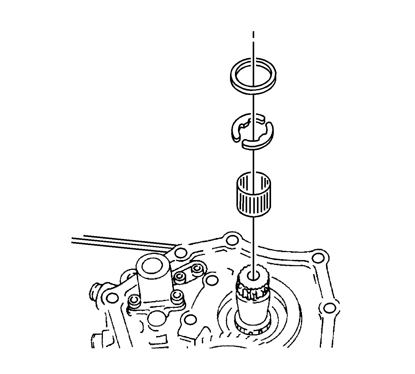
- Remove the needle bearing, the retaining ring, and
the thrust washers.
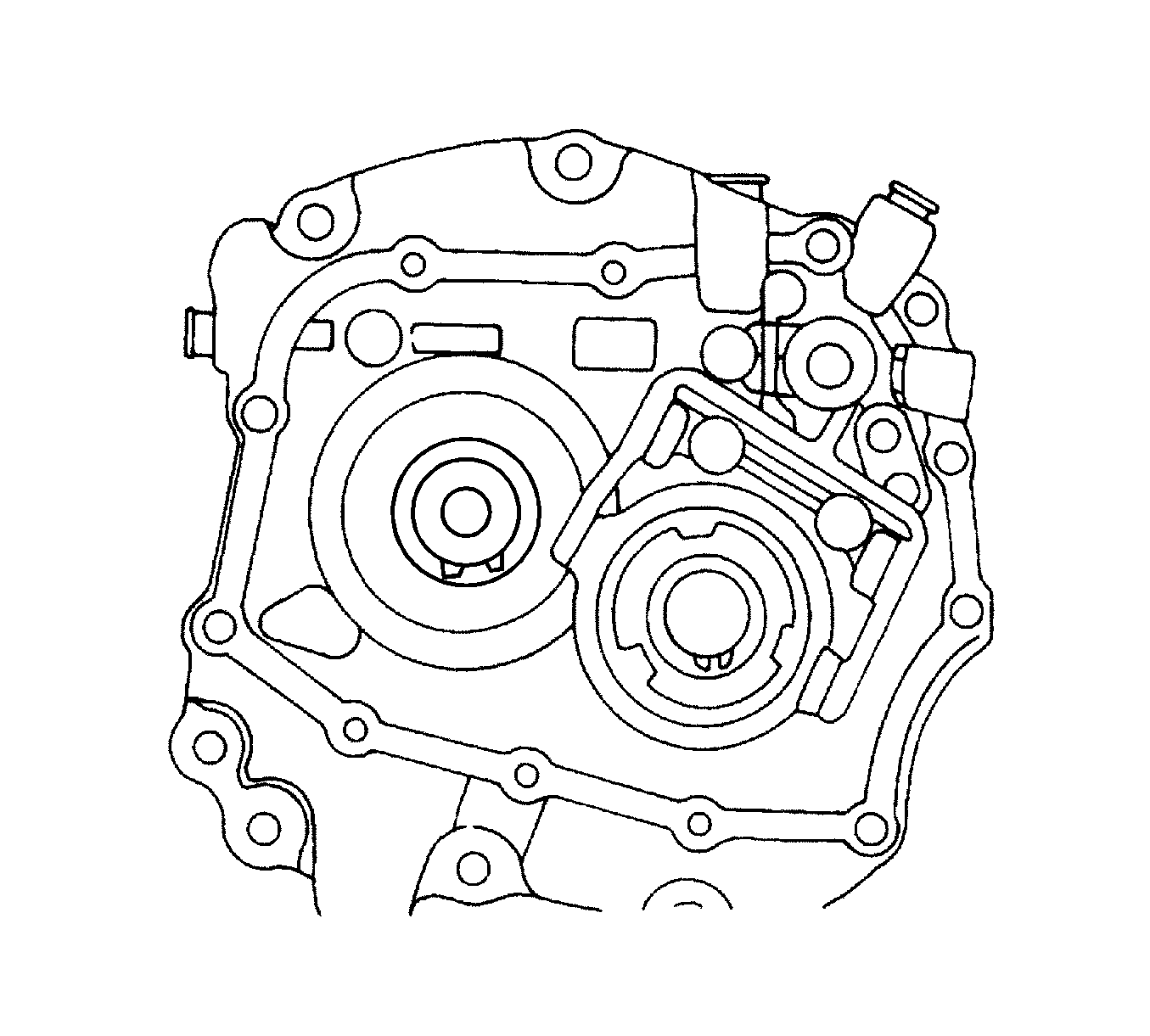
- Remove the input drive 5th gear snap ring.
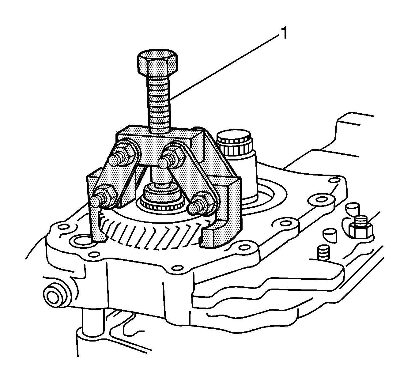
- Remove the input drive 5th gear using the KM-553-A
(1).
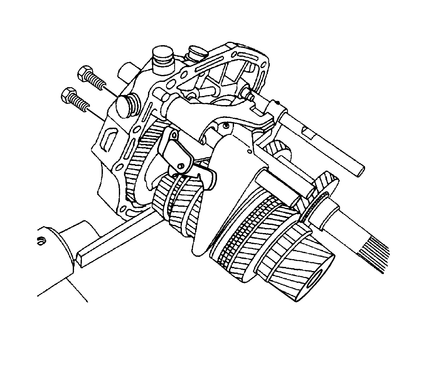
- Remove the bolts and the 5th gearshift connector
from the bearing plate using the pawl.
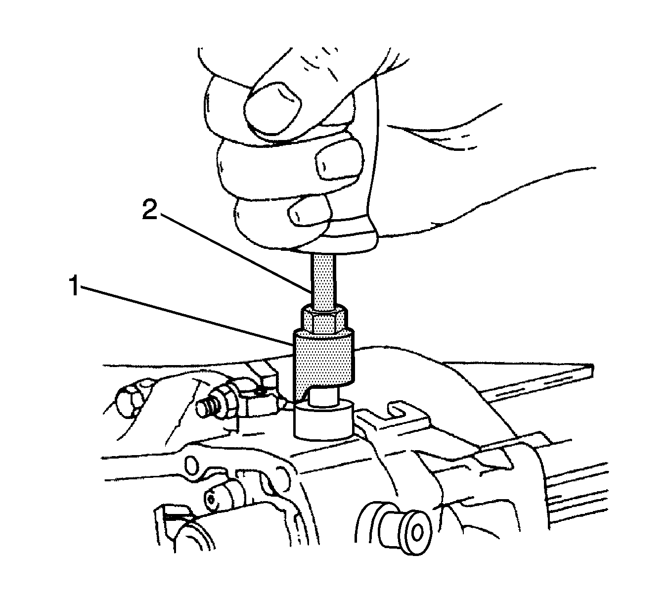
- Remove the 4 shift-rod plugs using the J 42469
(1) and the J 6125-B
(2).
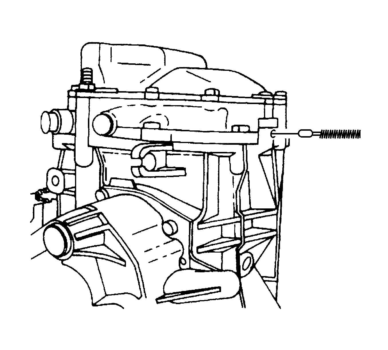
- Remove the spring and the rod lock pin from the small
plug hole.
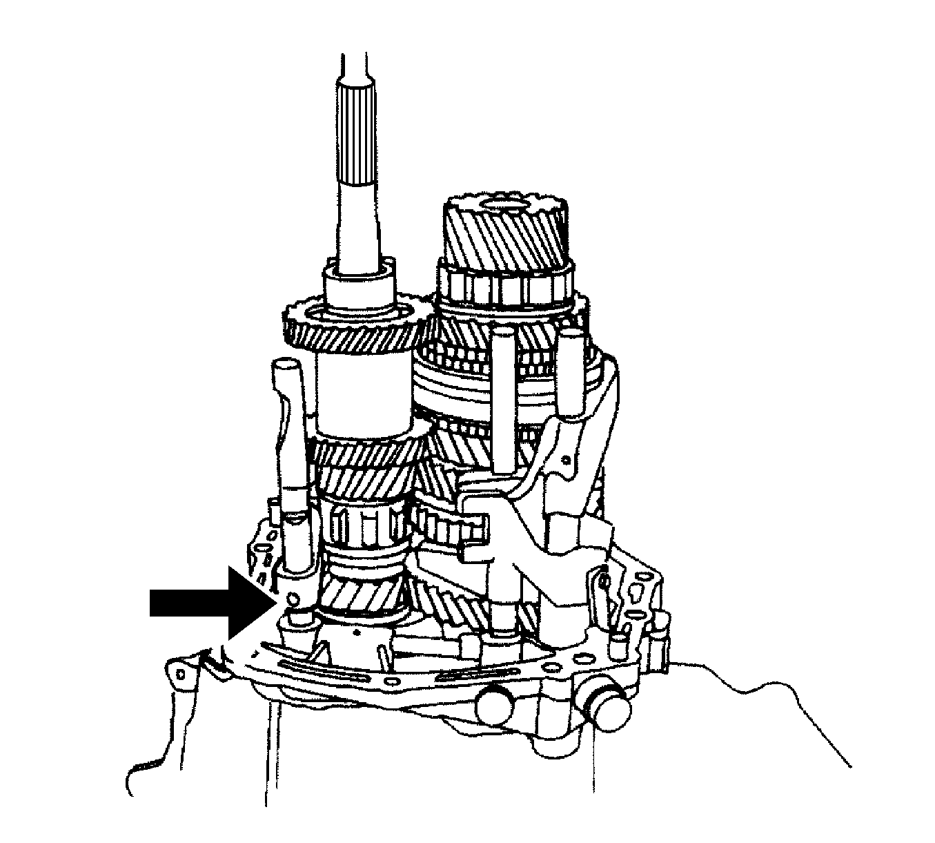
- Remove the pin from the reverse gearshift rod/fork
assembly.
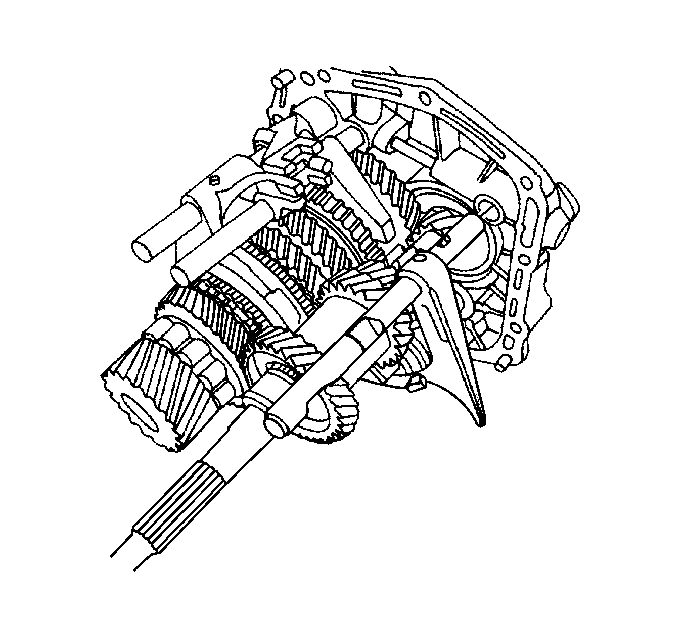
- Remove the reverse gearshift rod/fork assembly from
the bearing plate.
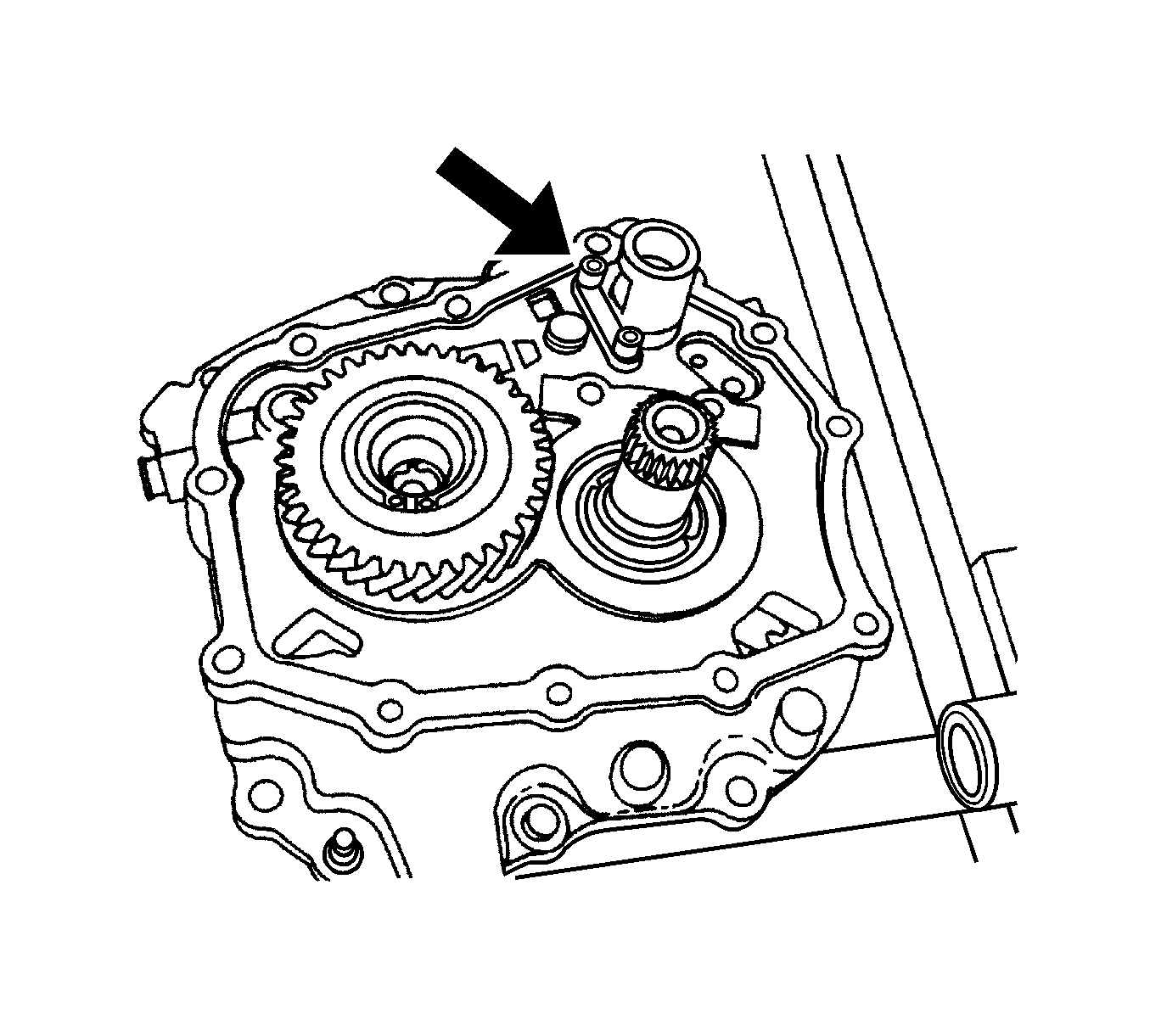
- Using the KM-525
,
remove the bolts from the support bracket.
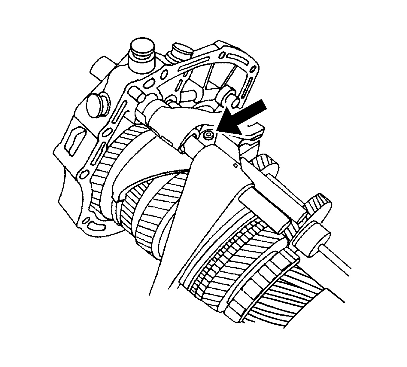
- Remove the 1st-2nd gearshift fork holding pin.
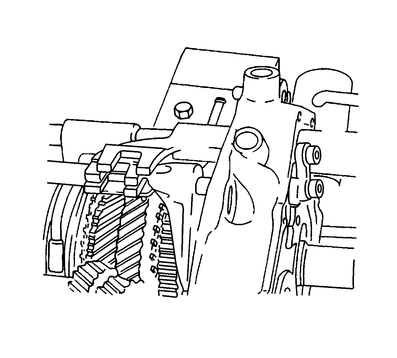
- Drive the 1st-2nd gearshift rod out until it is just
free of the bearing plate.
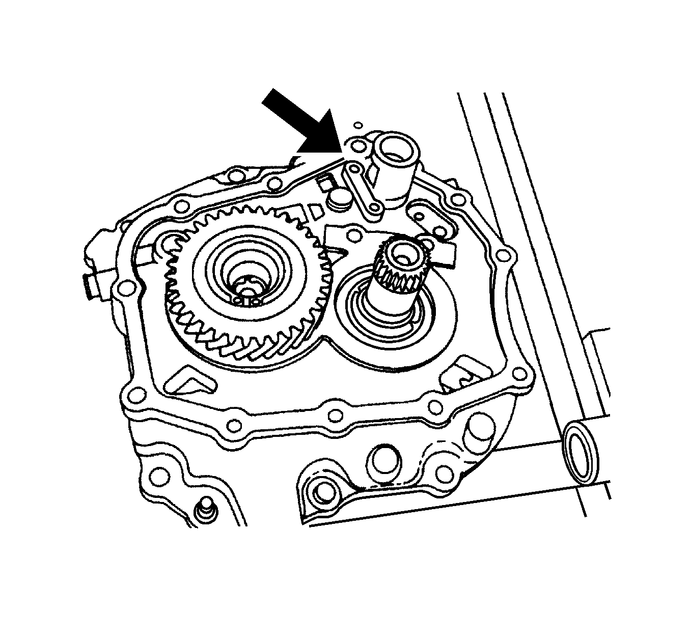
- Remove the support bracket from the bearing plate.
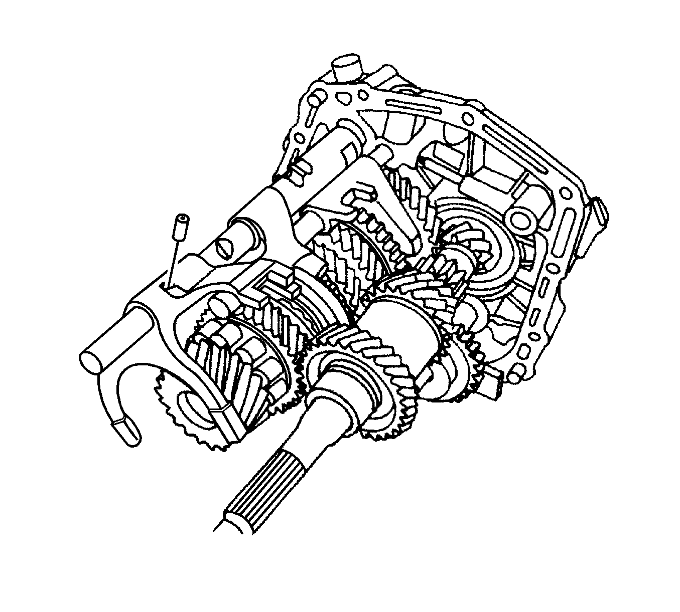
- Remove the 3rd-4th gearshift fork holding pin and
the 3rd-4th gearshift rod.
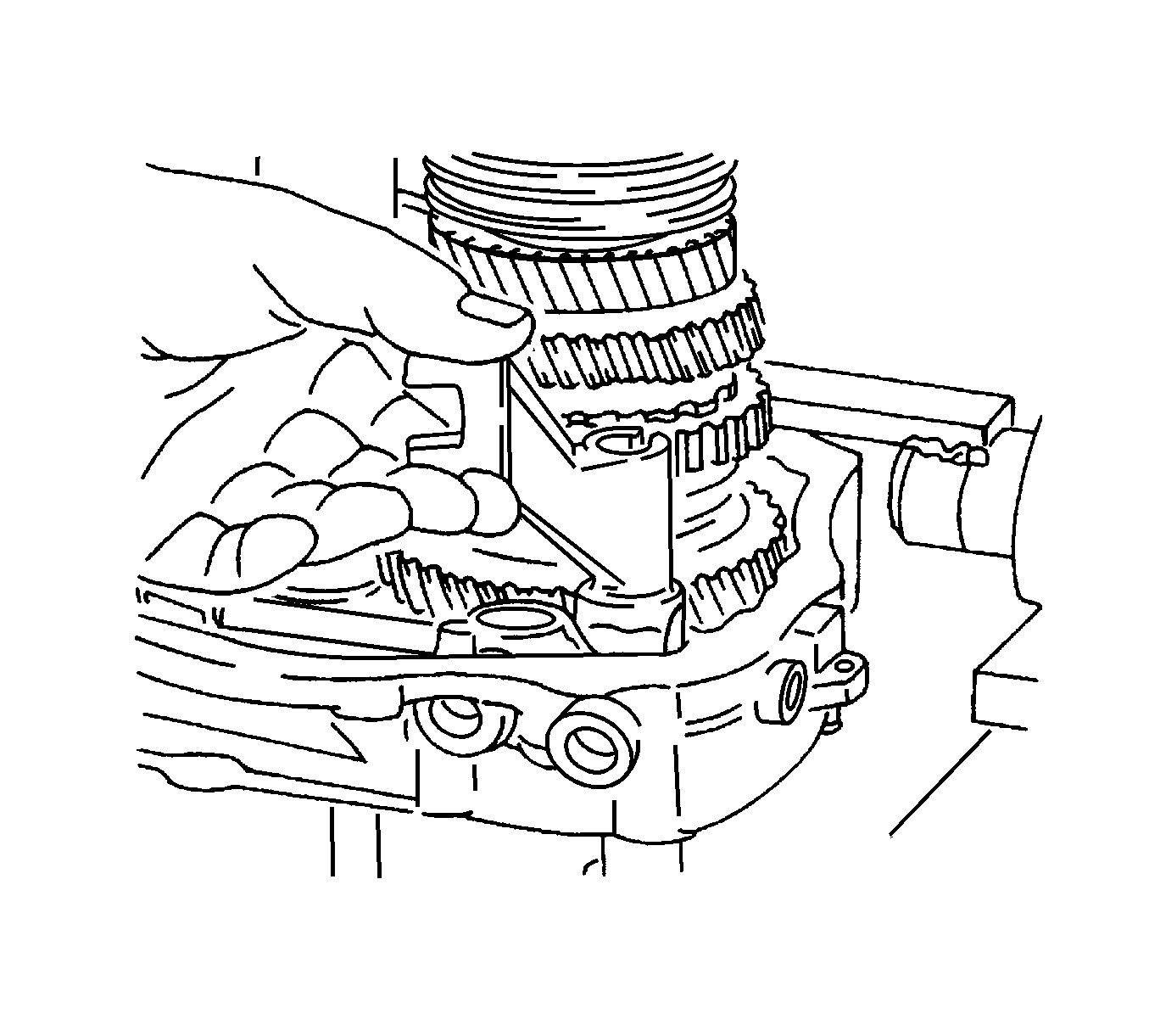
- Remove the 5th gearshift lever from the bearing
plate.
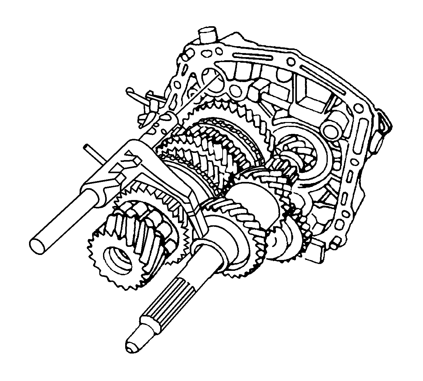
- Remove the 1st-2nd gearshift rod.
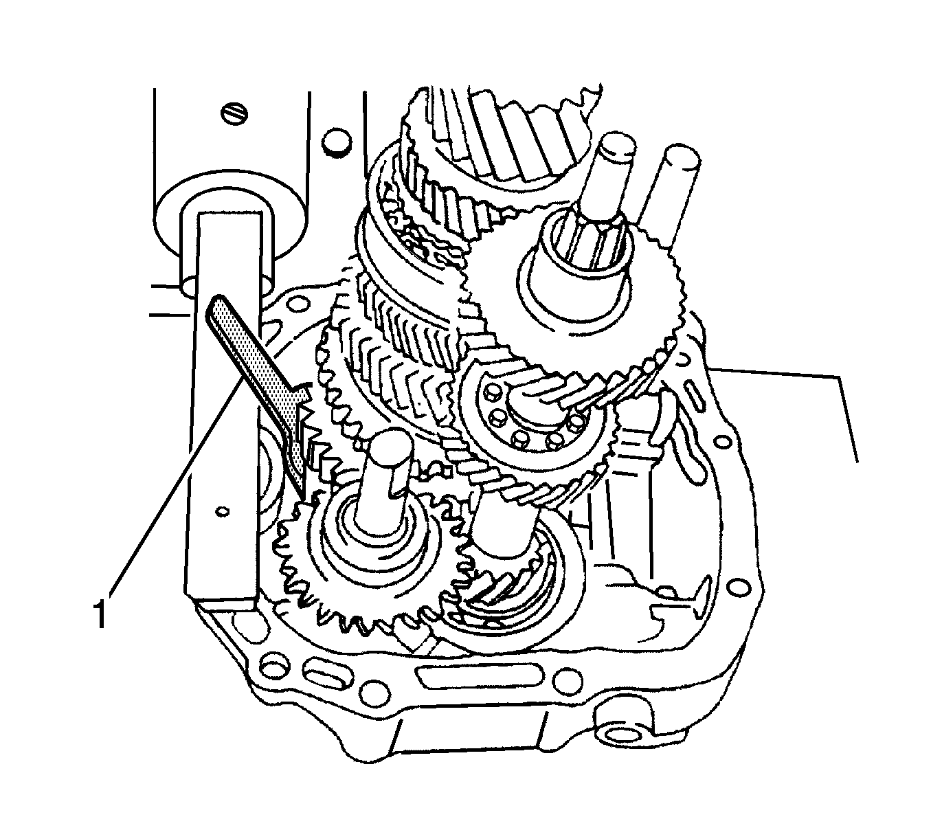
- Compress the snap ring holding the mainshaft and secure
it with the J 36633
(1).
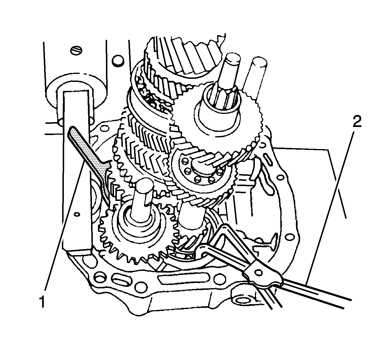
- Hold the snap ring open at the base of the input shaft
using the snap ring pliers (2).
- Remove the mainshaft assembly and the input shaft assembly from the bearing
plate.


