Tools Required
J 39580 Power Pack Stand Engine and Transaxle Assembly Support Remover/Installer
Removal Procedure
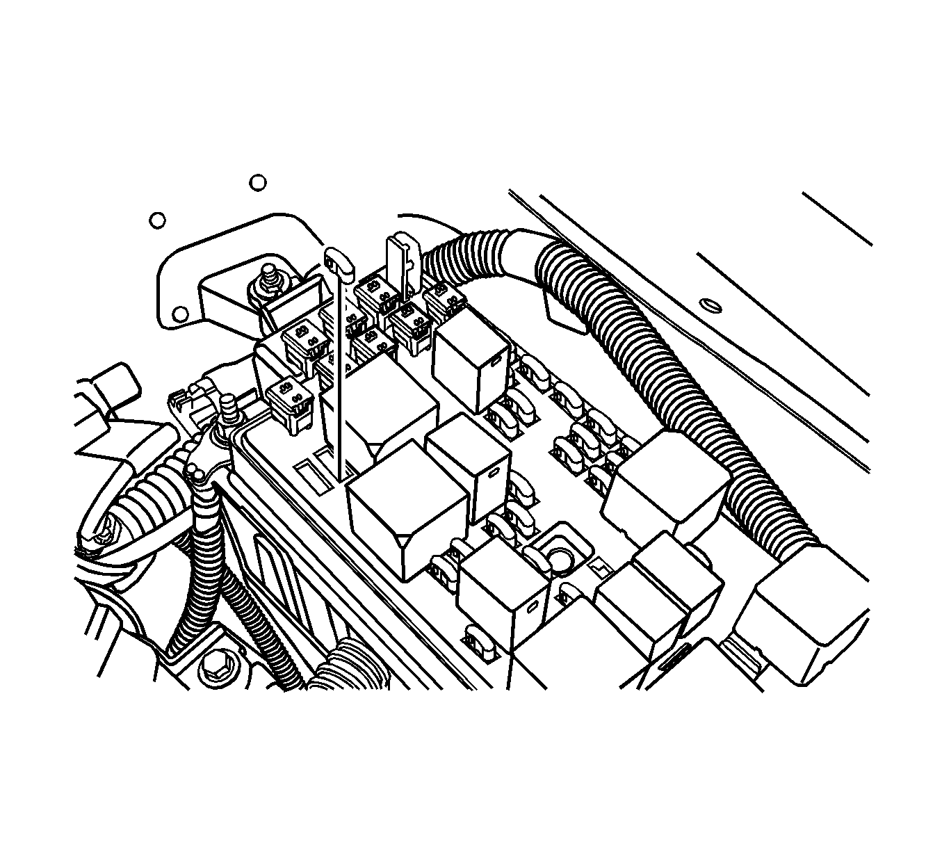
- Remove the fuel pump fuse.
- Start the engine. After it stalls, crank the engine for 10 seconds to rid the fuel system of fuel pressure.
- Remove the air filter bolts and the air filter assembly.
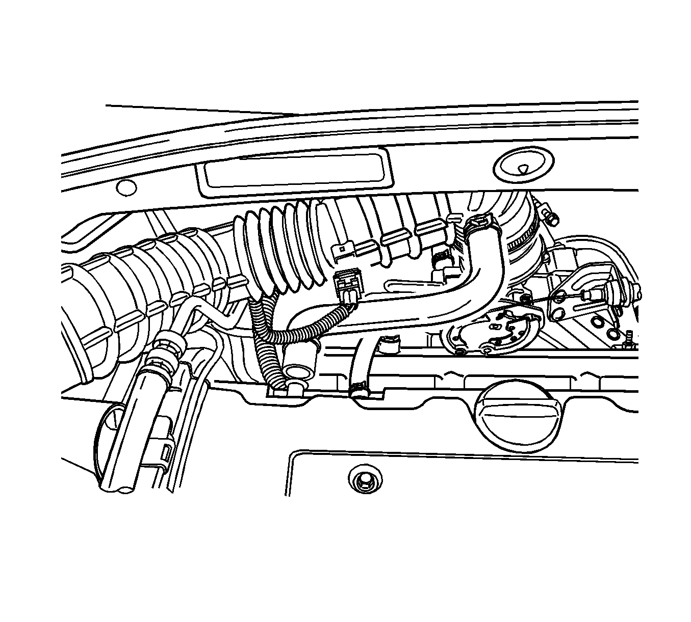
- Remove the air inlet duct bolts and the air inlet duct.
- Disconnect the manifold intake temperature sensor connector.
- Disconnect the breather hose from the valve cover.
- Disconnect the air intake tube from the throttle body.
- Drain the engine coolant. Refer to Cooling System Draining and Filling .
- Discharge the air conditioning system, if equipped. Refer to Refrigerant Recovery and Recharging .
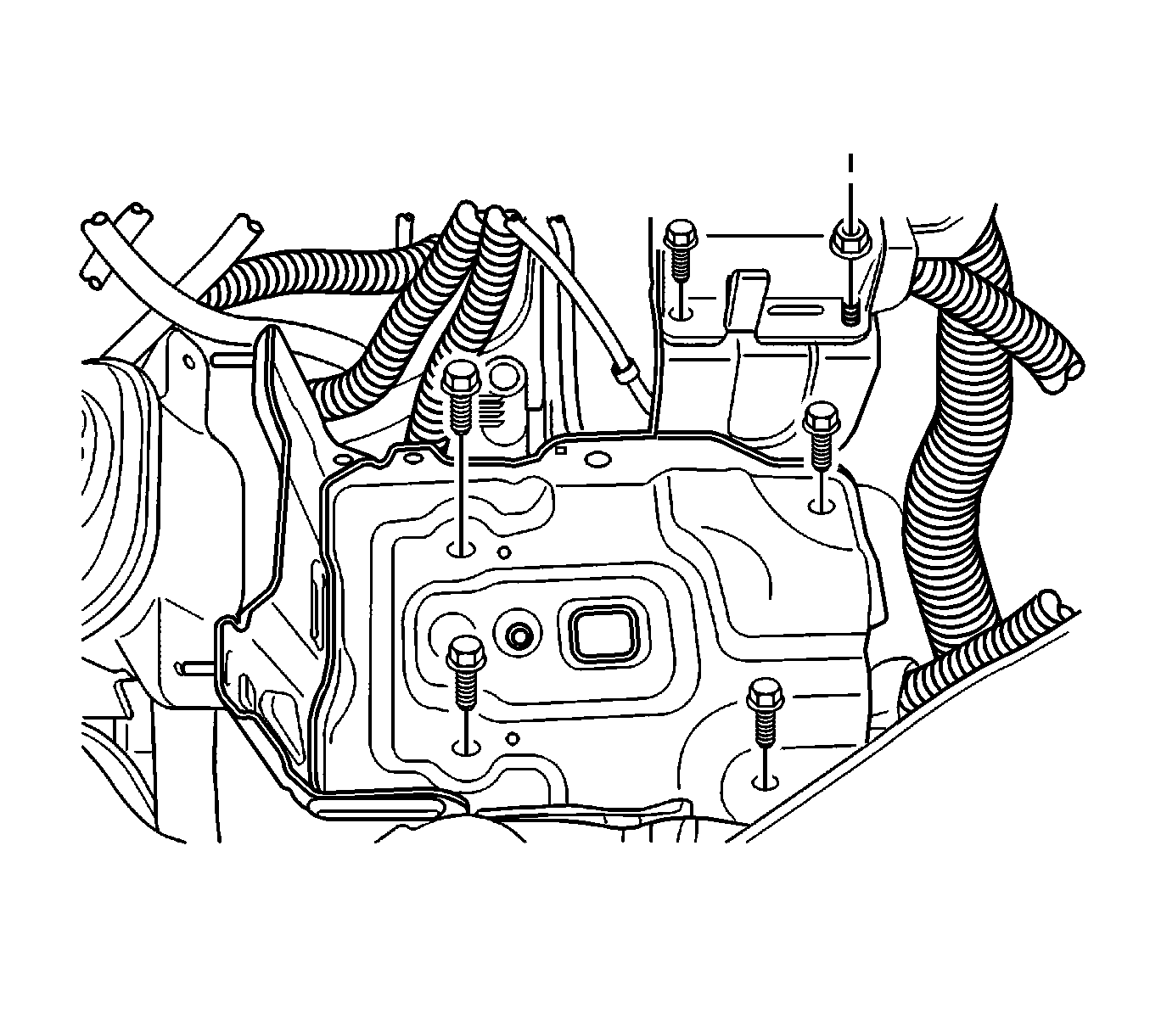
- Remove the battery and battery tray. Refer to Battery Tray Replacement .
- Remove the fuse box cover.
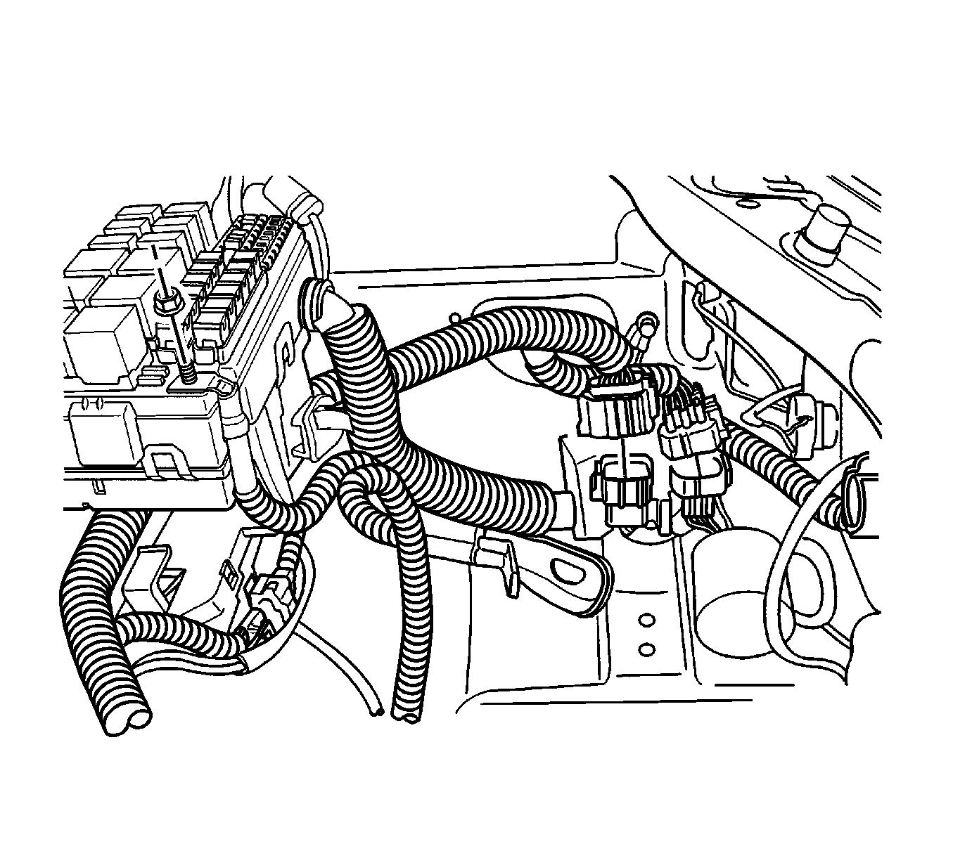
- Remove the battery lead nut at the fuse box.
- Disconnect the battery lead at the fuse box.
- Disconnect the engine wiring harness connectors.
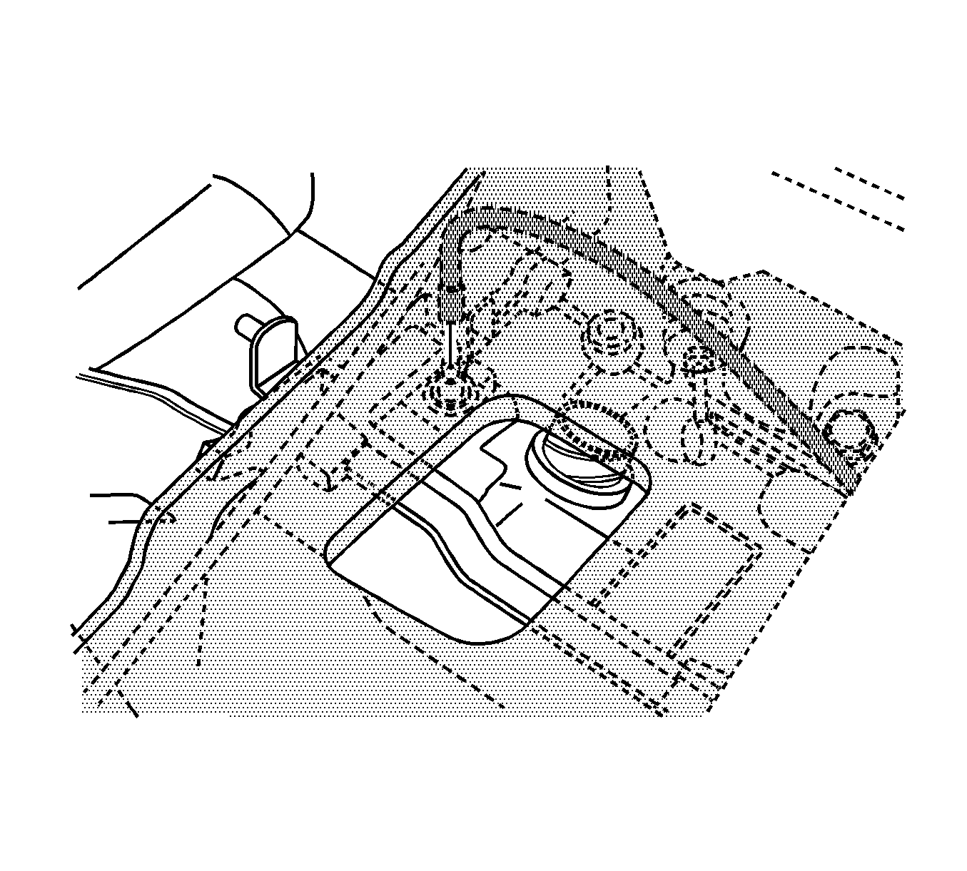
- Remove the surge tank. Refer to Radiator Surge Tank Replacement .
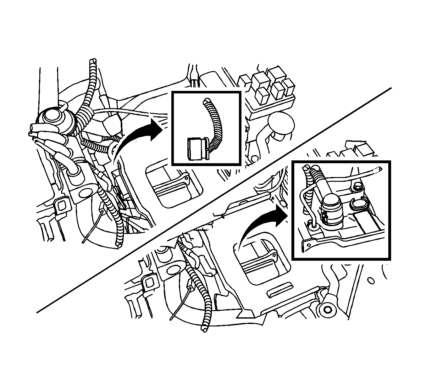
- Disconnect the transaxle wiring harness connector from the transaxle case.
- Disconnect the P/N switch connector from the transaxle case.
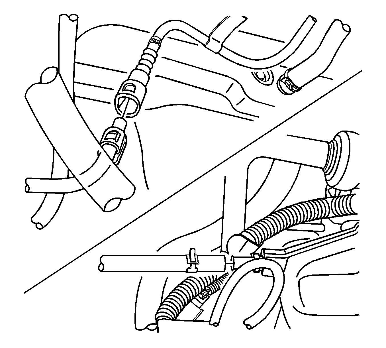
- Disconnect the air breather hose from the transaxle case.
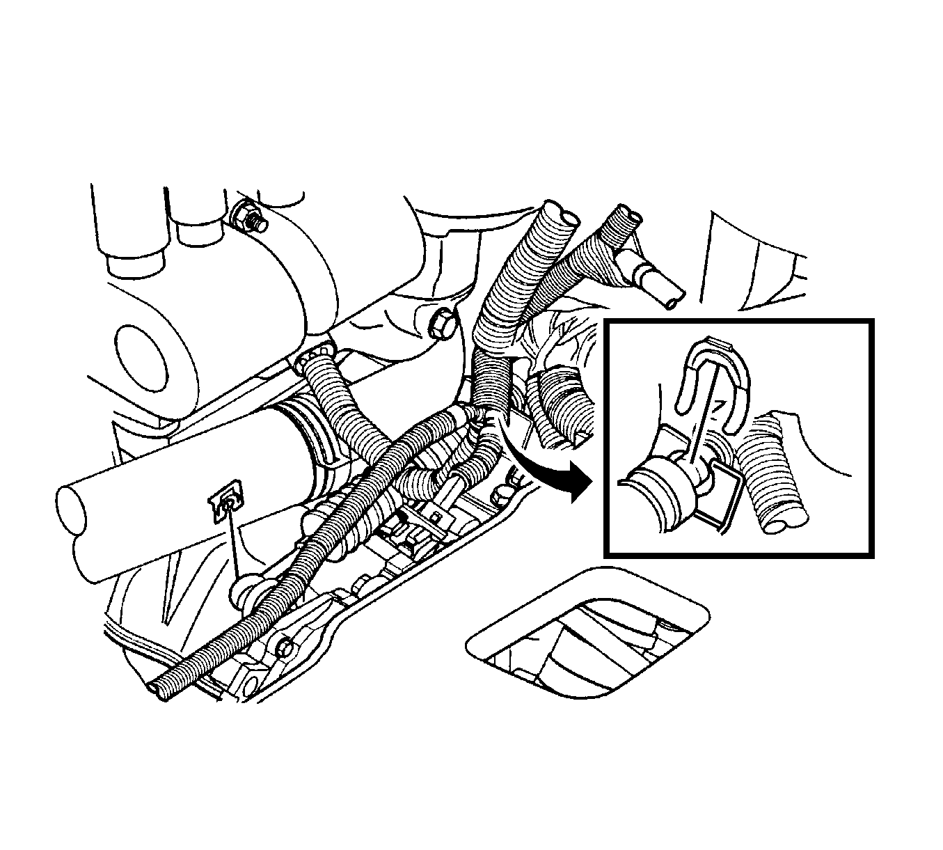
- Remove the clip from the selector lever connection on the transaxle case and disconnect the shift control cable from the selector lever connection.
- Remove the clip from the shift control cable at the transaxle mount connection.
- Disconnect the shift control cable from the transaxle mount.
- Disconnect the breather hose at the valve cover.
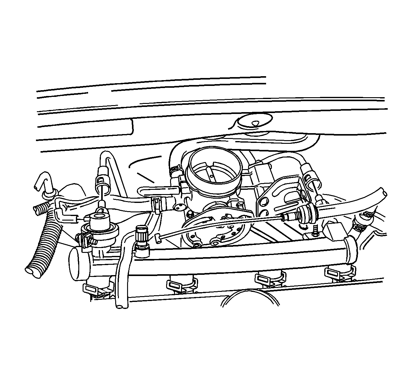
- Disconnect the throttle cable at the throttle body and the intake manifold.
- Disconnect the fuel feed line at the fuel rail.
- Disconnect the fuel return line at the fuel pressure regulator.
- Disconnect the upper radiator hose at the thermostat housing.
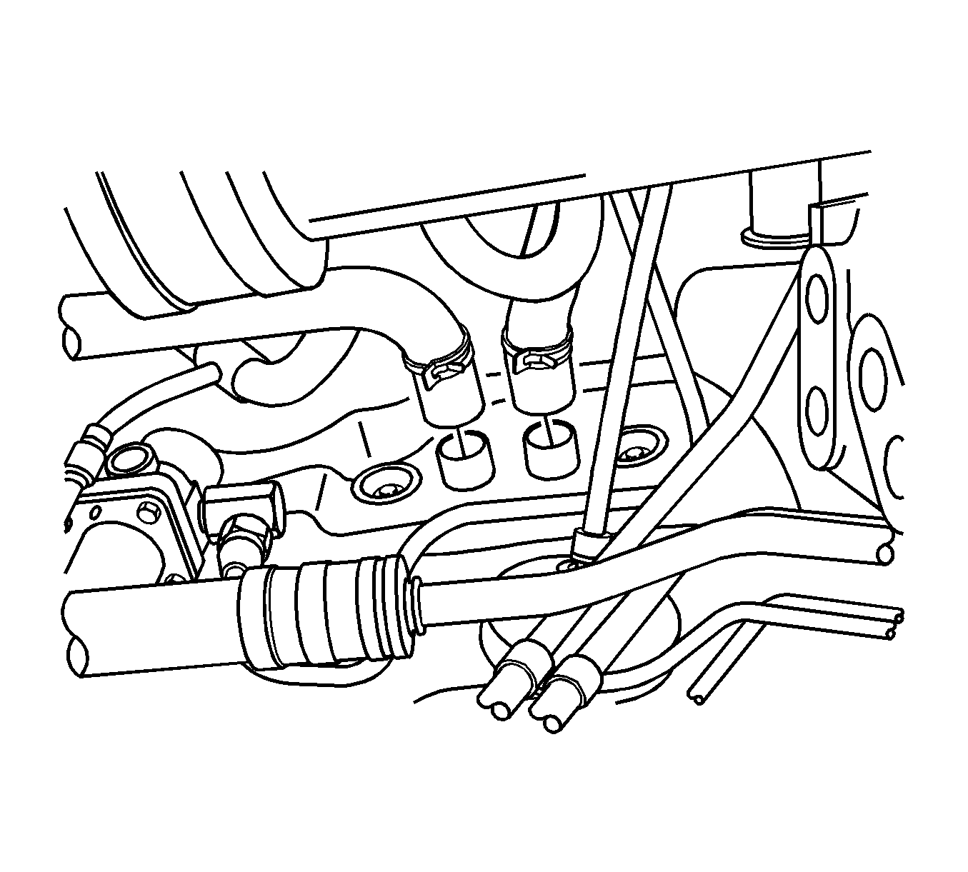
- Disconnect the power steering pressure hose and the power steering suction hose from the power steering pump.
- Disconnect the A/C compressor hose assembly and the connector from the compressor. Refer to Suction Hose Replacement .
- Remove the front wheel. Refer to Tire and Wheel Removal and Installation .
- Remove the front wheel well splash shield.
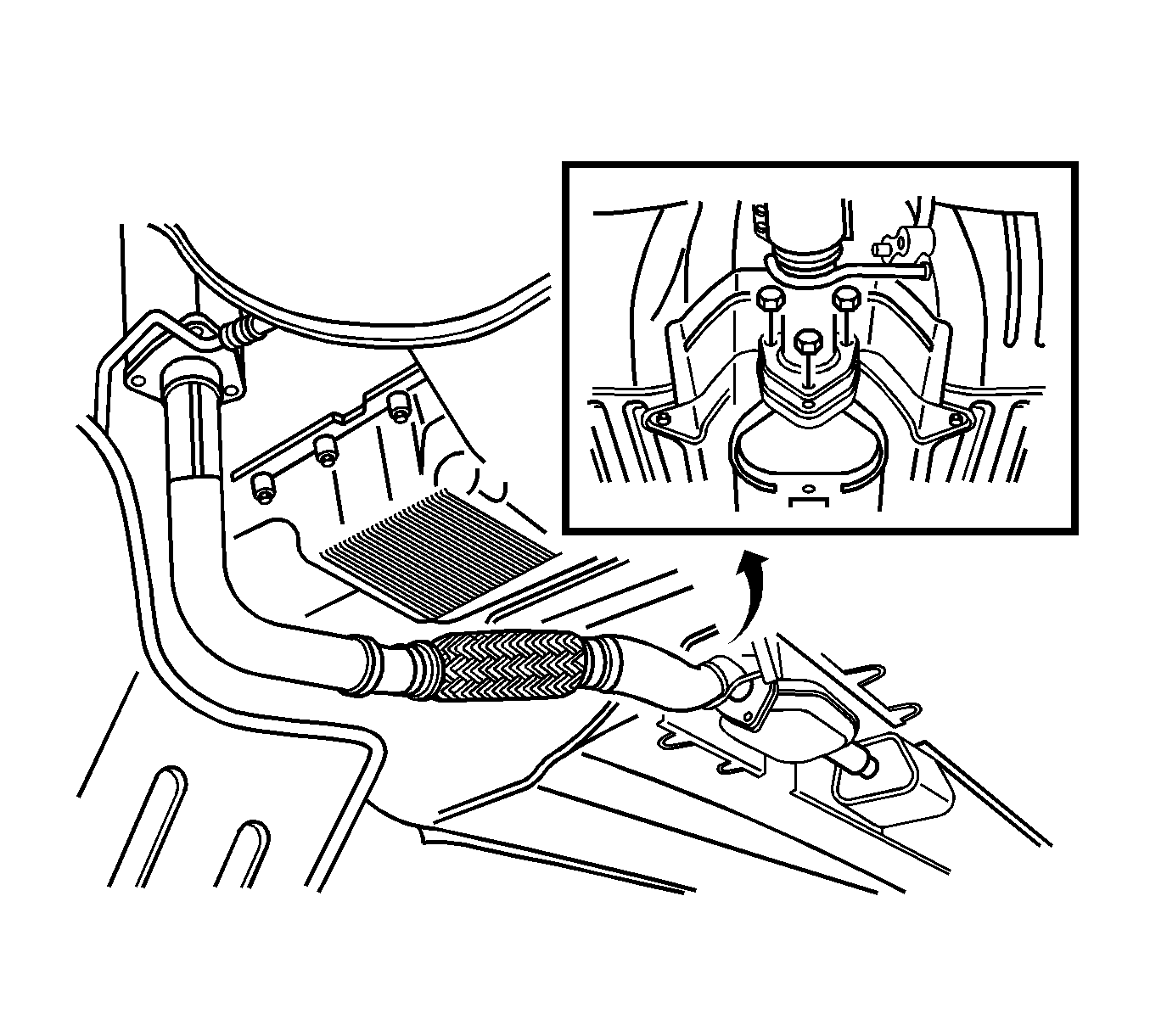
- Remove the front exhaust pipe. Refer to Front Pipe Replacement .
- Disconnect the heater inlet hose at the heater core.
- Disconnect the heater outer hose at the heater core.
- Disconnect the vacuum line from the charcoal canister purge solenoid.
- Disconnect the brake vacuum hose at the intake manifold.
- Disconnect the A/C compressor connector at the A/C compressor coil.
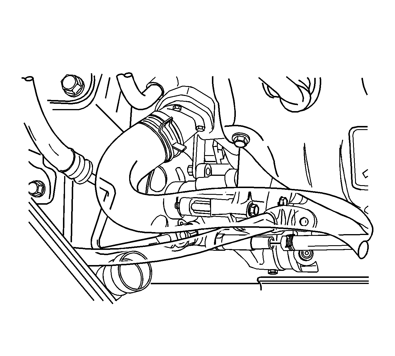
- Disconnect the lower radiator hose from the coolant pipe.
- Disconnect the fluid cooler inlet hose from the transaxle.
- Disconnect the fluid cooler outlet hose from the transaxle.
- Remove the lower engine mount. Refer to Engine Mount Replacement .
- Remove the cross member.
- Disconnect the drive axle assembly from the transaxle.
- Using the J 39580 , support the engine and transaxle.
- Remove the right side engine mount. Refer to Engine Mount Replacement .
- Remove the transaxle mount. Refer to Transmission Mount Bracket Replacement .
- Slowly lift the vehicle.
- Disconnect the engine assembly from the transaxle assembly. Refer to Transmission Replacement .
Notice: If the engine is damaged internally and a new engine assembly is installed in the vehicle, ensure that all foreign material is flushed out of the cooling system. You must also flush out the oil cooler system. Failure to rid the oil cooler system of debris can result in engine damage.
Important: On vehicles equipped with manual transaxle, the manual transaxle must be removed before the engine is removed. Refer to Transmission Replacement .
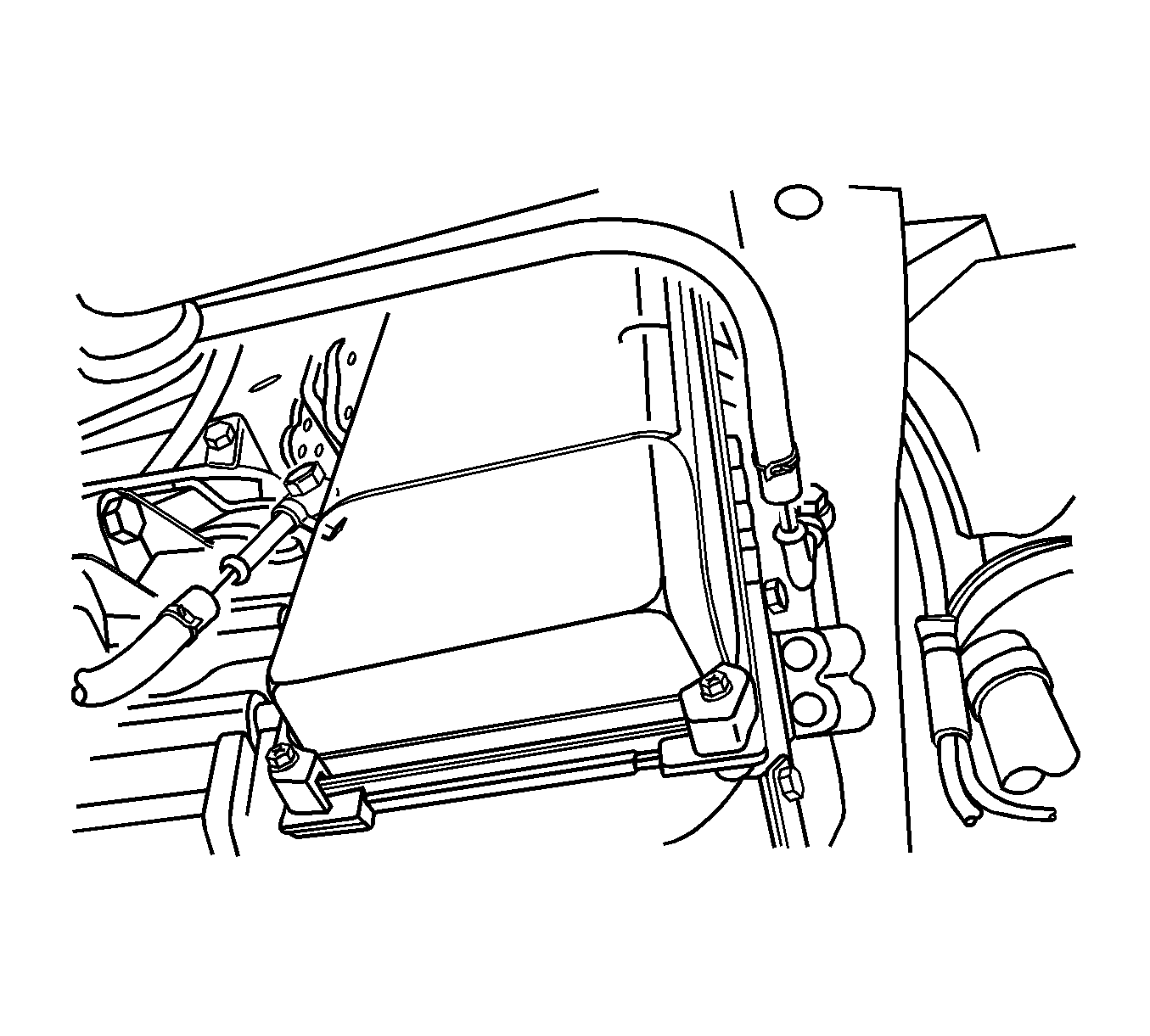
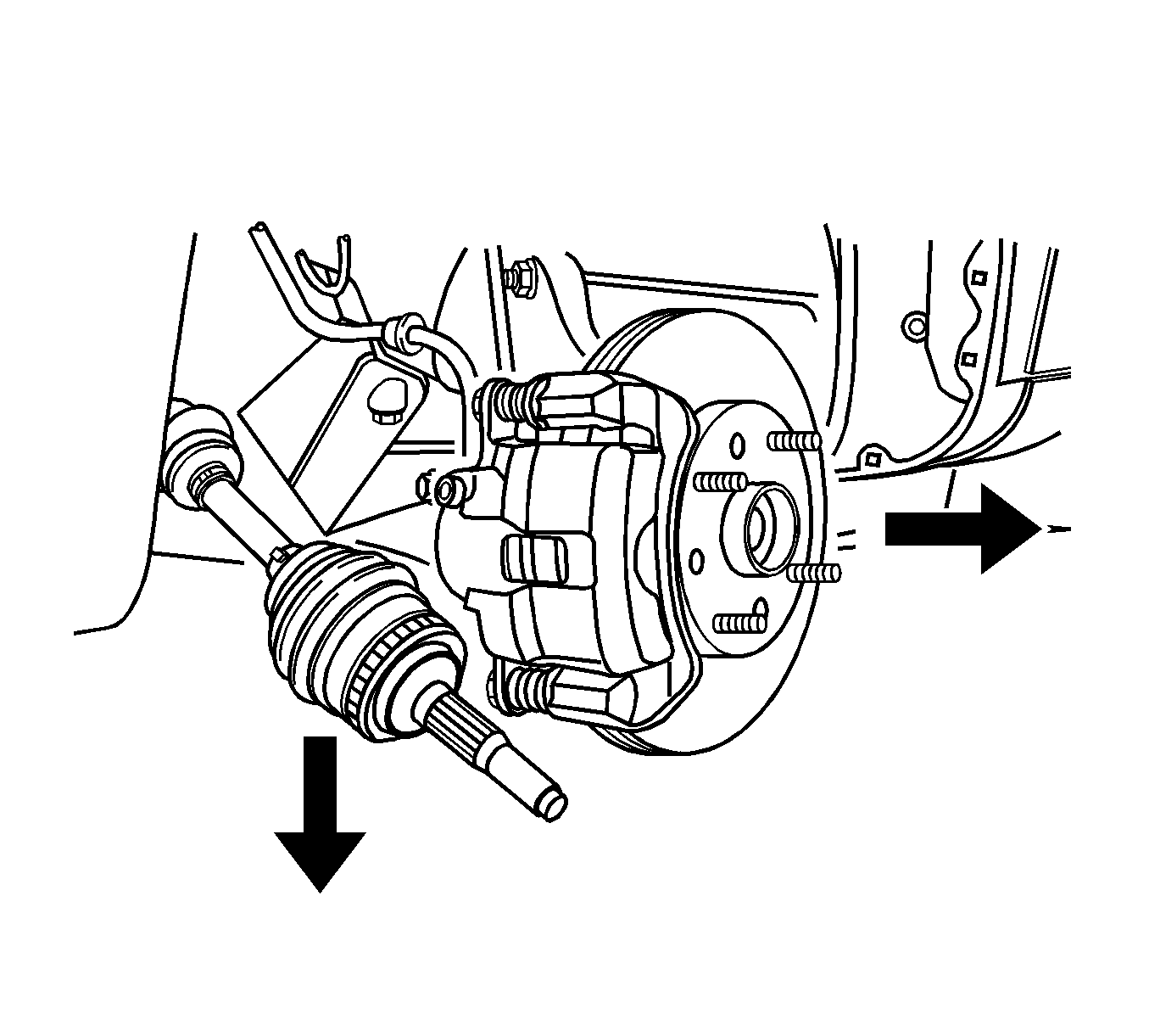
Notice: Refer to Engine Lifting Notice in the Preface section.
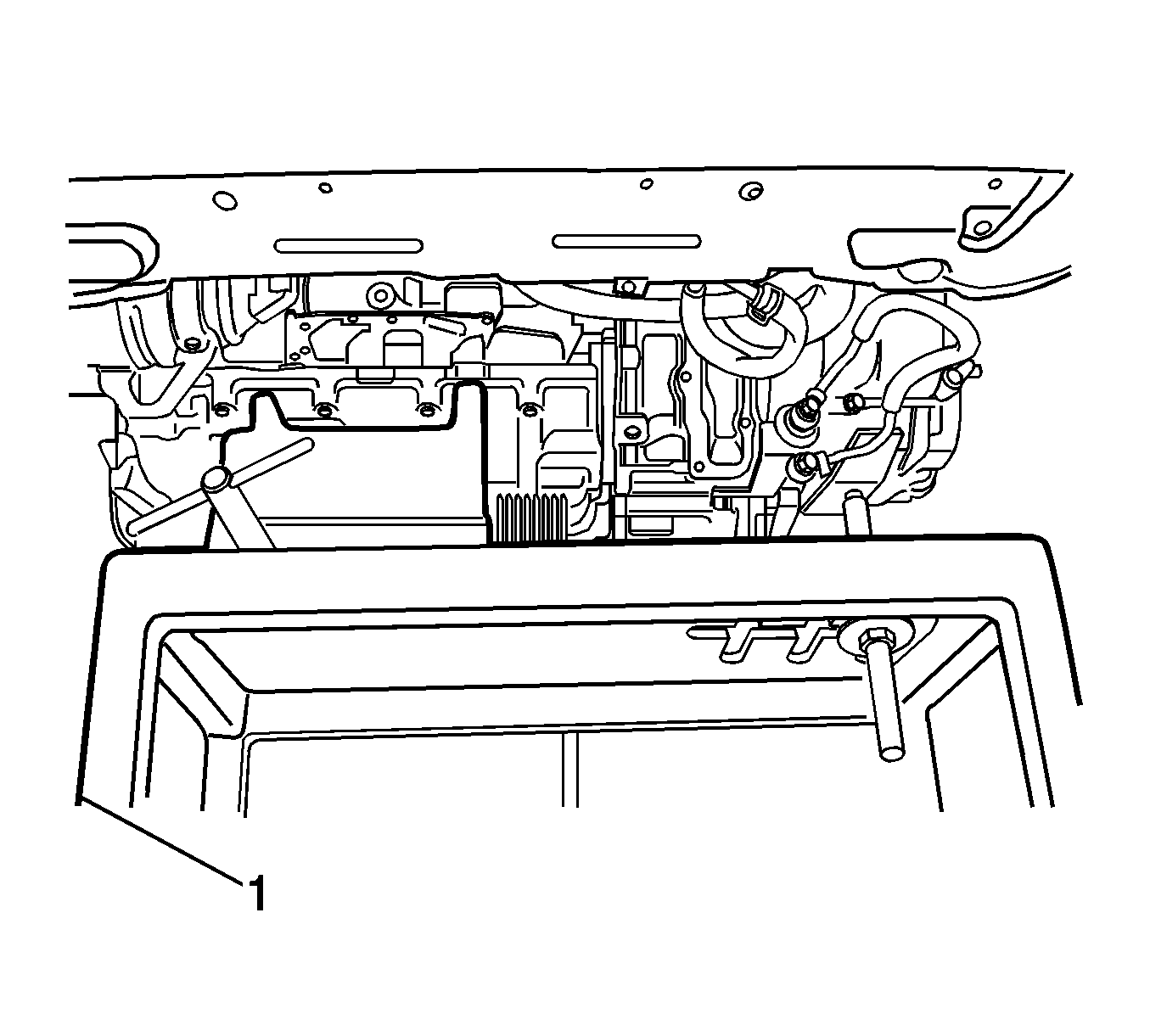
Notice: Refer to Vehicle Lifting and Jacking Notice in the Preface section.
Installation Procedure
- Install the engine assembly to the transaxle assembly. Refer to Transmission Replacement .
- Slowly lower the vehicle.
- Using the J 39580 , support the engine and the transaxle.
- Install the transaxle mount. Refer to Transmission Mount Bracket Replacement .
- Install the right side engine mount. Refer to Engine Mount Replacement .
- Connect the drive axle assembly from the transaxle.
- Install the cross member.
- Install the lower engine mount. Refer to Engine Mount Replacement .
- Connect the fluid cooler outlet hose from the transaxle.
- Connect the fluid cooler inlet hose from the transaxle.
- Connect the lower radiator hose at the coolant pipe.
- Connect the A/C compressor connector at the A/C compressor coil.
- Connect the brake vacuum hose at the intake manifold.
- Connect the vacuum line from the charcoal canister purge solenoid.
- Connect the heater outer hose at the heater core.
- Connect the heater inlet hose at the heater core.
- Install the front exhaust pipe. Refer to Front Pipe Replacement .
- Install the front wheel well splash shield.
- Install the front wheel. Refer to Tire and Wheel Removal and Installation .
- Connect the A/C compressor hose assembly and the connector from the compressor. Refer to Suction Hose Replacement .
- Connect the power steering pressure hose and the power steering suction hose from the power steering pump.
- Connect the upper radiator hose at the thermostat housing.
- Connect the fuel return line at the fuel pressure regulator.
- Connect the fuel feed line at the fuel rail.
- Connect the throttle cable at the throttle body and the intake manifold.
- Connect the breather hose at the valve cover.
- Connect the shift control cable from the transaxle mount.
- Install the clip from the shift control cable at the transaxle mount connection.
- Install the clip from the selector lever connection on the transaxle case and disconnect the shift control cable from the selector lever connection.
- Connect the air breather hose from the transaxle case.
- Connect the P/N switch connector from the transaxle case.
- Connect the transaxle wiring harness connector from the transaxle case.
- Install the surge tank. Refer to Radiator Surge Tank Replacement .
- Connect the engine wiring harness connectors.
- Connect the battery lead at the fuse box.
- Install the battery lead nut at the fuse box.
- Install the fuse box cover.
- Install the battery and battery tray. Refer to Battery Tray Replacement .
- Recharge the air conditioning system, if equipped. Refer to Refrigerant Recovery and Recharging .
- Fill the engine coolant. Refer to Cooling System Draining and Filling .
- Connect the air intake tube from the throttle body.
- Connect the breather hose from the valve cover.
- Connect the manifold intake temperature sensor connector.
- Install the air inlet duct bolts to the air inlet duct.
- Install the air filter housing bolts and the air filter assembly.
- Install the fuel pump fuse.
- Fill the crankcase with engine oil.
- Connect the negative battery cable.
- Start the engine and inspect for leaks.

Notice: If the engine is damaged internally and a new engine assembly is installed in the vehicle, ensure that all foreign material is flushed out of the cooling system. You must also flush out the oil cooler system. Failure to rid the oil cooler system of debris can result in engine damage.
Notice: Refer to Engine Lifting Notice in the Preface section.
Notice: Refer to Fastener Notice in the Preface section.
Tighten
Tighten the oil pan flange-to-transaxle bolts to 40 N·m (30 lb ft).


Tighten
Tighten the catalytic converter-to-connecting pipe nuts to 30 N·m (22 lb ft).


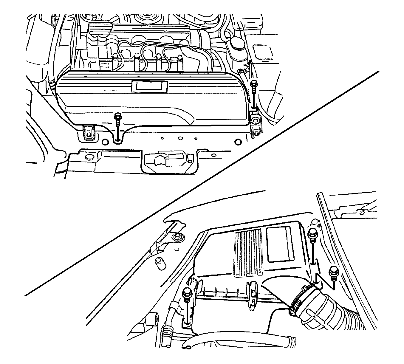
Tighten
Tighten the air inlet duct bolts to 8 N·m (71 lb in).
Tighten
Tighten the air filter housing bolts to 8 N·m (71 lb in).
