For 1990-2009 cars only
Tools Required
| • | DT 46474 (DW260-060) Brake F Cup Spring Compressor |
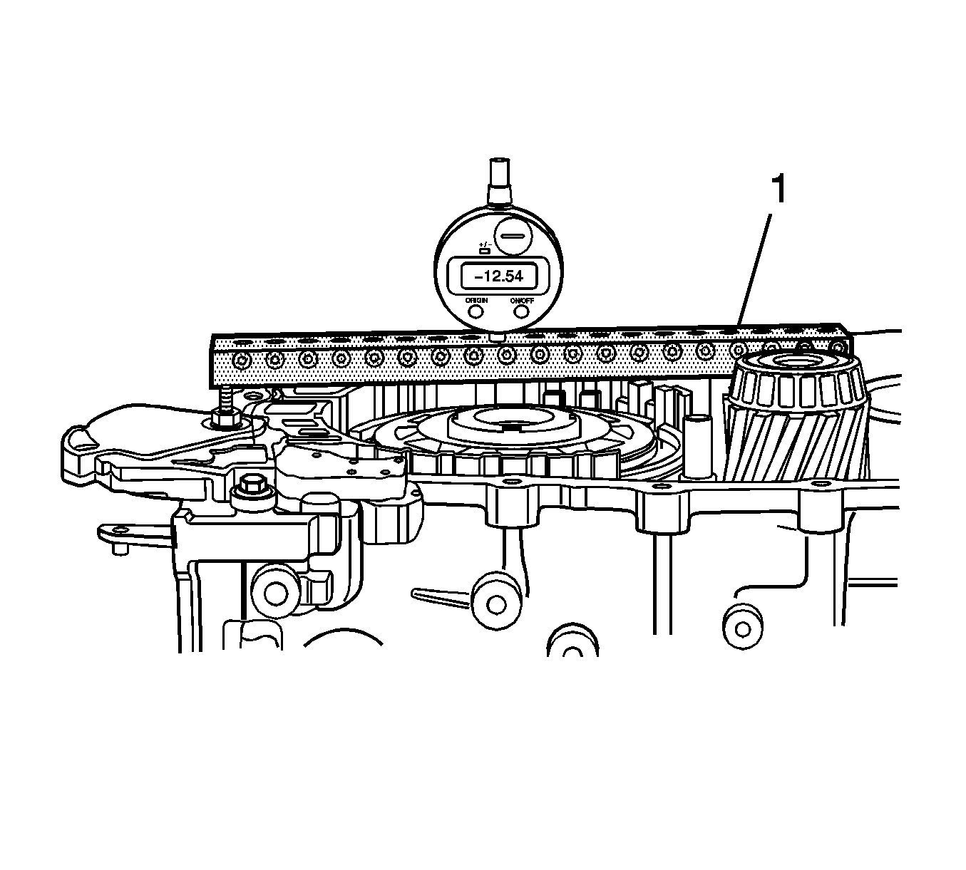
| • | DT 46479 (DW260-110) Brake F Disc Clearance Measuring Bar |
- Install piston F and the bearing plate with the spur gear.
- Install the cup spring.
- Install the brake F split stop-ring.
- Install the brake F inner disc carrier.
- Install the disc set.
- Install the side shaft. Refer to Side Shaft Installation .
Caution: Refer to Safety Glasses Caution in the Preface section.
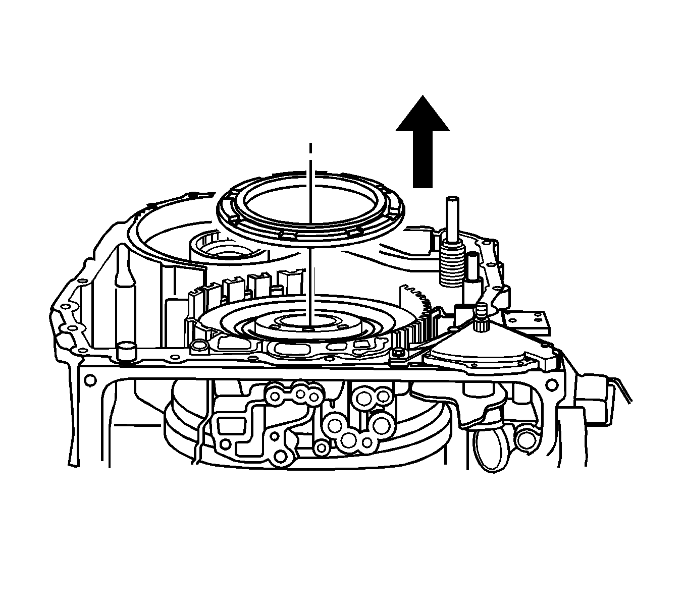
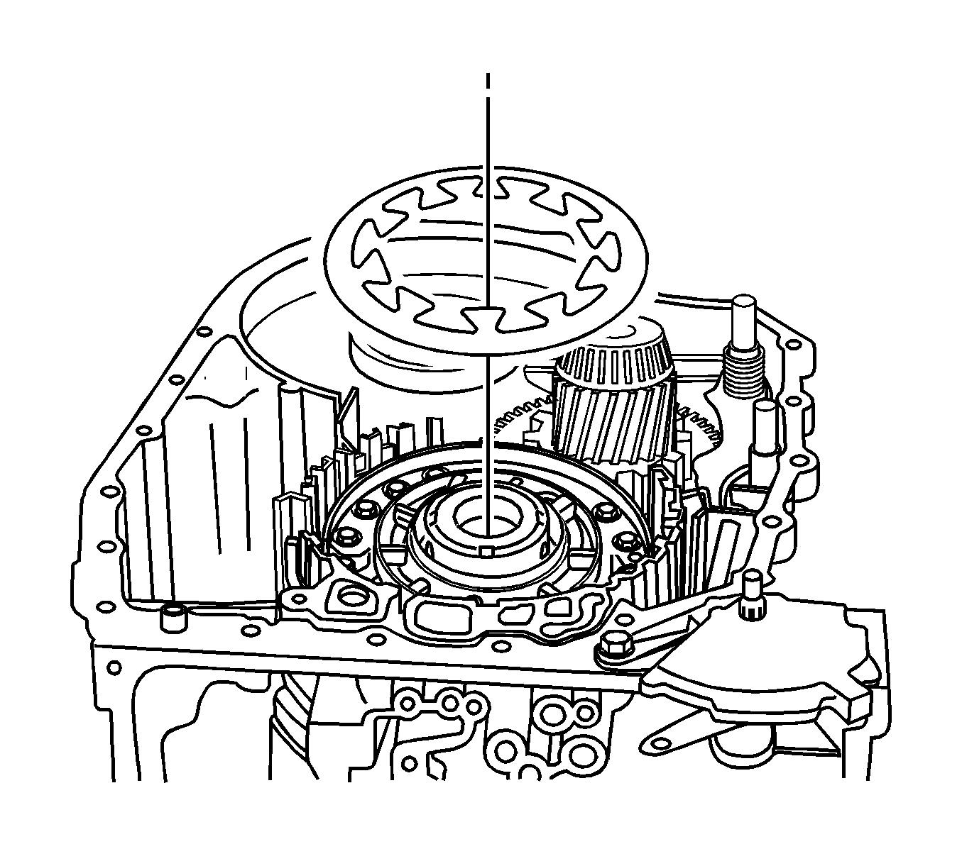
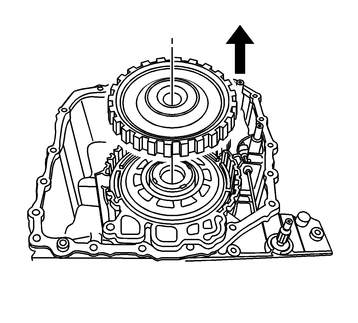
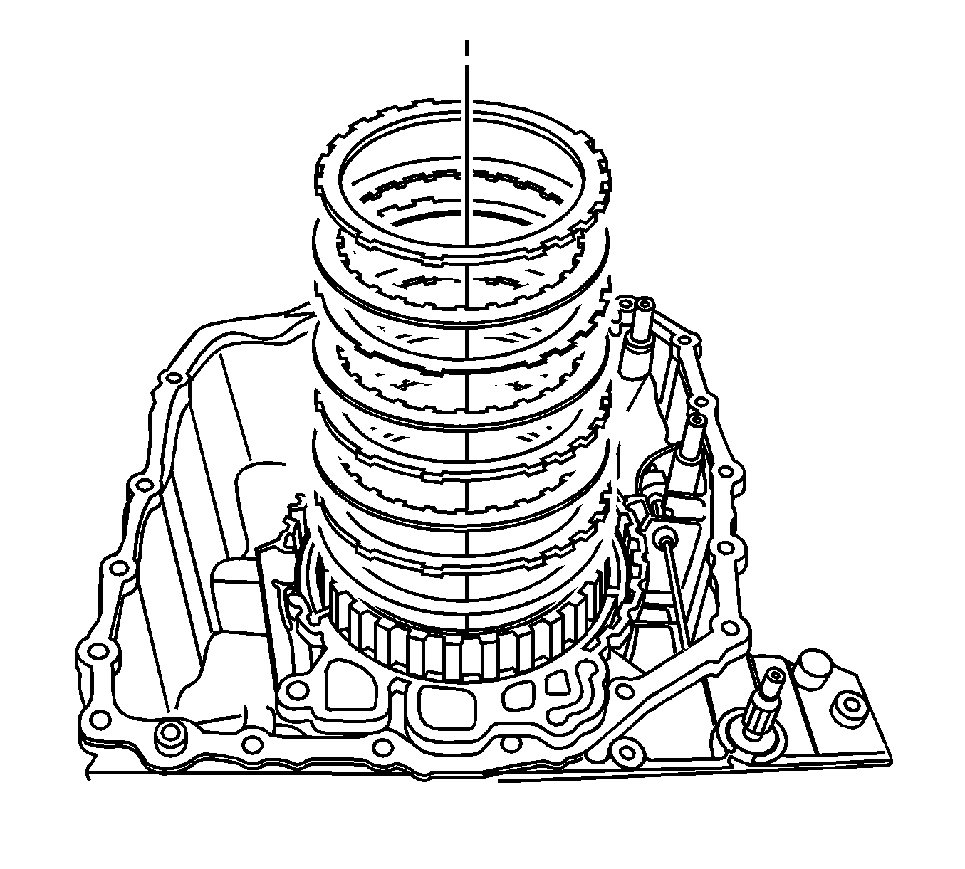
Measuring Installation Space F
- Using a DT 46479 (1), measure from the transaxle housing sealing surfaces to the piston's disc support surface at 2 opposing points, M1, M2.
- Average the measurement values M1, M2 = BF.
Calculation
| • | BF is (M1+M2)/2 |
| • | M1 = 18.6 mm (0.73 in) |
| • | M2 = 18.8 mm (0.74 in) |
| • | BF = 18.7 mm (0.735 in) |
Determining Adjusting Disc F
- Calculate the test dimension PF (PF = BF-MF).
- Find the disc set's thickness. Refer to Transmission General Specifications .
- Replace clutch B's setting disc 3.0 mm (0.12 in).
BF = installation space
MF = disc set thickness assume 14.50 (0.57 in)
EXAMPLE
BF = 18.70 mm (0.735 in)
MF = 14.50 mm (0571 in)
PF = 4.2 mm (0.164 in)
PF is 4.20 mm (0.164 in) so, the disc set's thickness is 3.0 mm (0.12 in).
