For 1990-2009 cars only
Description
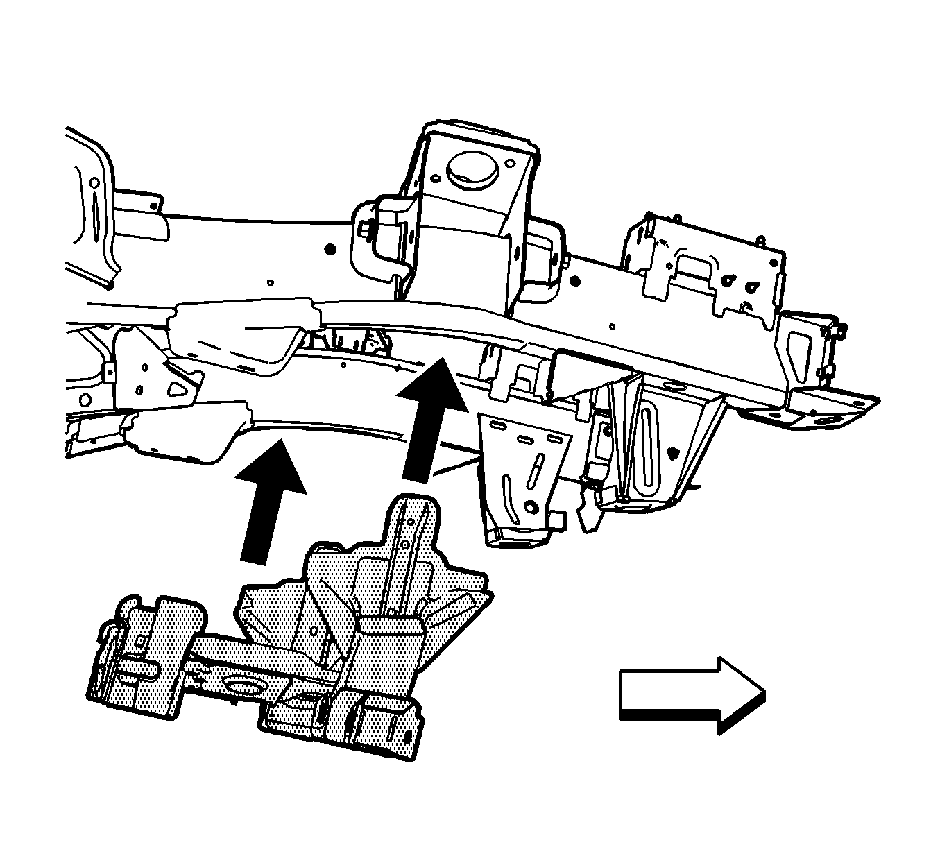
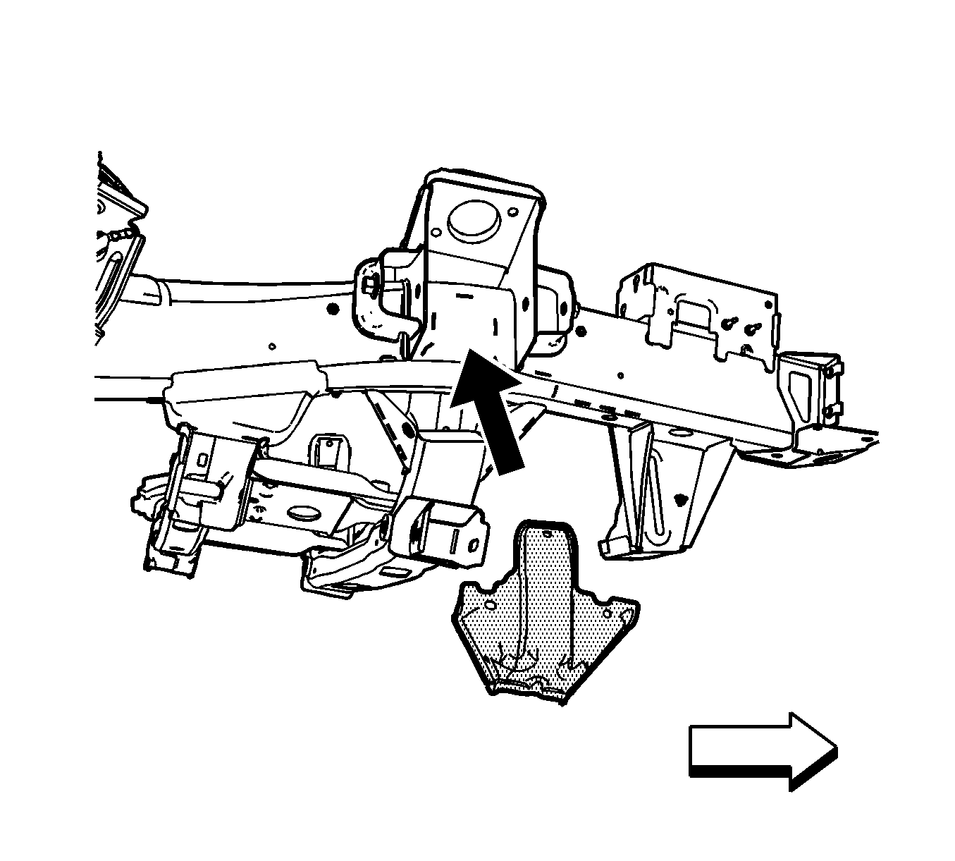
The replacement front crossmember assembly is serviced as a kit with an instruction sheet. Parts with the kit include the front crossmember, and the left and the right outer crossmember brackets. You must replace the left and the right outer crossmember brackets in order to replace the front crossmember.
Removal Procedure
- Disable the SIR system. Refer to SIR Disabling and Enabling .
- Disconnect the negative battery cable. Refer to Battery Negative Cable Disconnection and Connection .
- Remove all related panels and components.
- Repair as much of the damage as possible to factory specifications. Refer to Dimensions - Body .
- Note the location and remove the sealers and anti-corrosion materials from the repair area, as necessary. Refer to Anti-Corrosion Treatment and Repair .
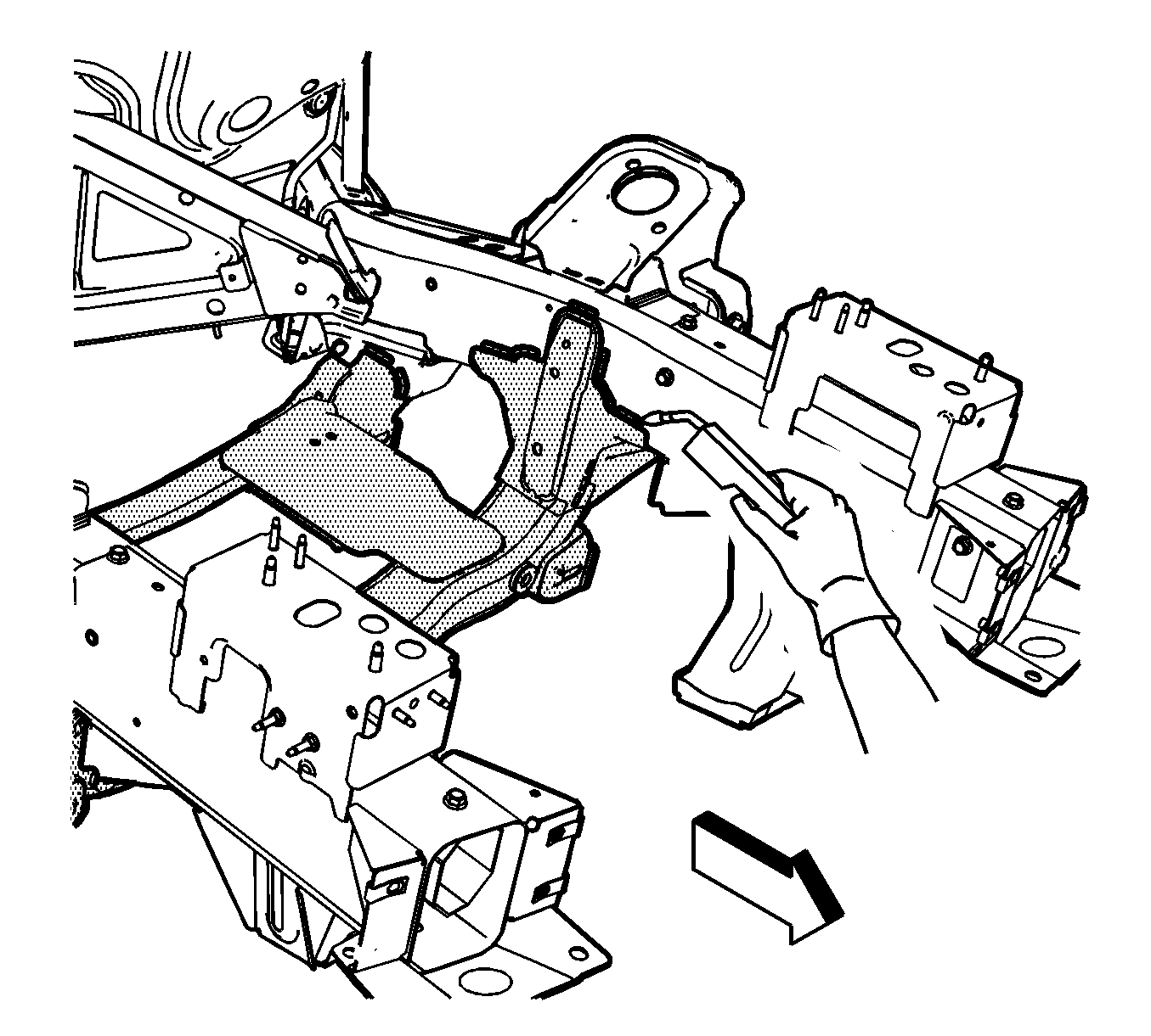
- Locate and remove all factory welds attaching the left and right outer crossmember brackets to the frame rail. Note the number and location of the welds for installation of the new crossmember outer brackets.
- Locate and remove all factory welds attaching the crossmember to the frame rails and attaching brackets. Note the number and location of the welds for installation of the new crossmember.
- Remove the damaged crossmember.
Caution: Refer to Approved Equipment for Collision Repair Caution in the Preface section.
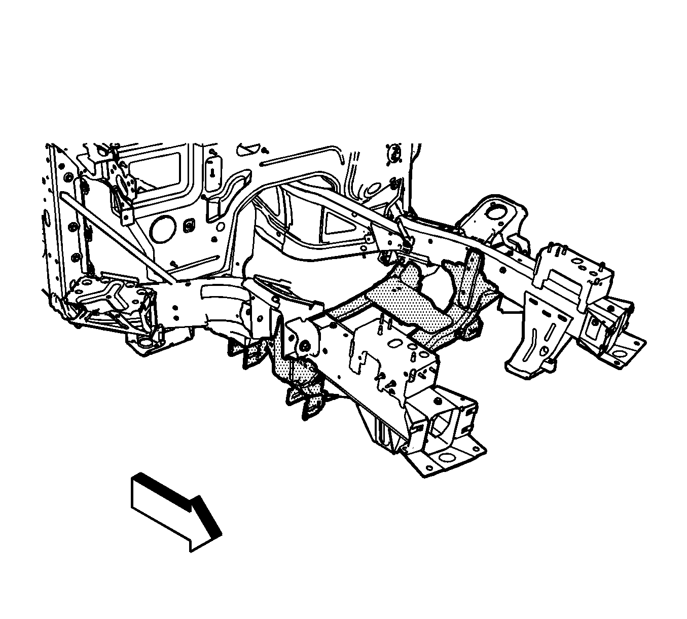
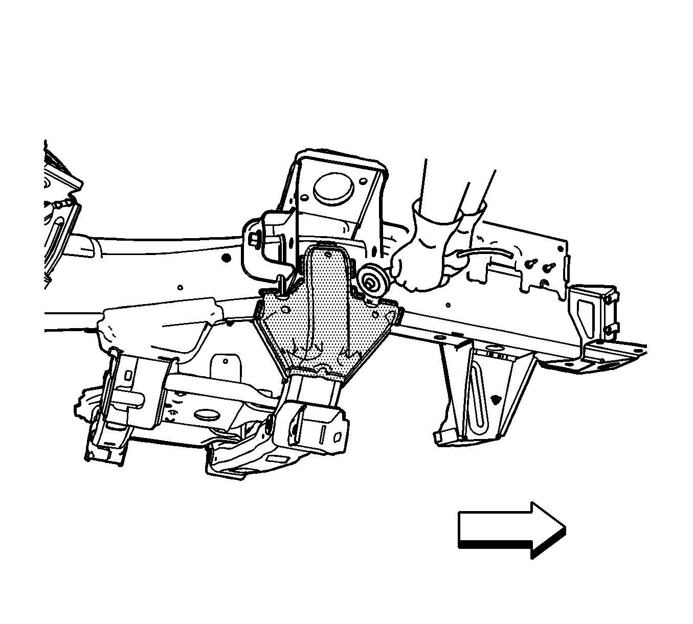
Important: When removing the welds, favor the crossmember bracket side of the weld joint. Do not damage the frame rails.
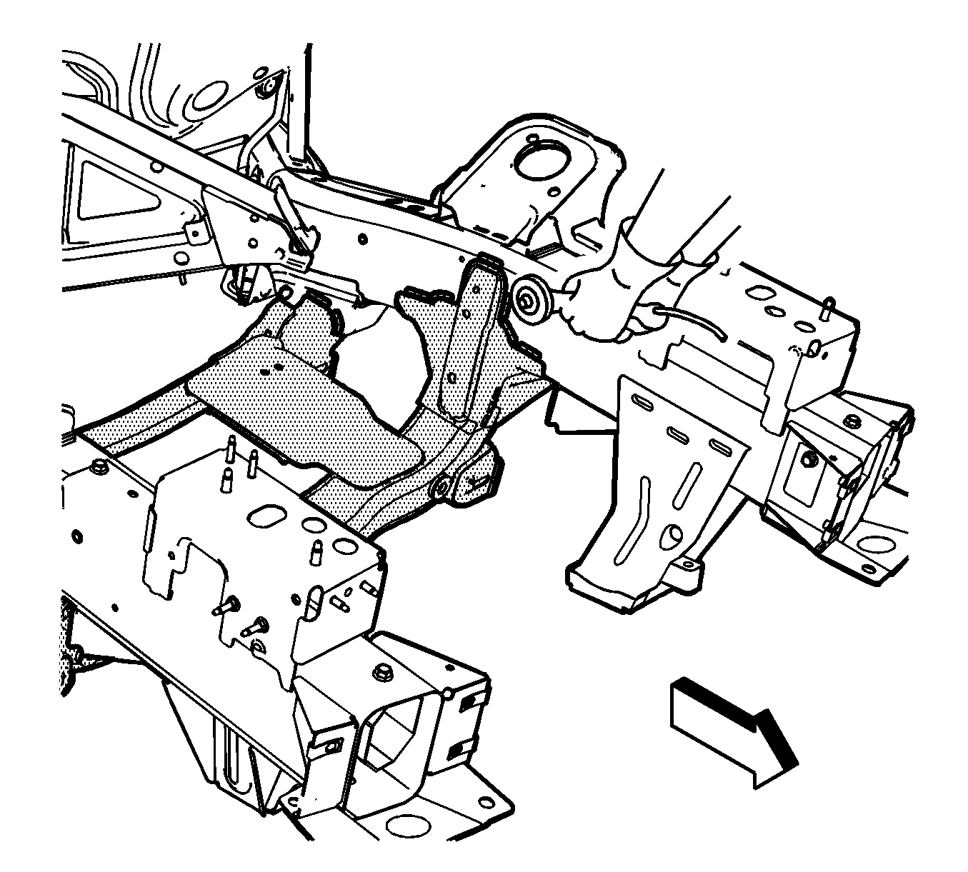
Important: When removing the welds, favor the crossmember side of the weld joint. Do not damage the frame rails or the attaching brackets.
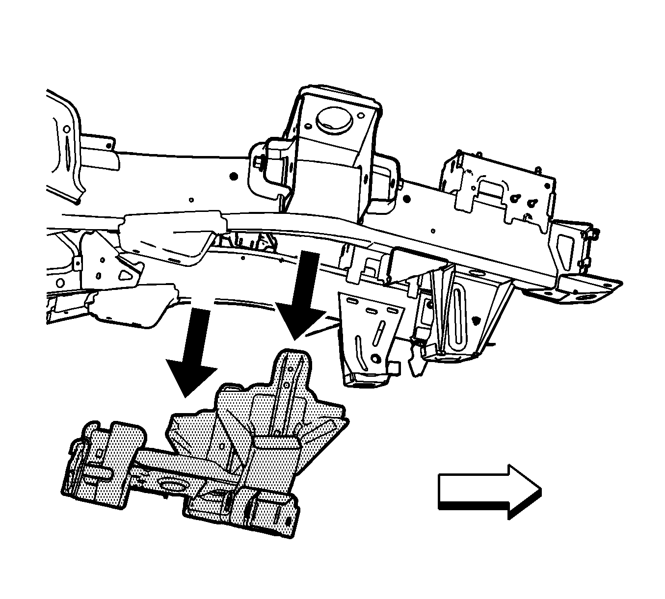
Installation Procedure
- Prepare all mating surfaces as necessary for welding
- Apply GM-approved Weld-Thru Coating or equivalent to all mating surfaces. Refer to Anti-Corrosion Treatment and Repair .
- Position the crossmember to the vehicle. Ensure proper positioning of the crossmember by using 3-dimensional measuring equipment. Clamp the crossmember into place.
- Using a MIG-welder, weld the crossmember to the vehicle, duplicating the factory welds.
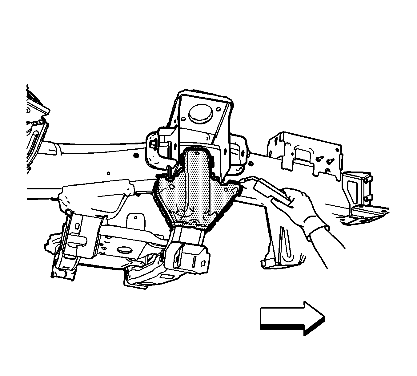
- Position the outer crossmember outer crossmember brackets to the vehicle. Ensure proper positioning of the crossmember by using 3-dimensional measuring equipment. Clamp the crossmember into place.
- Using a MIG-welder, weld the crossmember brackets assembly to the vehicle, duplicating the factory welds.
- Clean and prepare all welded surfaces.
- Apply the sealers and anti-corrosion materials to the repair area, as necessary. Refer to Anti-Corrosion Treatment and Repair .
- Paint the repair area. Refer to Paint Identification .
- Install all related panels and components.
- Connect the negative battery cable. Refer to Battery Negative Cable Disconnection and Connection .
- Enable the SIR system. Refer to SIR Disabling and Enabling .
