For 1990-2009 cars only
Removal Procedure
- Remove the instrument panel (I/P) lower closeout panel. Refer to Instrument Panel Insulator Panel Replacement - Left Side.
- Remove the accelerator pedal assembly from the brake pedal bracket to improve access to the brake pedal pivot nut. Refer to Accelerator Pedal Position Sensor Replacement.
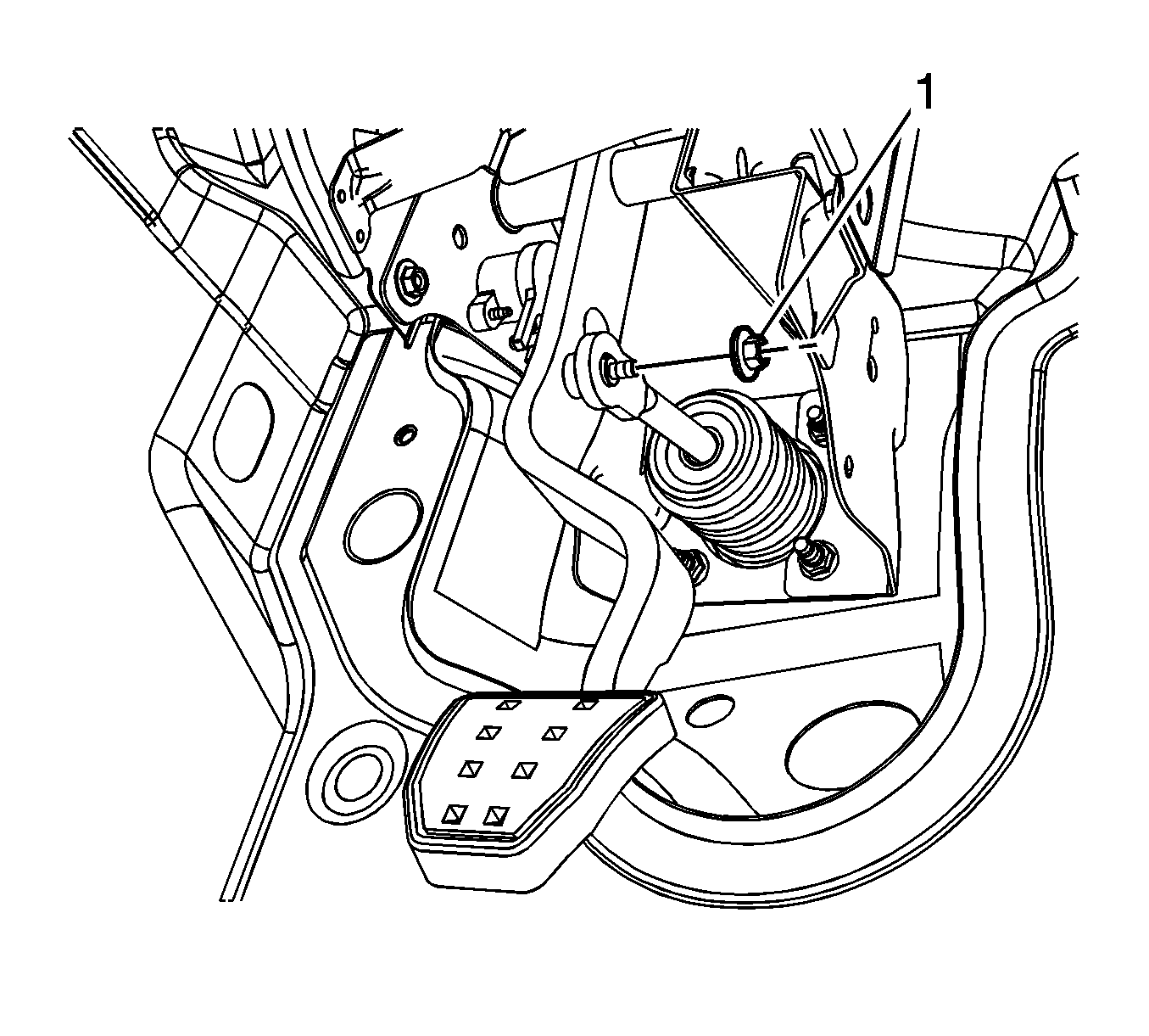
- Remove the power brake booster pushrod nut (1).
- Disconnect the power brake booster pushrod from the power brake booster pushrod pin.
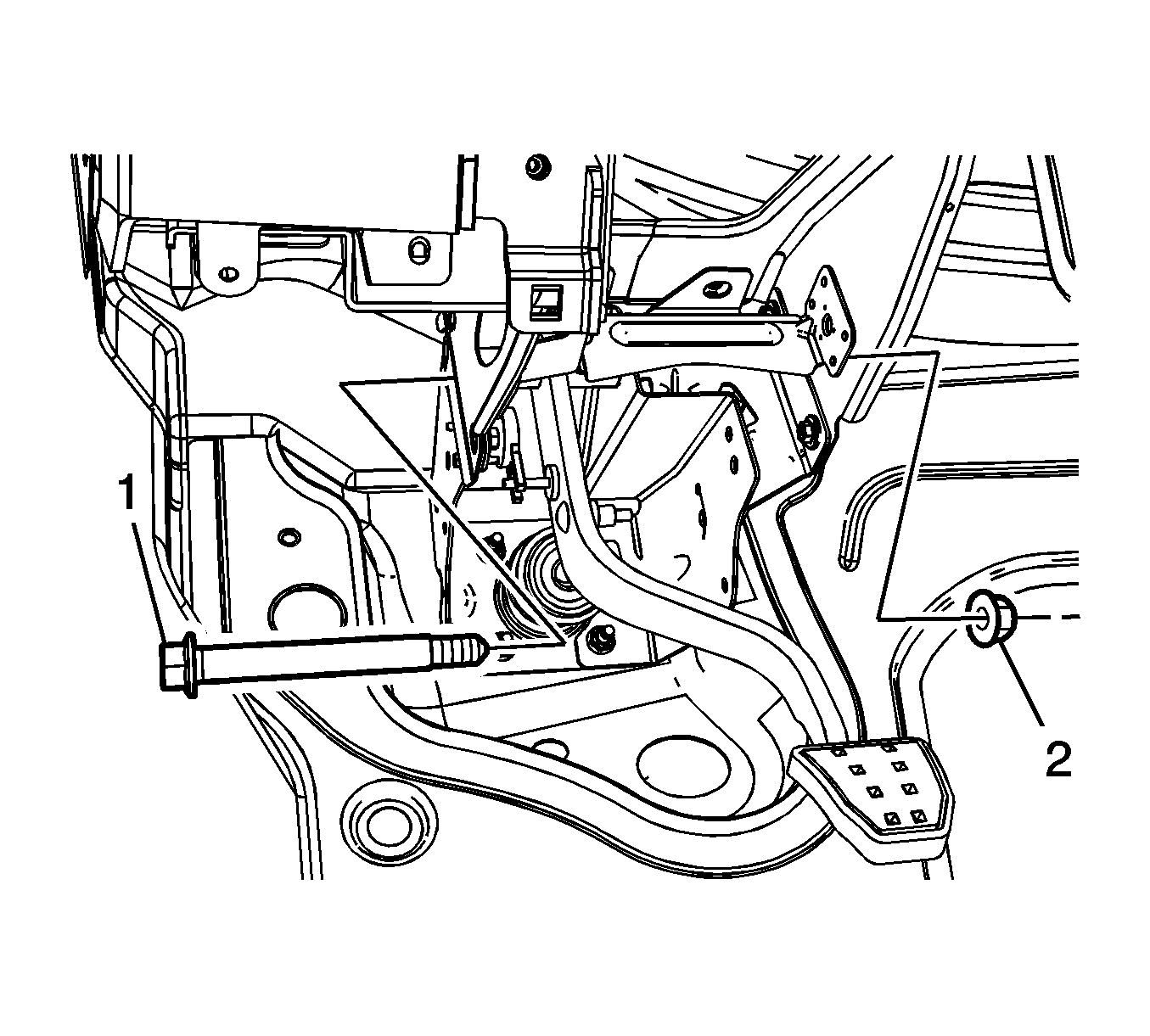
- While holding the brake pedal pivot bolt (1) stationary, remove the brake pedal pivot nut (2).
- Remove the brake pedal assembly and pivot bushings.


Installation Procedure
- Apply a thin coat of high-temperature grease GM P/N 12345996 (Canadian P/N 10953501) to the brake pedal pivot bushing, the pushrod washer, the push rod pin on the pedal, and the brake pedal pivot pin.
- Install the brake pedal assembly and pivot bushings.
- Install the brake pedal pivot bolt (1).
- Loosely install the brake pedal pivot nut (2).
- While holding the brake pedal pivot bolt stationary, tighten the brake pedal pivot nut to 50 N·m (37 lb ft).
- Connect the power brake booster pushrod to the power brake booster pushrod pin.
- Install the power brake booster pushrod nut (1) and tighten to 10 N·m (89 lb in).
- Install the accelerator pedal assembly. Refer to Accelerator Pedal Position Sensor Replacement.
- Install the instrument panel (I/P) lower closeout panel. Refer to Instrument Panel Insulator Panel Replacement - Left Side.
- Calibrate the brake pedal position sensor. Refer to Brake Pedal Position Sensor Calibration.

Ensure the brake pedal position switch actuator pin is engaged in the fork of the brake pedal position sensor.
Caution: Refer to Fastener Caution in the Preface section.

