For 1990-2009 cars only
Special Tools
| • | J 36850 Assembly Lubricant |
| • | J 39068 Valve Body Guide Pins |
For equivalent regional tools, refer to Special Tools.
- Install J 39068 Valve Body Guide Pins onto the front and rear control valve bodies.
- Using a light coat of transmission fluid on both sides of the spacer plate (307), install NEW gaskets (305, 309) onto the spacer plate.
- Install the NEW solenoid valve filter assemblies (308, 312) onto the control valve body spacer plate (307).
- Install the control valve body spacer plate (307) and gaskets (305, 309) as an assembly onto the valve bodies.
- Use J 36850 lubricant to install the 12 checkballs (306) onto the channel plate (304). Refer to Ball Check Valve Locations.
- Using a light coating of transmission fluid, install a NEW gasket (303) onto the channel plate (304).
- Install the control valve body channel plate (304) and gasket (303) as an assembly.
- Use J 36850 lubricant to install the control valve channel plate check ball spring (302) onto the channel plate.
- Install the control valve channel plate (301) onto the channel plate gasket.
- Install the control valve body bolts (300) into the valve body. Tighten the control valve body bolts (300) to 11 N·m (8 lb ft).
- Remove the J 39068 Valve Body Guide Pins from the valve body.
- Install the direct clutch accumulator piston fluid seal rings (314, 316) onto the direct clutch accumulator piston (315).
- Install the direct clutch accumulator piston (315) into the direct clutch accumulator housing (317).
- Install the overdrive clutch accumulator piston fluid seal rings (320, 322) onto the overdrive clutch accumulator piston (321).
- Install the overdrive accumulator piston (321) into the overdrive clutch accumulator housing (323).
- Install the intermediate clutch accumulator fluid seal rings (325, 327) onto the intermediate clutch accumulator piston (326).
- Install the intermediate clutch accumulator piston (326) into the intermediate clutch accumulator housing (328).
- Install the 2nd clutch accumulator piston fluid seal rings (330, 332) onto the 2nd clutch accumulator piston (331).
- Install the 2nd clutch accumulator piston (331) into the 2nd clutch accumulator housing (333).
- Install the direct clutch accumulator spring (313).
- Install the direct clutch accumulator housing (317) onto the valve body.
- Install the direct clutch accumulator housing bolts (318) into the valve body. Tighten the accumulator housing bolts (318) to 11 N·m (8 lb ft).
- Install the overdrive clutch accumulator spring (319).
- Install the overdrive clutch accumulator housing (323) onto the valve body.
- Install the overdrive clutch accumulator housing bolts (318) into the valve body. Tighten the accumulator housing bolts (318) to 11 N·m (8 lb ft).
- Install the intermediate clutch accumulator spring (324).
- Install the intermediate clutch accumulator housing (328) onto the valve body.
- Install the intermediate clutch accumulator housing bolts (318) into the valve body. Tighten the accumulator housing bolts (318) to 11 N·m (8 lb ft).
- Install the 2nd clutch accumulator spring (329).
- Install the 2nd clutch accumulator housing (333) onto the valve body.
- Install the 2nd clutch accumulator housing bolts (318) into the valve body. Tighten the accumulator housing bolts (318) to 11 N·m (8 lb ft).
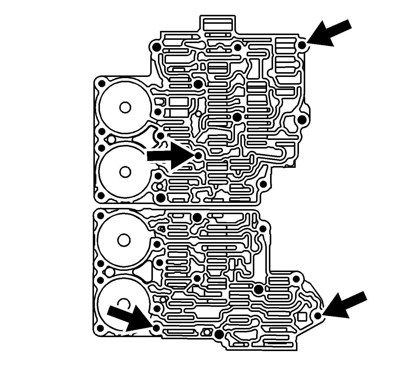
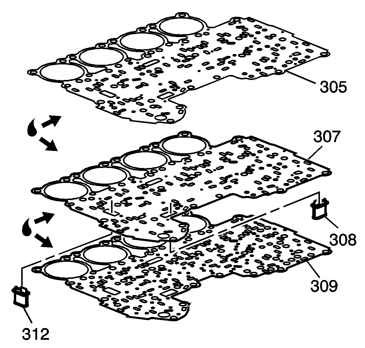
Note: Ensure the coating of transmission fluid is covering the area where the guide pins are installed.
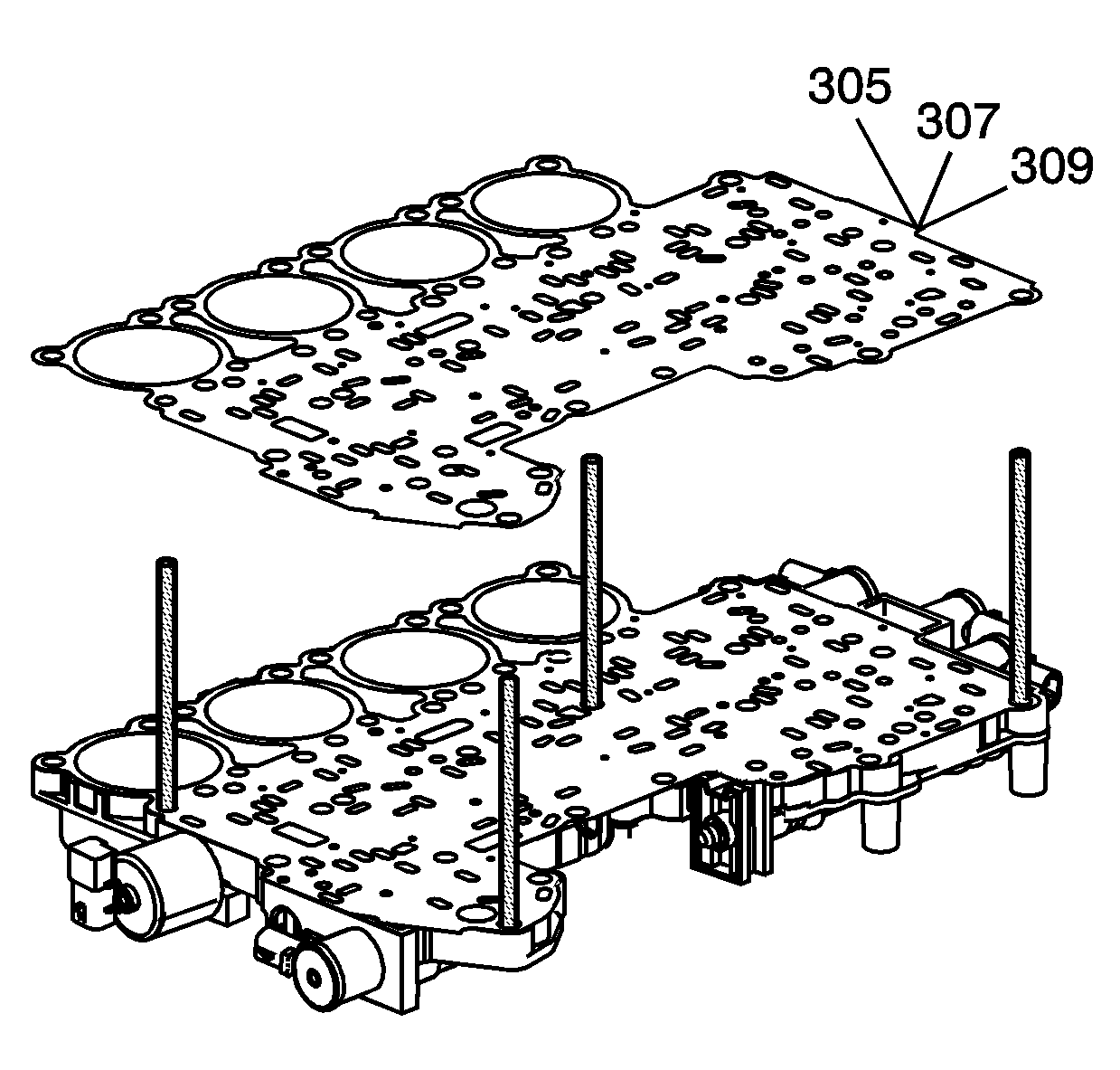
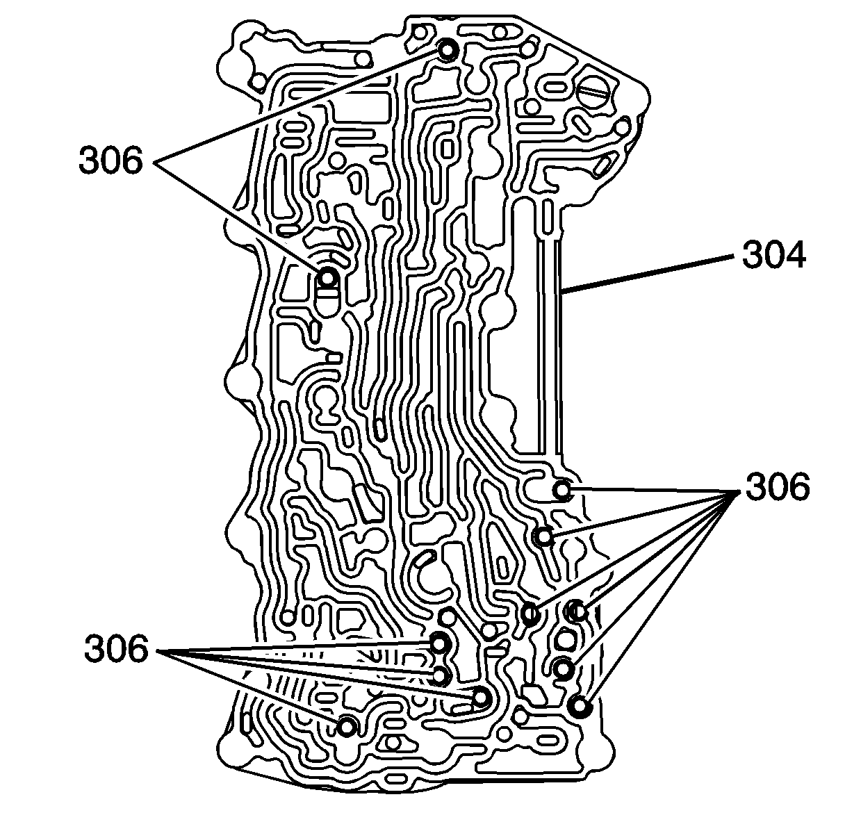
Note: Do not use an excessive amount of J 36850 lubricant to retain the checkballs.
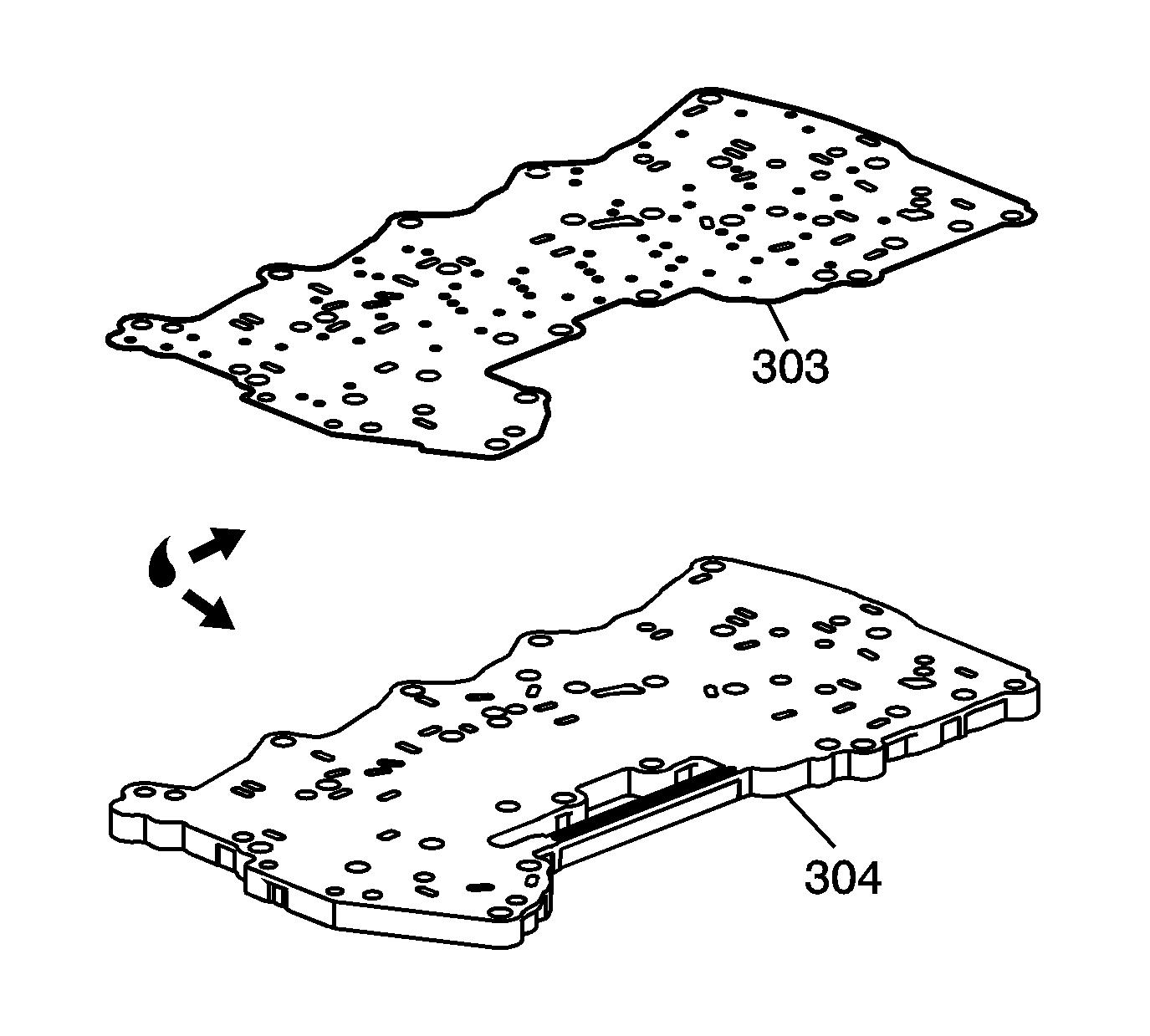
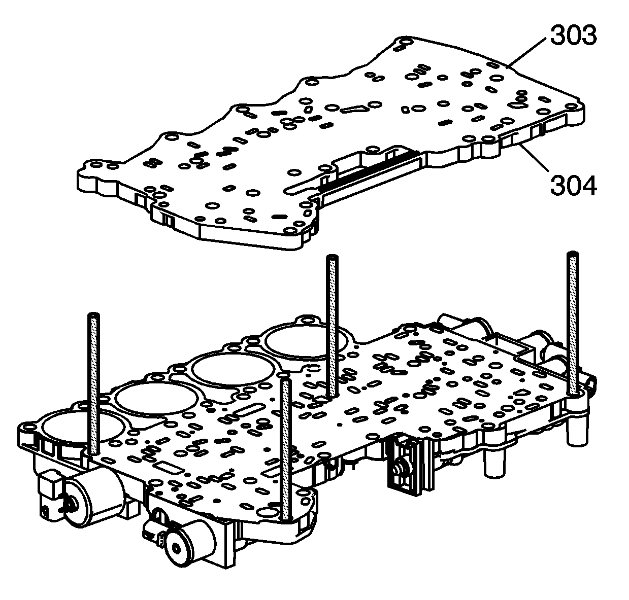
Note: The manual valve should not turn while aligning channel plate.
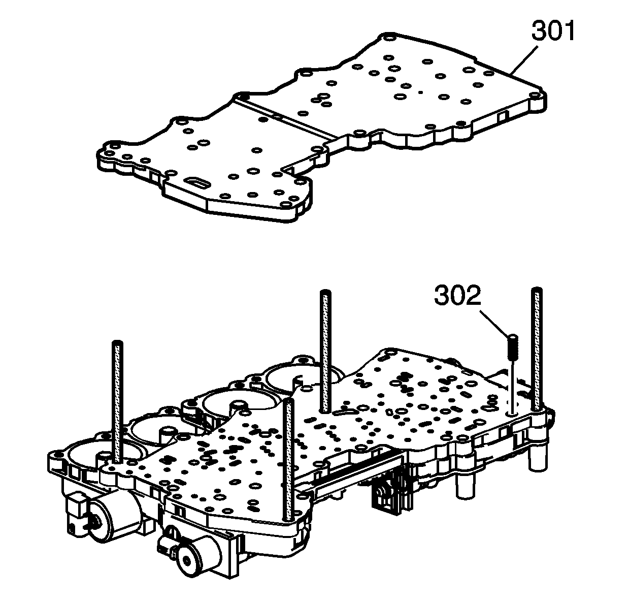
Caution: Use care not to damage the TCC check ball and spring. The spring must be centered in its hole to avoid hanging up on the spacer plate.
Caution: Refer to Fastener Caution in the Preface section.
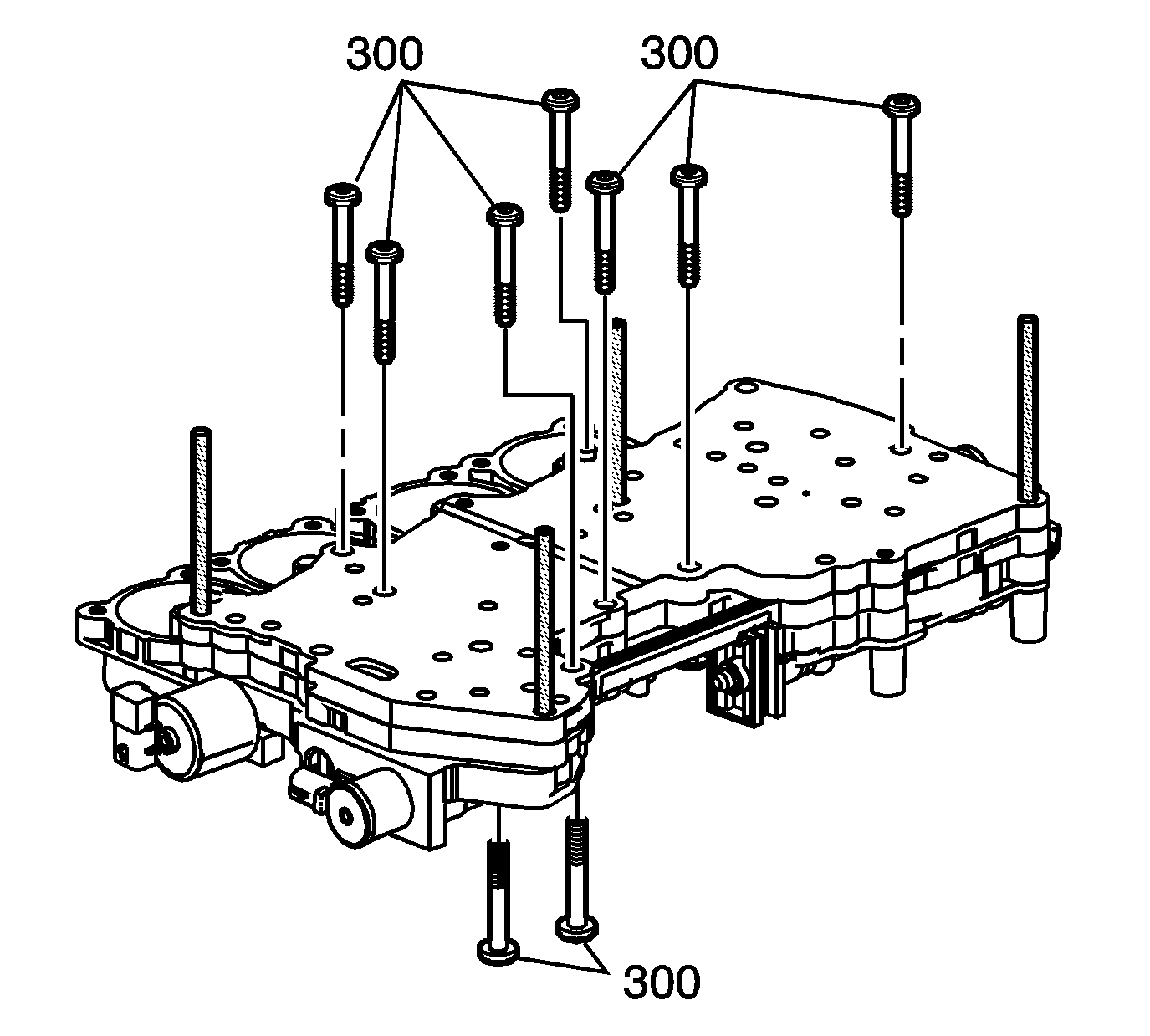
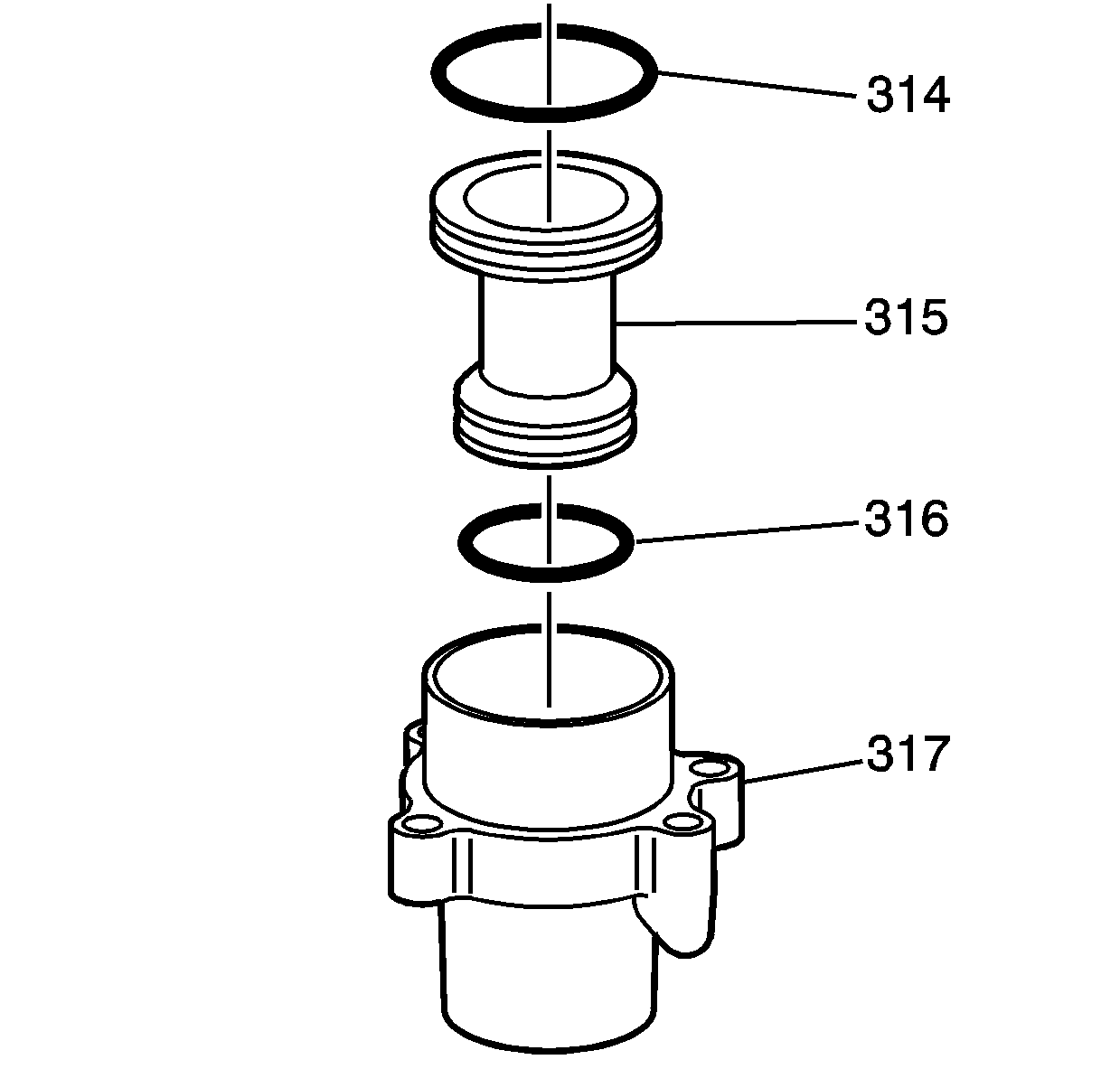
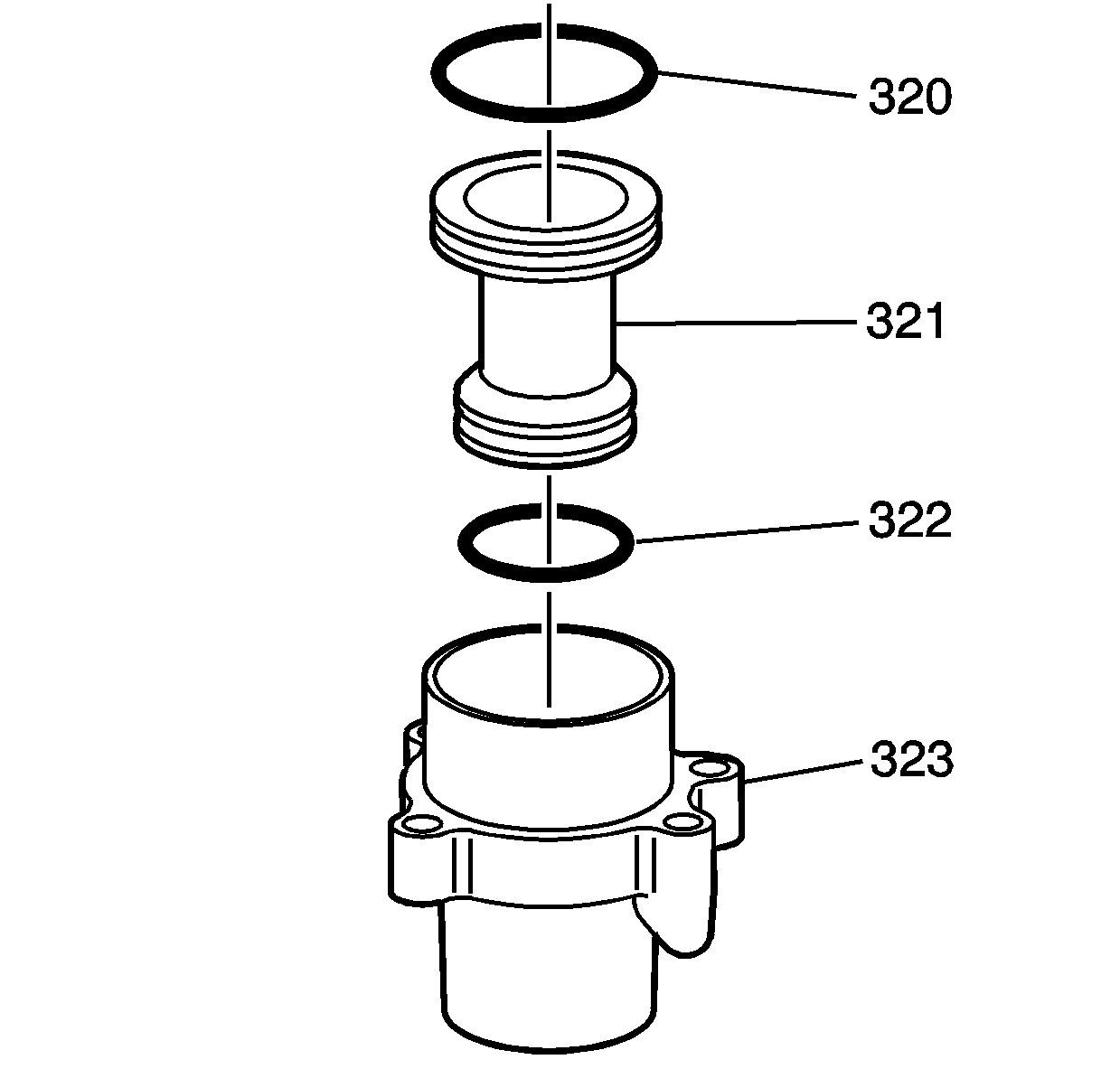
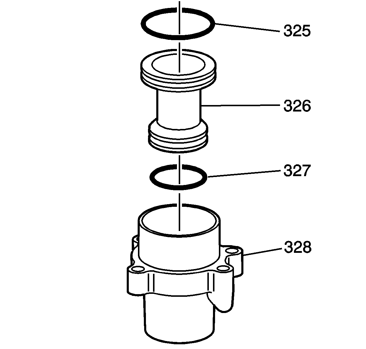
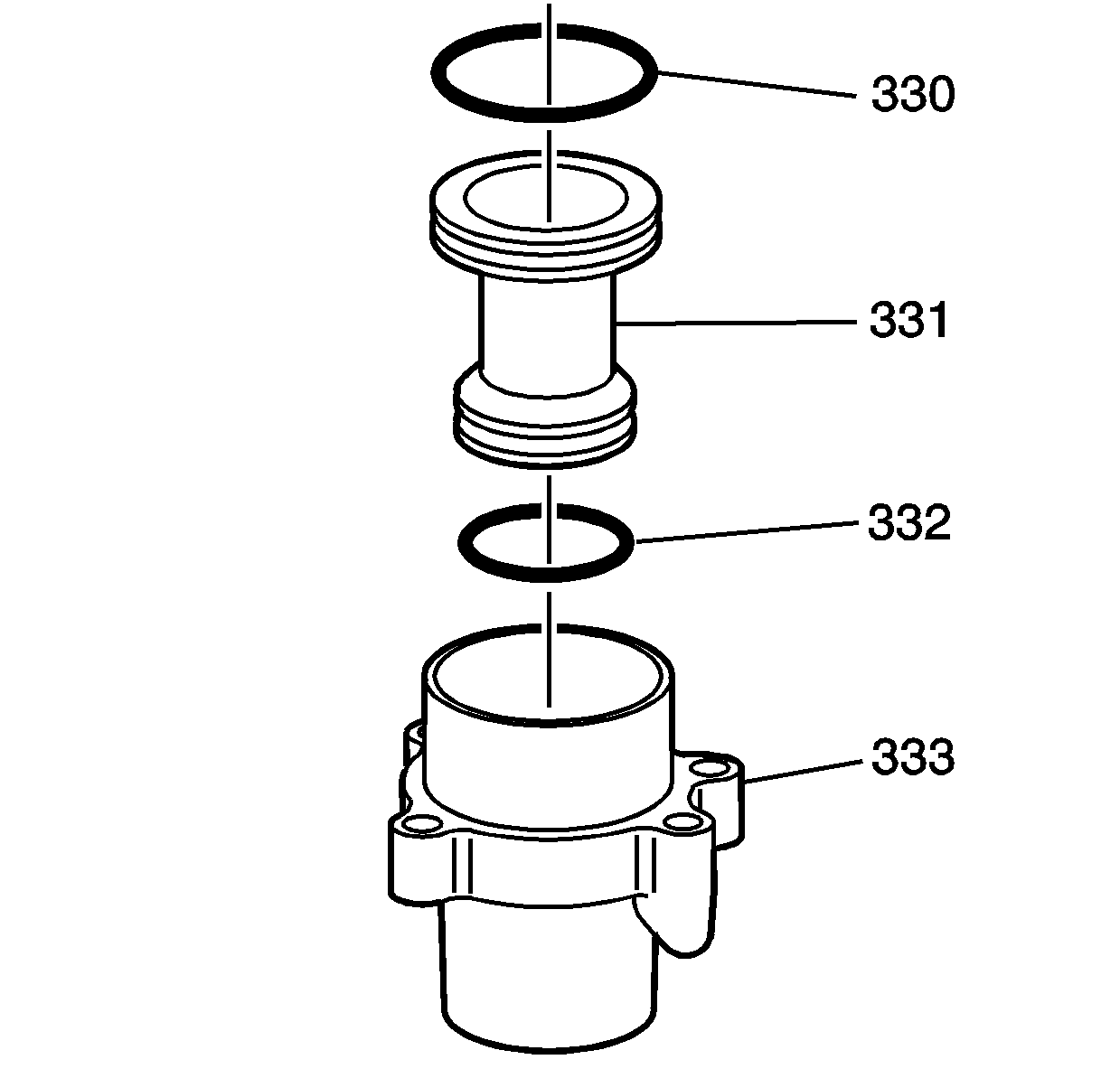
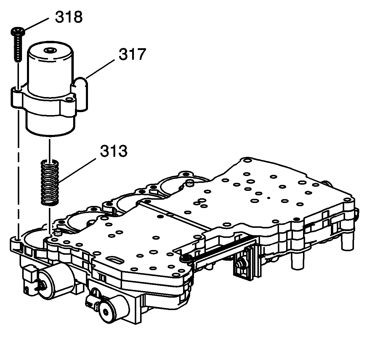
Note: Reassemble the accumulators in the position they were before disassembly. Refer to Control Valve Body Accumulator Assembly Disassemble.
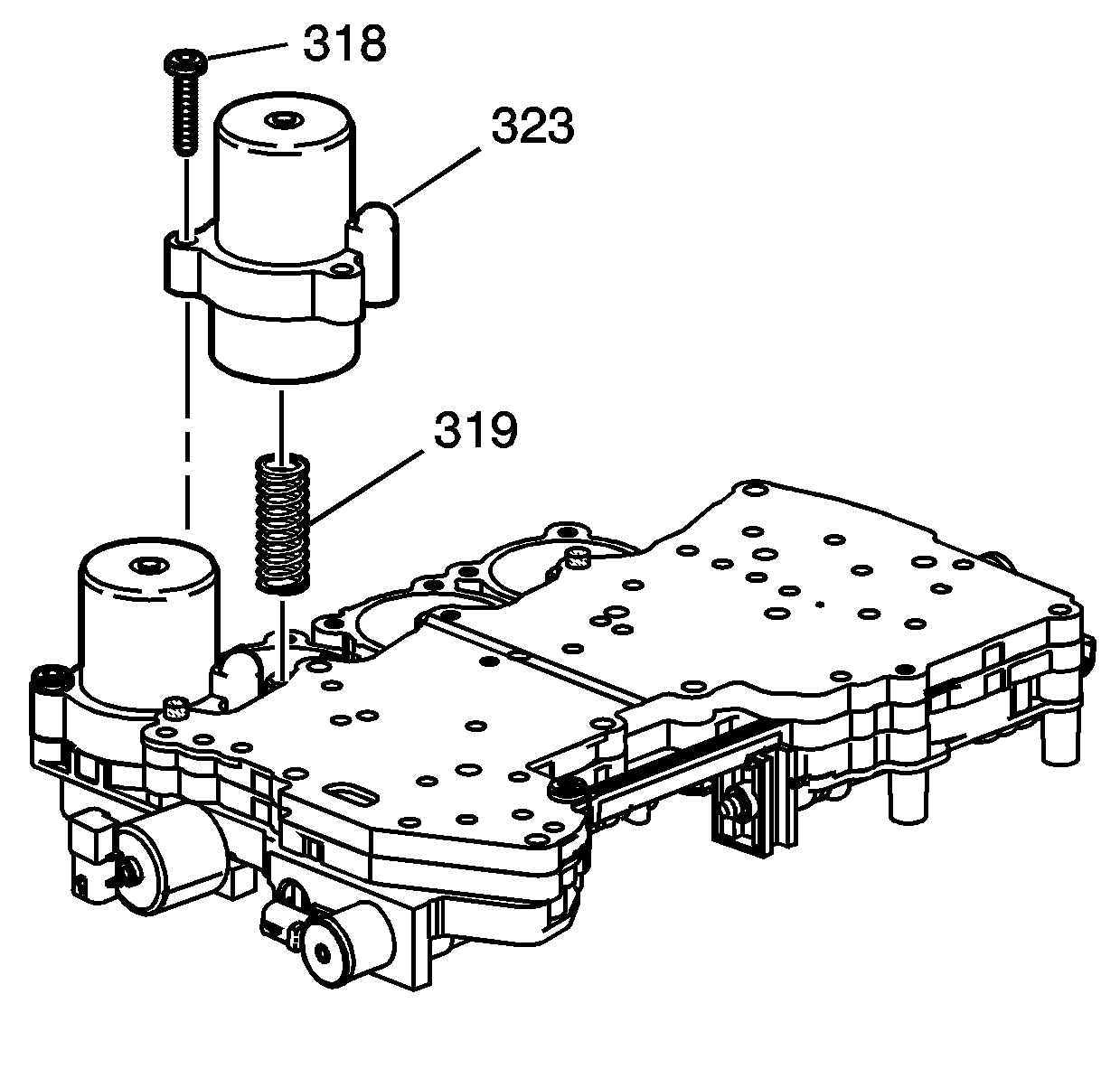
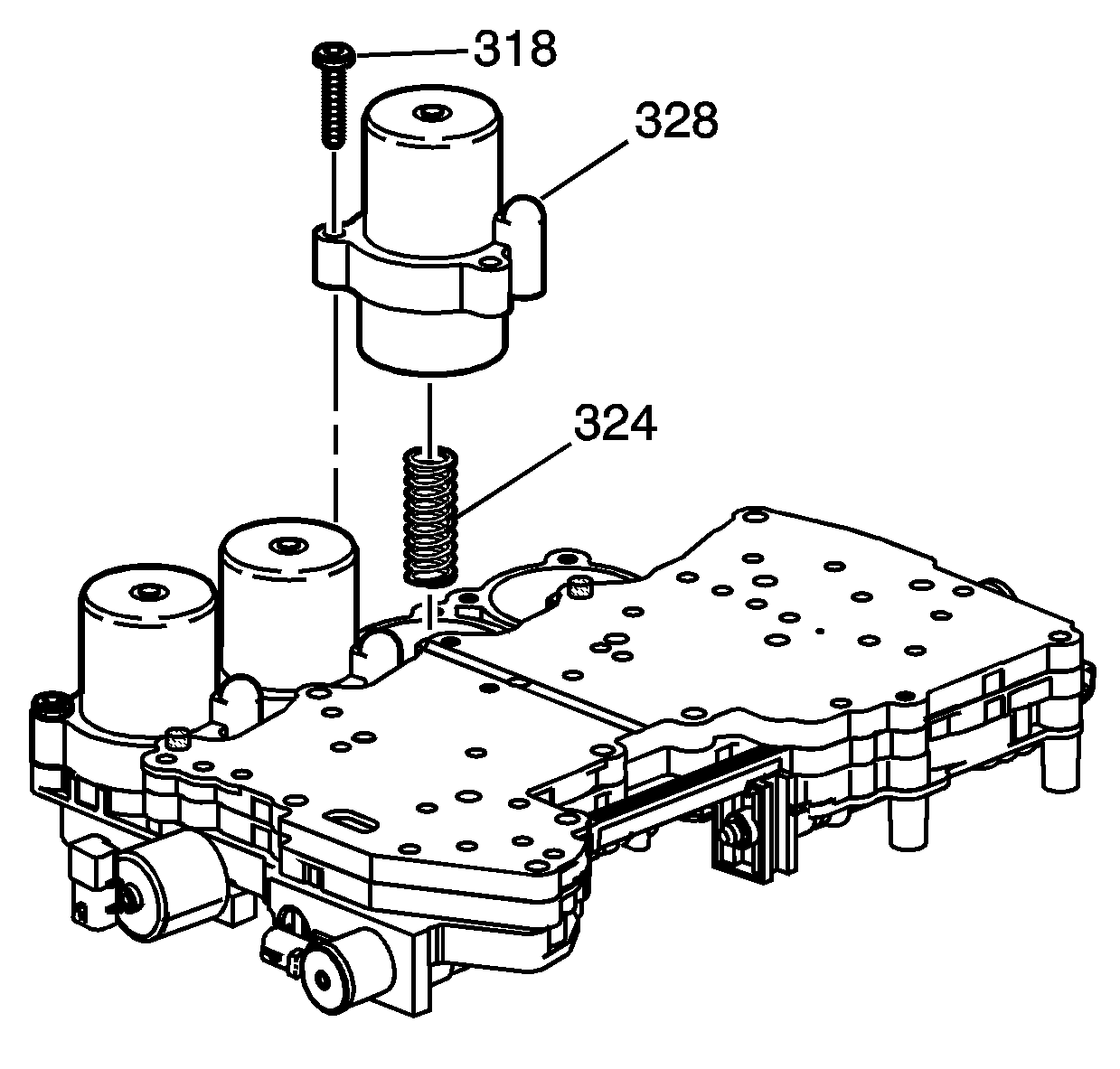
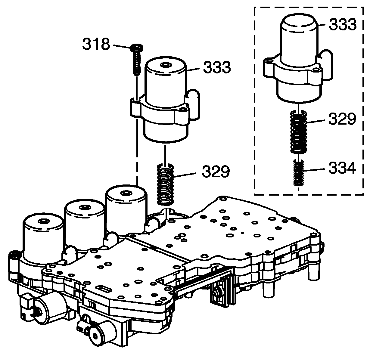
Note: The 5L50-E has a unique stackup on the 2nd clutch accumulator housing.
