Removal Procedure
Warning: Refer to Brake Fluid Irritant Warning in the Preface section.
Caution: Refer to Brake Fluid Effects on Paint and Electrical Components Caution in the Preface section.
Caution: Always connect or disconnect the wiring harness connector from the EBCM/EBTCM with the ignition switch in the OFF position. Failure to observe this precaution could result in damage to the EBCM/EBTCM.
- Turn the ignition switch to the OFF position.
- Clean the electronic brake control module (EBCM) to brake pressure modulator valve (BPMV) area of any accumulated dirt and foreign material.
- Disconnect the brake fluid level indicator switch electrical connector.
- Disconnect the vacuum brake booster vacuum sensor electrical connector.
- Release the wiring harness retainer from the master cylinder mounting stud and position the wiring harness downward.
- Remove and discard the 2 master cylinder nuts.
- If equipped, disconnect the clutch master cylinder hose from the brake master cylinder reservoir.
- Remove the 2 master cylinder brake pipe fittings from the BPMV.
- Remove the brake master cylinder and master cylinder brake pipes as an assembly.
- Remove the 2 rear brake pipe fittings (1) from the BPMV.
- Remove the 2 front brake pipe fittings (2) from the BPMV.
- Lift the locking tabs on the lower edge of the EBCM electrical connector (3) and disconnect the electrical connector.
- Position the EBCM electrical connector and the wiring harness toward the front of the vehicle.
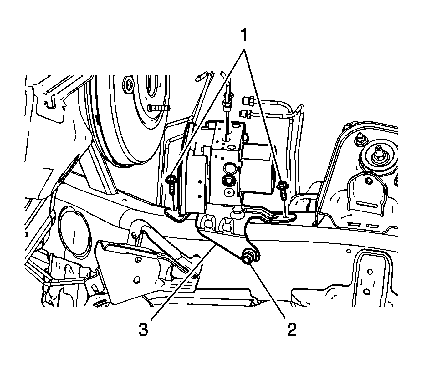
- Remove the 2 upper BPMV bracket bolts (1).
- Loosen, but do not remove the lower BPMV bracket bolt (2).
- Remove the brake modulator and bracket assembly (3).
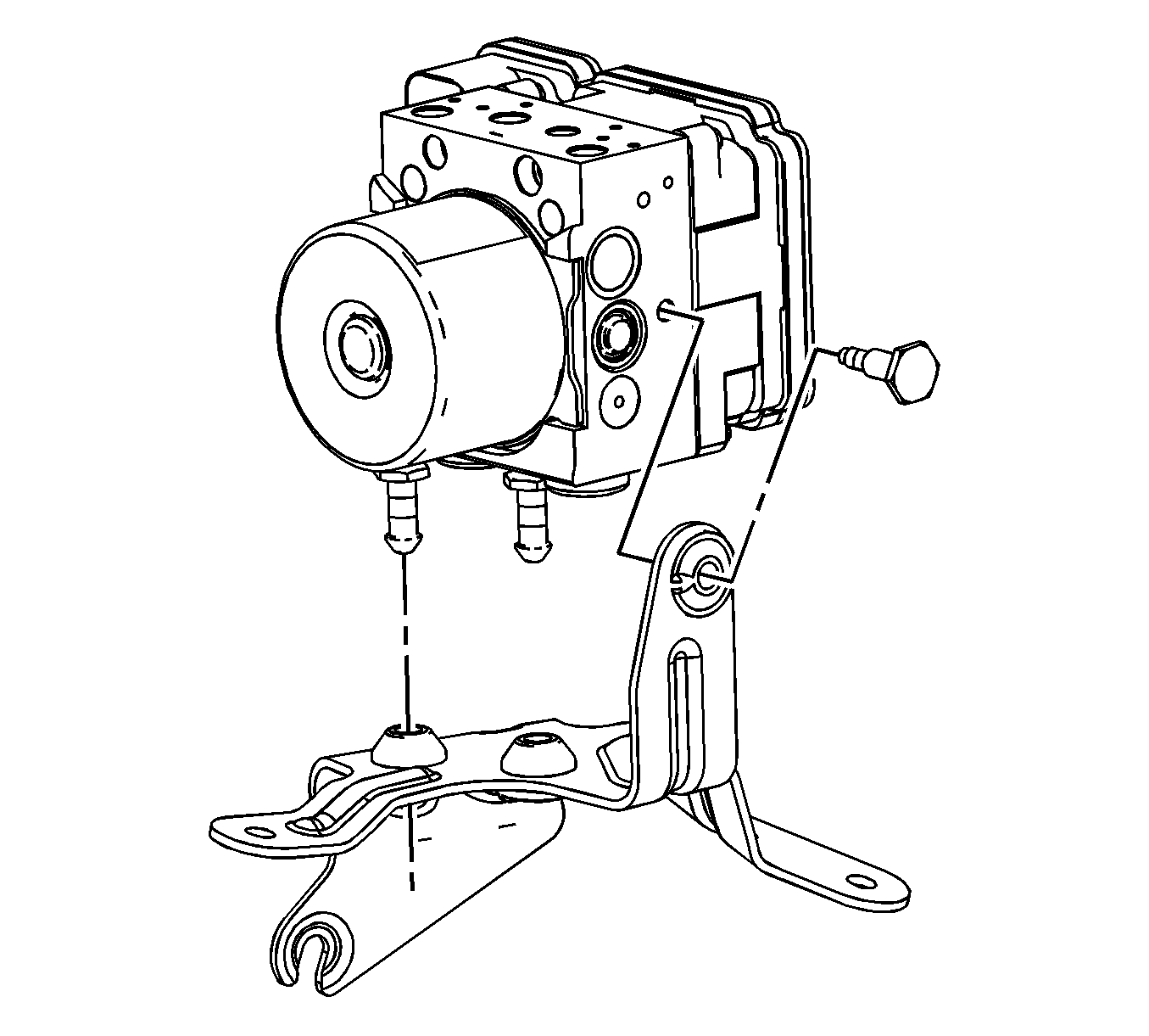
- Remove the BPMV bolt.
- Carefully separate the BPMV from the bracket. Do not pry against the accumulator covers on the underside of the BPMV.
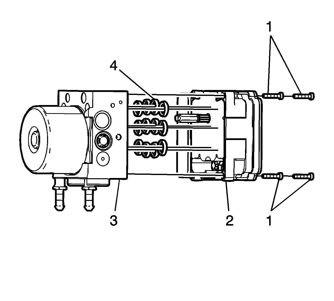
- Remove the EBCM bolts (1).
- Carefully pull the EBCM (2) from the BPMV (3). Do not pry the components apart.
- If installing a new BPMV, remove and discard the EBCM O-ring seals (4).
- If reinstalling the BPMV, clean the sealing surface of the BPMV with denatured alcohol and allow to dry.
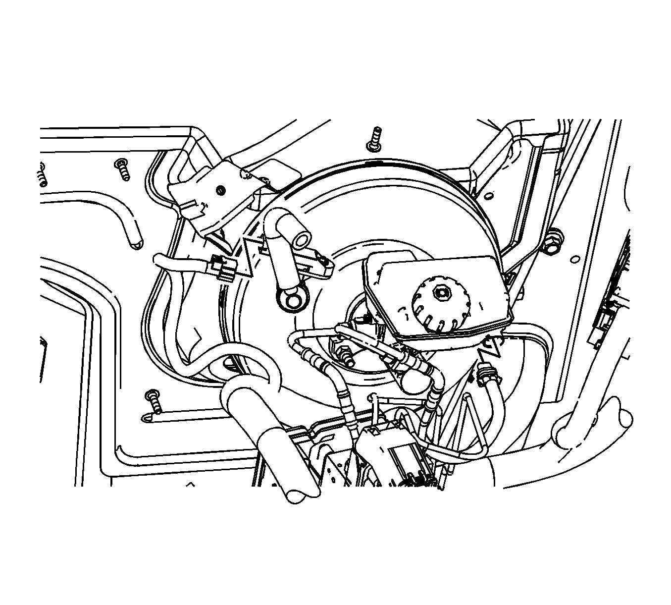
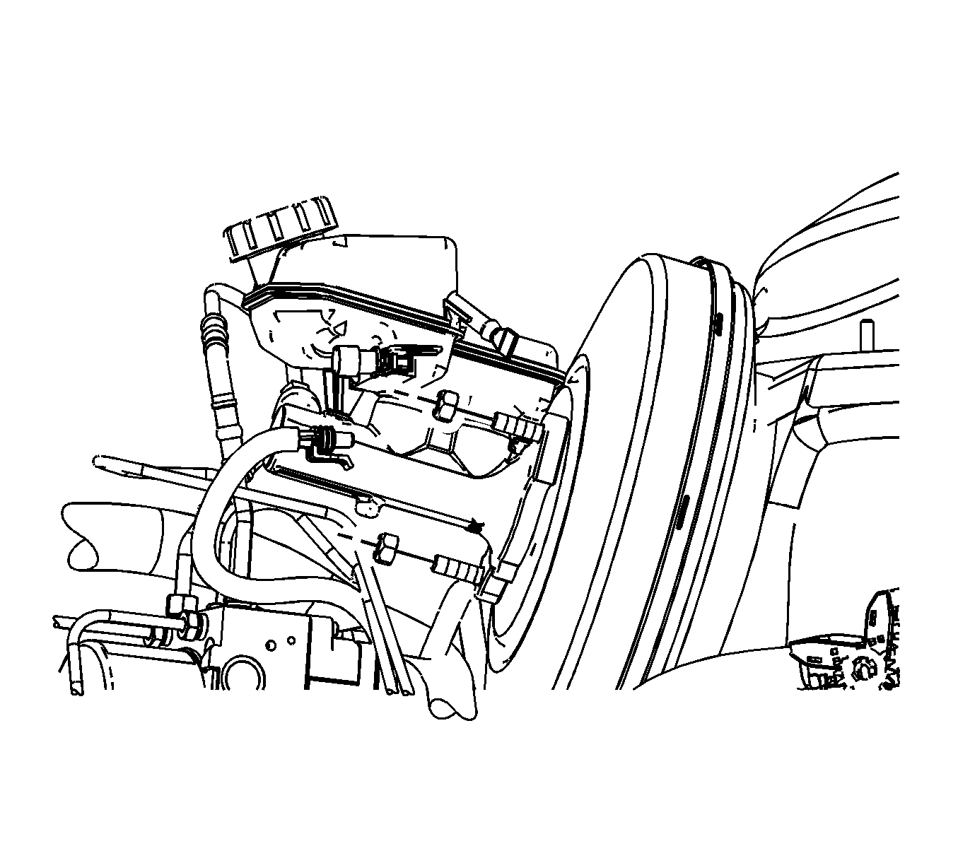
Cap the brake fluid reservoir outlet and plug the clutch master cylinder hose inlet to prevent brake fluid loss and contamination.
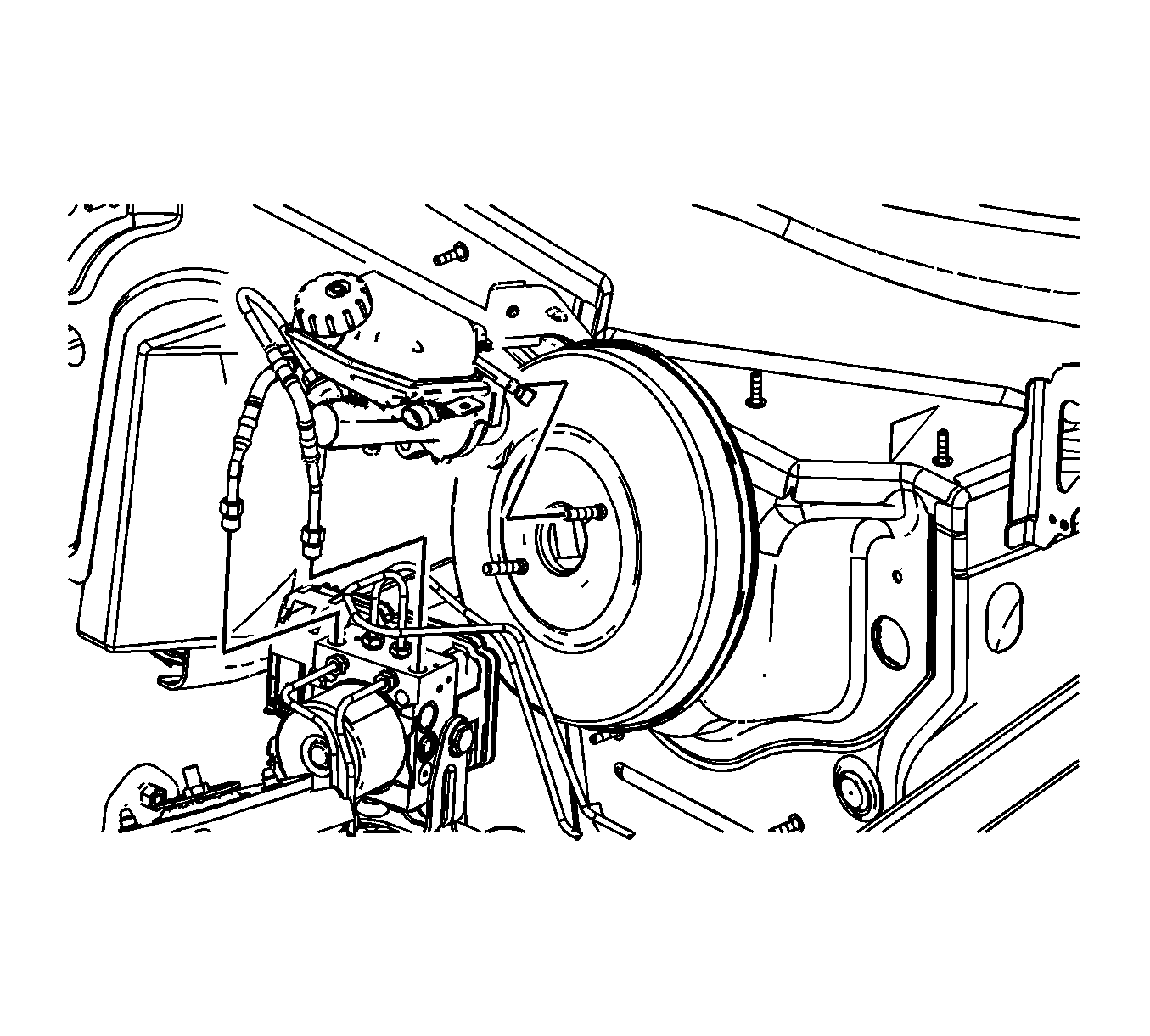
Cap the brake pipe fittings and plug the BPMV inlet ports to prevent brake fluid loss and contamination.
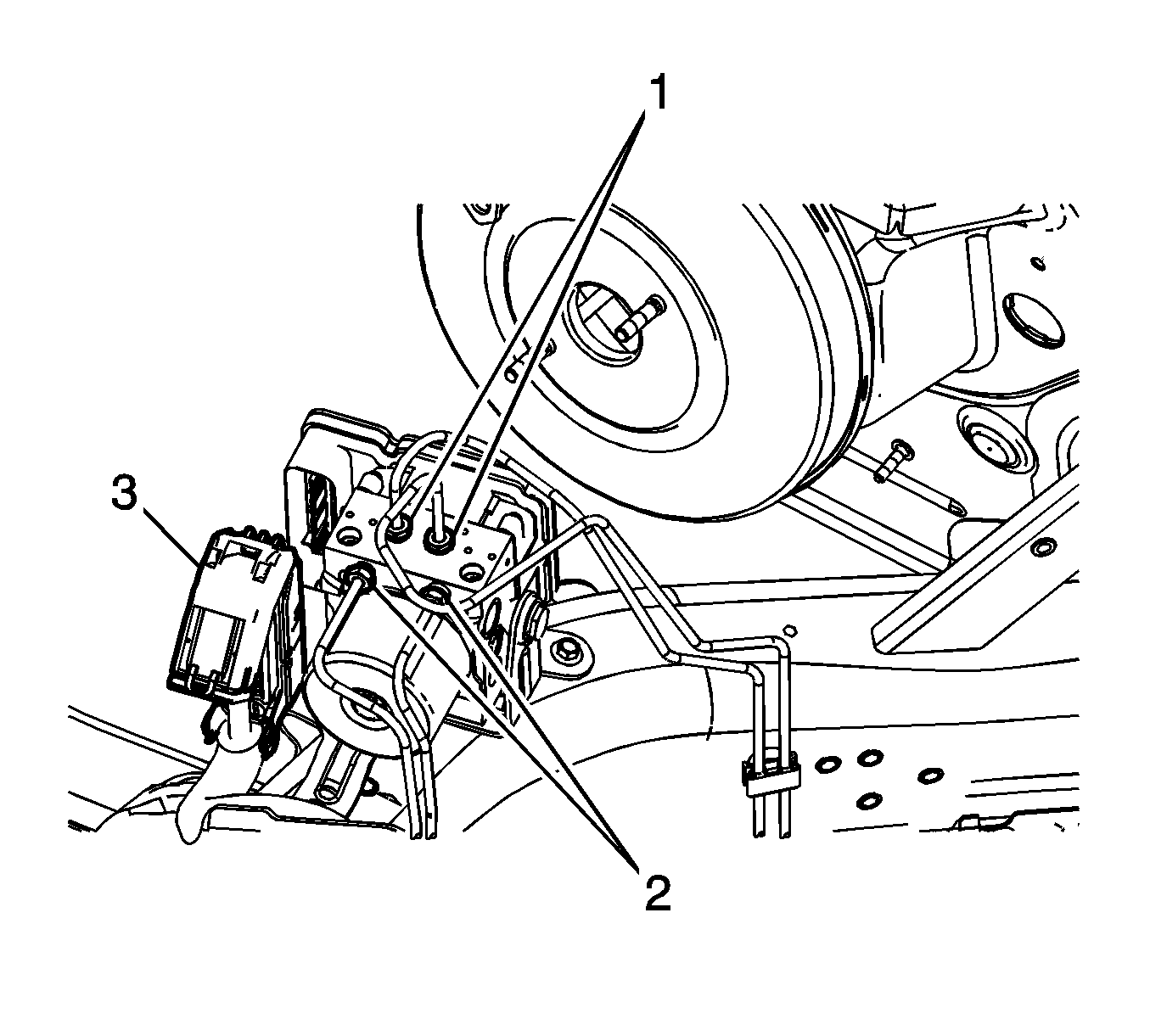
Cap the brake pipe fittings to prevent brake fluid loss and contamination.
Cap the brake pipe fittings to prevent brake fluid loss and contamination.
Installation Procedure
- If installing a new BPMV, install new EBCM O-ring seals (4) to the BPMV (3).
- Carefully install the EBCM (2) to the BPMV.
- Install the EBCM bolts (1) and tighten to 2.3 N·m (20 lb in).
- Inspect the BPMV bracket insulators for damage and replace if necessary.
- Install the BPMV to the bracket.
- Install the BPMV bolt and tighten to 11 N·m (97 lb in).
- Install the brake modulator and bracket assembly (3). Align the BPMV bracket to the lower bracket bolt (2).
- Install the 2 upper brake modulator bracket bolts (1) and tighten to 10 N·m (89 lb in).
- Install the lower brake modulator bracket bolt and tighten to 10 N·m (89 lb in).
- Install the 2 rear brake pipe fittings (1) to the BPMV and tighten to 20 N·m (15 lb ft).
- Install the 2 front brake pipe fittings (2) to the BPMV and tighten to 20 N·m (15 lb ft).
- Connect the EBCM electrical connector (3). Ensure the tabs on the cam lever are securely locked in place.
- Install the brake master cylinder and brake pipes assembly to the vacuum brake booster.
- Install the 2 master cylinder brake pipe fittings to the BPMV and tighten to 20 N·m (15 lb ft).
- If equipped, connect the clutch master cylinder hose to the brake master cylinder reservoir.
- Install 2 new brake master cylinder nuts and tighten to 20 N·m (15 lb ft).
- Position the wiring harness upward and install the wiring harness retainer to the master cylinder mounting stud on the vacuum brake booster.
- Connect the brake booster vacuum sensor electrical connector.
- Connect the brake fluid level indicator switch electrical connector.
- If a new EBCM was installed, program the EBCM. Refer to Control Module References.
- Bleed the hydraulic brake system. Refer to Hydraulic Brake System Bleeding.
- Perform the Diagnostic System Check - Vehicle.
- Observe the brake pedal feel after performing the diagnostic system check. If the pedal now feels spongy, air may have been introduced into the secondary hydraulic circuit of the brake modulator which then may have been introduced into the primary circuit. If the pedal feels spongy, perform the Antilock Brake System Automated Bleed Procedure.

Note: Ensure the brake pressure switch is properly aligned to the BPMV when installing the EBCM. Do not force the components together.
Caution: Refer to Fastener Caution in the Preface section.

Note: If necessary, a small amount of denatured alcohol can be used as an assembly aid for installing the BPMV mounting pins to the BPMV bracket.


Note: A new BPMV comes with both the primary and secondary circuits pre-filled with brake fluid. If the ignition key has not been cycled after installation, only a base brake bleed is necessary.
