Removal Procedure
- Remove the fuel injector sight shield. Refer to
Fuel Injector Sight Shield Replacement.
- Release the clamp from the brake booster vacuum hose connection.
- Disconnect the brake booster vacuum hose from the intake manifold.
- Remove the air cleaner assembly. Refer to
Air Cleaner Assembly Replacement.
- Discharge the fuel system. Refer to
Fuel Pressure Relief.
- Disconnect the evaporative emission (EVAP) hose/pipe from the EVAP canister purge solenoid valve. Refer to
Plastic Collar Quick Connect Fitting Service.
- Disconnect the engine fuel hose/pipe from the chassis fuel hose/pipe. Refer to
Metal Collar Quick Connect Fitting Service.
- Discharge the air conditioning (A/C) system. Refer to
Refrigerant Recovery and Recharging.
- Remove the A/C compressor suction hose assembly from the compressor. Cap or plug the hoses and compressor to prevent contamination. Refer to
Suction Hose Replacement.
- Remove the A/C compressor discharge hose assembly from the compressor. Cap or plug the hoses and compressor to prevent contamination. Refer to
Discharge Hose Replacement.
- Drain the engine coolant from the cooling system. Refer to
Cooling System Draining and Filling.
- Tie the radiator, A/C condenser, and fan module assembly to the upper radiator support to keep the assembly with the vehicle when the frame and drivetrain is removed.
- Remove the coolant recovery reservoir. Refer to
Coolant Recovery Reservoir Replacement.
- Disconnect the inlet coolant heater hose from the engine. Refer to
Heater Inlet Hose Replacement.
- Disconnect the outlet coolant heater hose from the engine. Refer to
Heater Outlet Hose Replacement.
- Remove the radiator inlet hose. Refer to
Radiator Inlet Hose Replacement.
- Raise and support the vehicle. Refer to
Lifting and Jacking the Vehicle.
- Remove the radiator outlet hose. Refer to
Radiator Outlet Hose Replacement.
- Remove the exhaust flexible pipe and secure the rear half of the exhaust system to the vehicle underbody. Refer to
Exhaust Flexible Pipe Replacement.
- Remove the front tires. Refer to
Tire and Wheel Removal and Installation.
- Remove the engine splash shield. Refer to
Engine Splash Shield Replacement.
- Remove the steering intermediate shaft pinch bolt and discard the bolt.
- Disconnect the steering intermediate shaft from the steering gear.
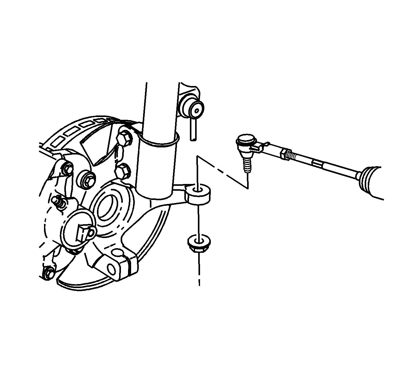
- Remove the right and left steering linkage outer tie rod ends from the steering knuckles. Refer to
Steering Linkage Outer Tie Rod Replacement.
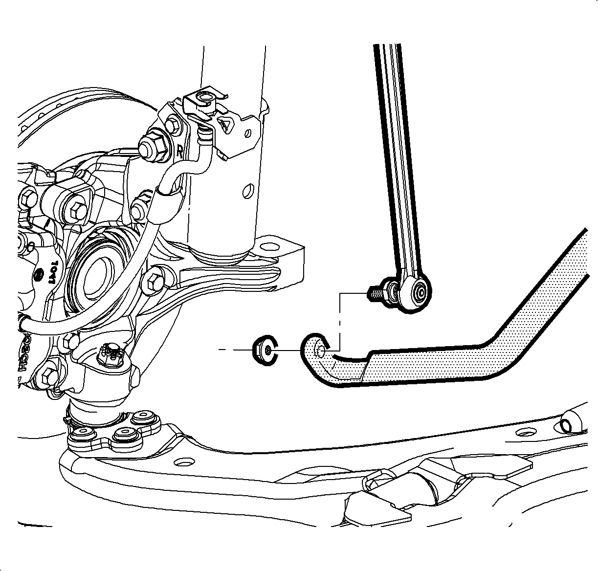
- Remove the right and left stabilizer shaft links from the stabilizer shaft. Refer to
Stabilizer Shaft Link Replacement.
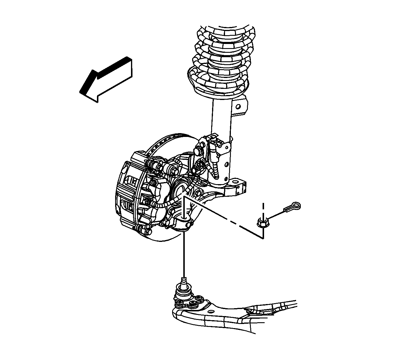
- Remove the right and left lower ball joints from the steering knuckles. Refer to
Lower Control Arm Replacement.
- On front wheel drive (FWD) models, place a drain pan under the transaxle then separate the right and left front wheel drive shafts from the transaxle. Refer to
Front Wheel Drive Shaft Replacement.
- On all wheel drive (AWD) models, remove the driveline torque tube. Refer to
Driveline Torque Tube Replacement.
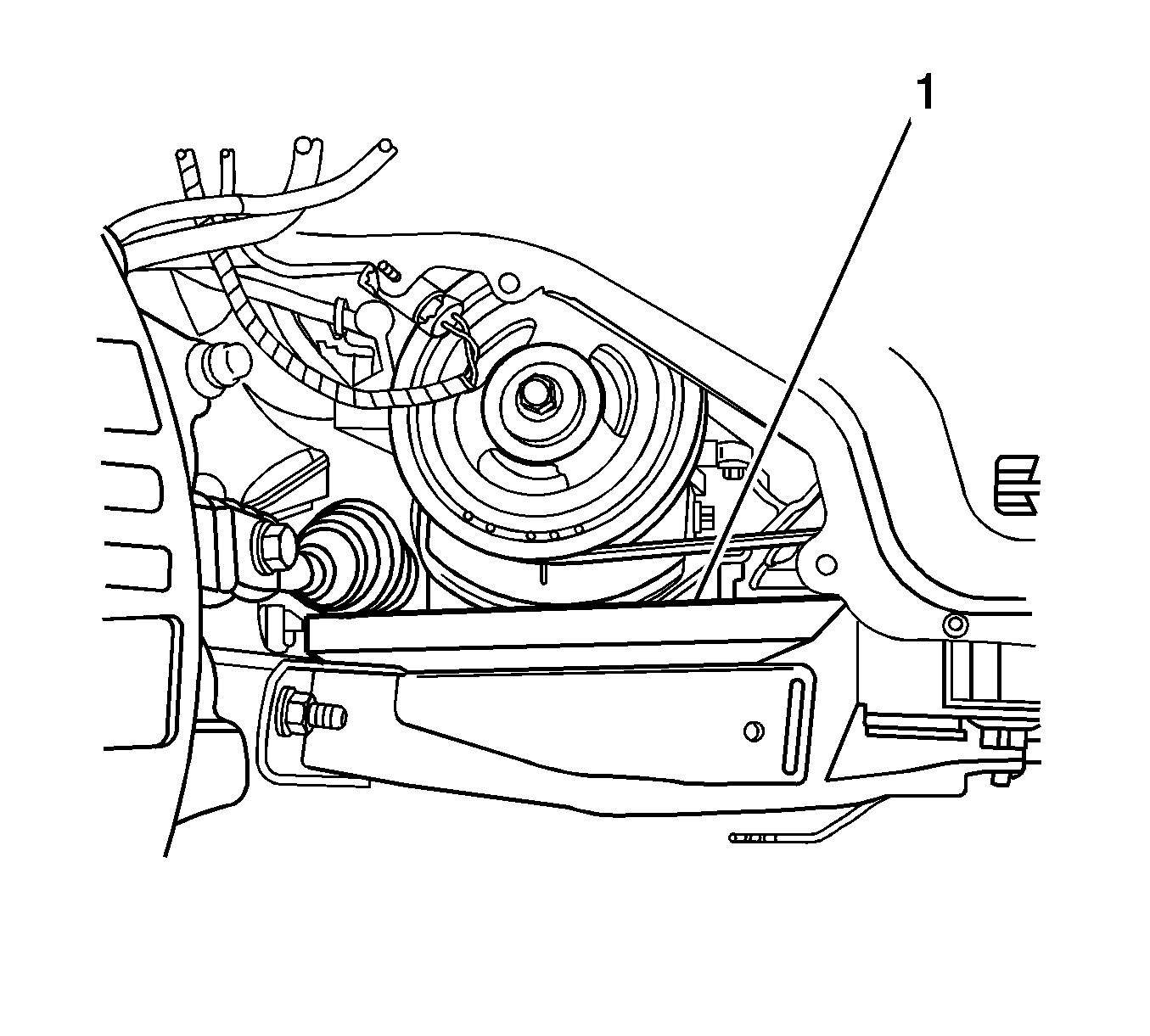
- On all models, place a block of wood (1) between the frame and the engine oil pan in order to support
the engine once the bolts are removed from the right engine mount.
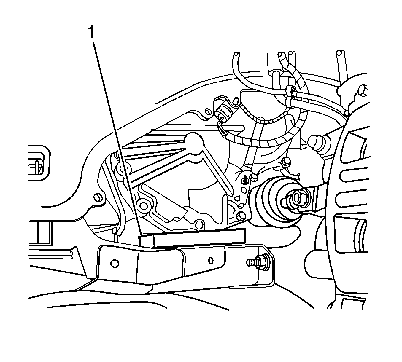
- Place a block of wood (1) between the frame and the transaxle in order
to support the transaxle once the bolts are removed from the left transaxle mount bracket.
- Lower the vehicle.
- Remove the engine mount strut. Refer to
Engine Mount Strut Replacement - Right Side.
- Remove the left transaxle mount bracket. Refer to
Transmission Mount Bracket Replacement - Left Side.
Important: Insure the vehicle body is secured to the hoist.
- Raise the vehicle.
- Disconnect the power steering hoses at the power steering fluid cooler. Refer to
Power Steering Cooler Pipe/Hose Replacement.
- Place a universal frame support fixture or jackstands under the frame.
- Lower the vehicle until the frame contacts the frame support fixture or jackstands.
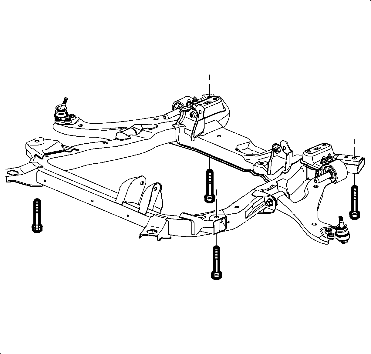
- Remove the frame-to-body bolts. Discard the bolts.
Important: Inspect for areas of body to powertrain contact or entanglement of wires and hoses while separating the vehicle body and powertrain.
- Carefully raise the vehicle body up away from the powertrain.
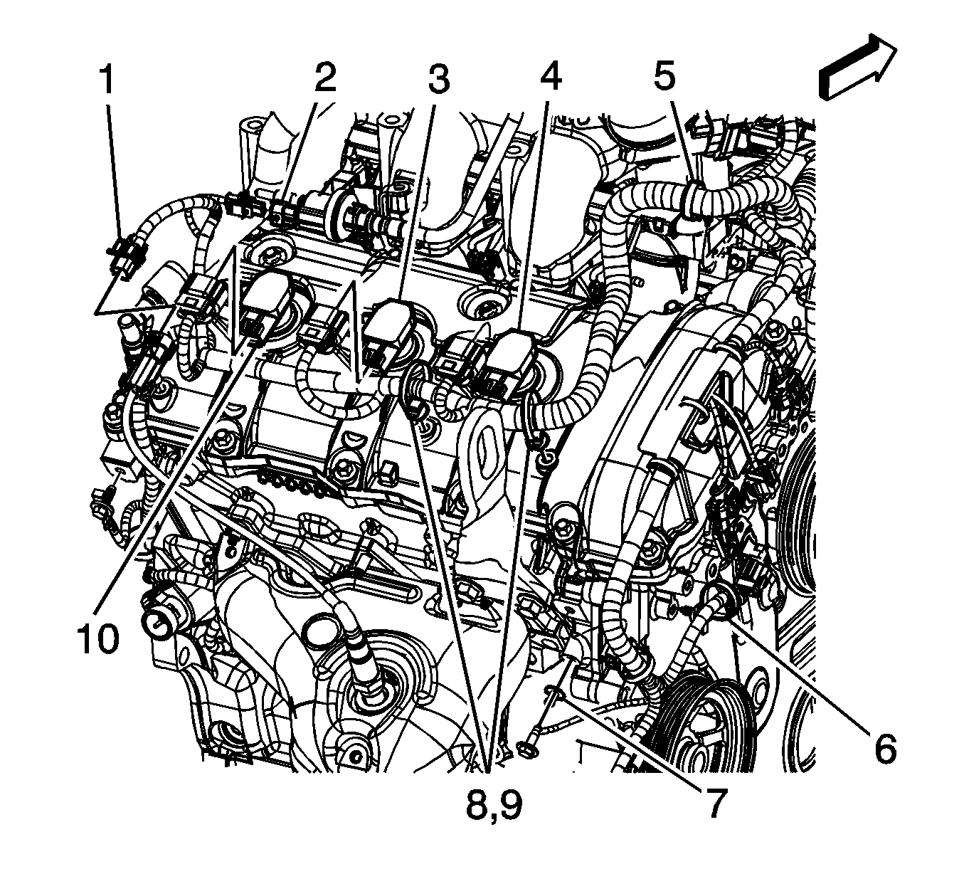
- Disconnect the engine electrical wiring harness from the following components:
| • | EVAP purge solenoid (2) |
| • | Ignition coils (3, 4, 10) |
| • | Remove wire harness from retainers (5, 6, 8, 9) |
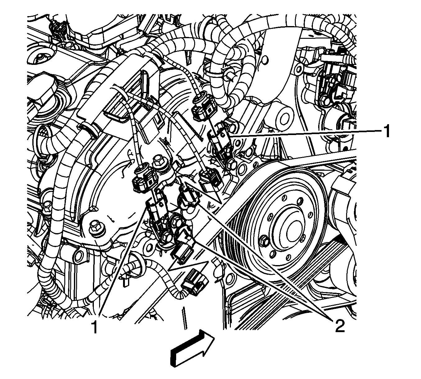
- Disconnect the left and right cylinder head engine electrical wiring harness from the following components:
| • | Camshaft position sensors (1) |
| • | Camshaft position actuators (2) |
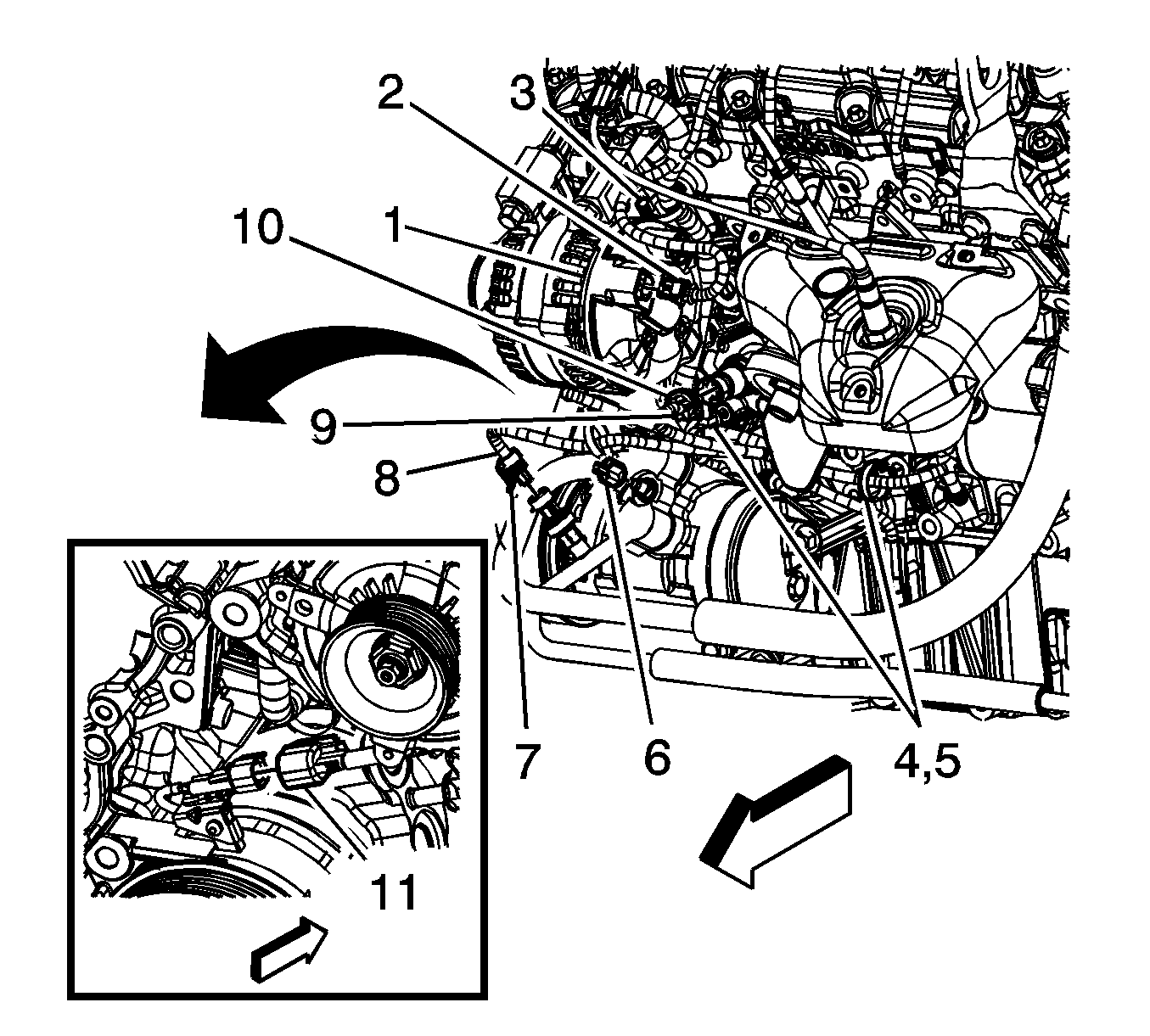
- Disconnect the engine electrical wiring harness from the following components:
| • | Retainer clips (2, 3, 4, 5, 6, 7, 9) |
| • | A/C compressor hose (8) |
| • | Oil pressure switch (10) |
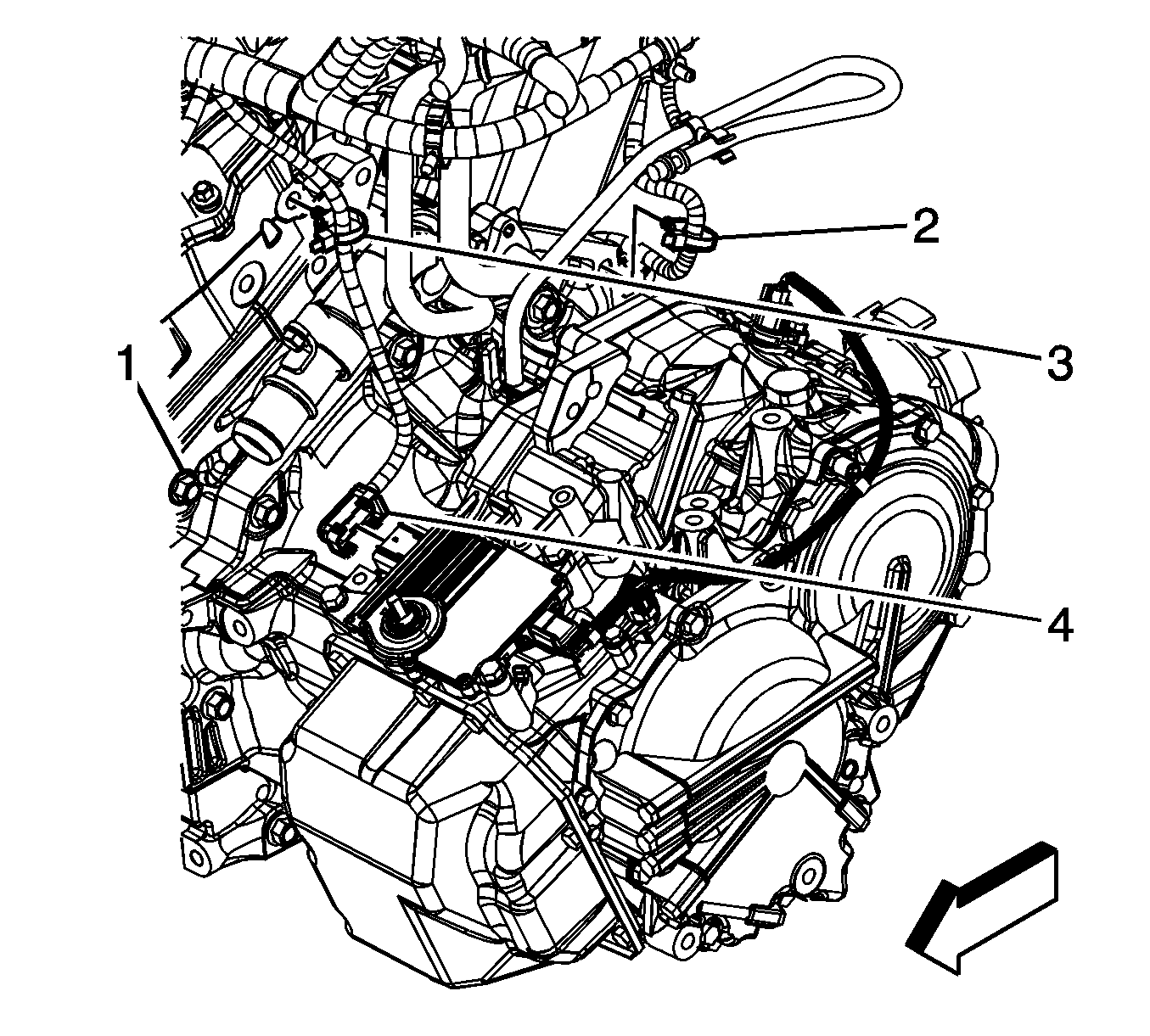
- Disconnect the engine electrical wiring harness from the following components:
| • | Transmission module (4) |
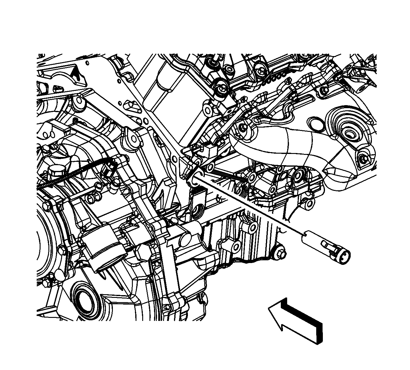
- If equipped with an engine coolant heater, disconnect the coolant heater cord.
- Remove the throttle body assembly. Refer to
Throttle Body Assembly Replacement.
- Remove the engine-to-transaxle brace bolts and brace.
- Remove the starter motor. Refer to
Starter Motor Replacement.
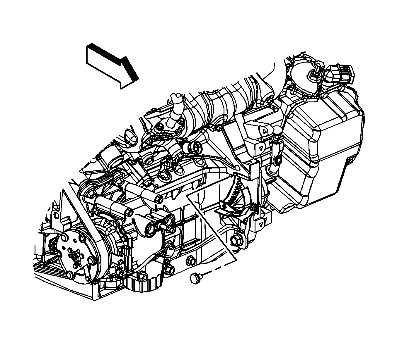
- Remove the torque converter bolts.
- Install an engine lift chain to the engine lift brackets.
- Support the engine weight with an engine hoist.
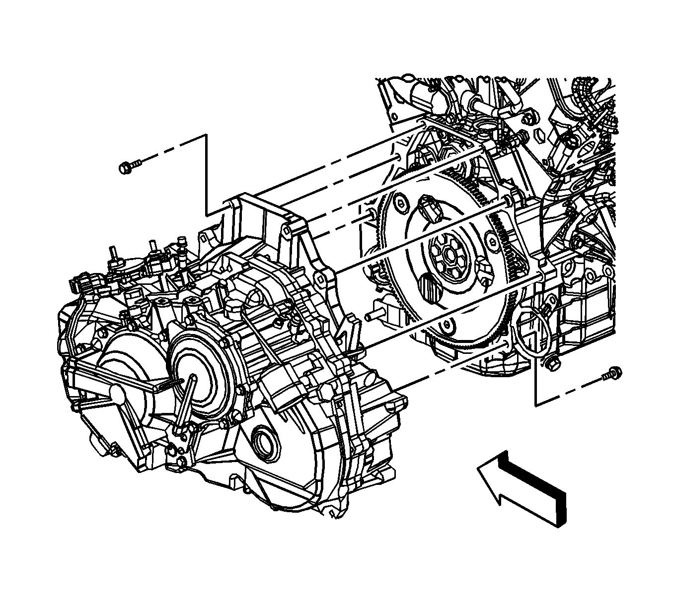
- Remove the automatic transaxle bolts.
- Separate the automatic transaxle from the engine.
- Lift the engine away from the frame and the automatic transaxle.
- Secure the engine to an engine stand.
- Remove any additional engine components as necessary. Refer to appropriate component sections in manual if needed.
Installation Procedure
- Remove the engine from the engine stand.

- Align the engine to the frame and automatic transaxle.
Notice: Refer to Fastener Notice in the Preface section.
- Install the automatic transaxle bolts.
Tighten
Tighten the bolts to 75 N·m (55 lb ft).
- Place a block of wood between the frame and the engine oil pan in order to support the engine on the frame once the engine hoist is removed.
- Remove the engine hoist and lift chain.

- Install the torque converter bolts.
Tighten
Tighten the bolts to 60 N·m (44 lb ft).
- Install the starter motor. Refer to
Starter Motor Replacement.
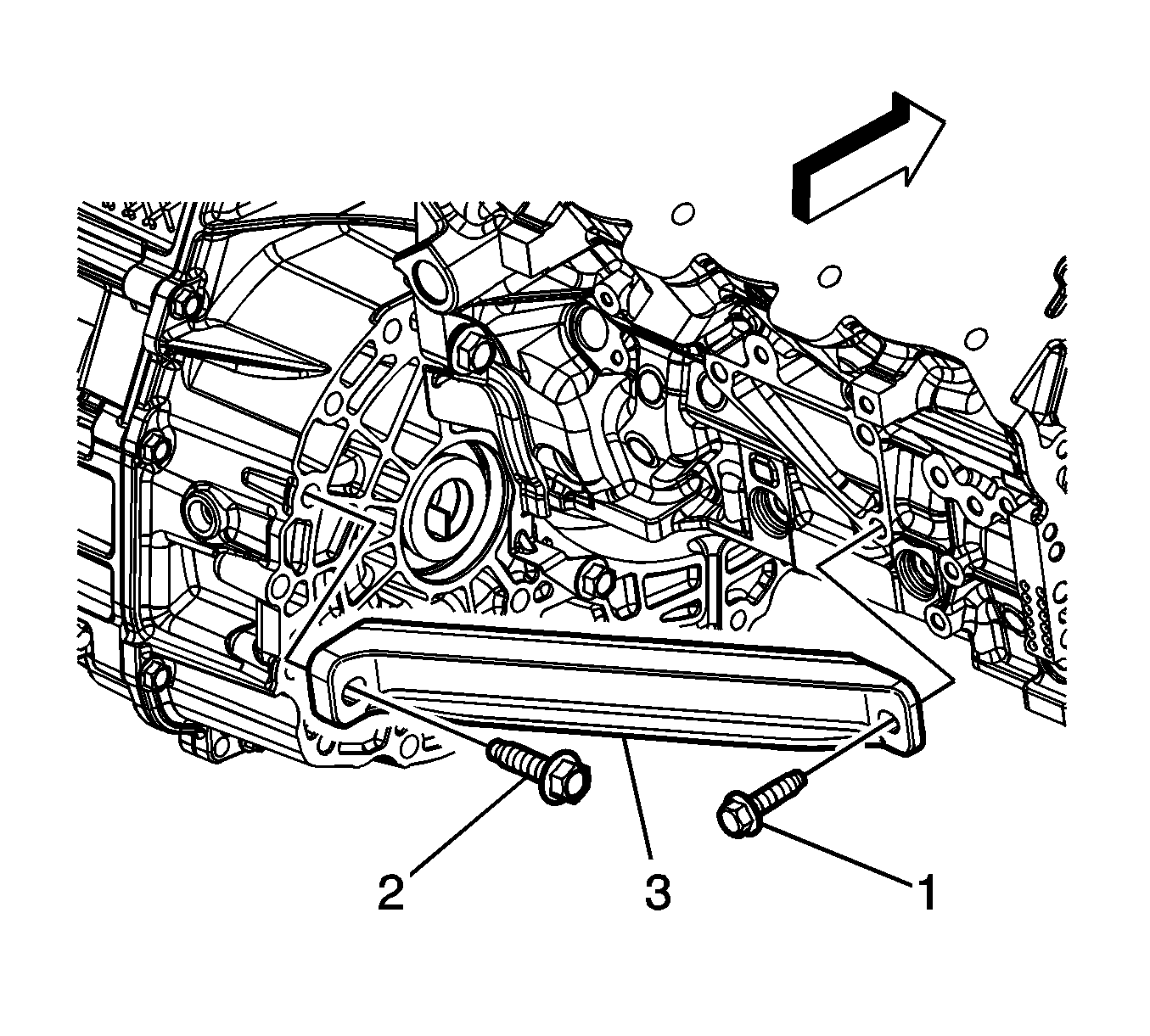
- Install the engine to transaxle brace (3) and bolts (1, 2).
Tighten
Tighten the bolts to 50 N·m (37 lb ft).
- Install the throttle body assembly. Refer to
Throttle Body Assembly Replacement.

- If equipped with an engine coolant heater, connect the coolant heater cord.

- Connect the engine electrical wiring harness to the following components:
| • | Transmission module (4) |
Tighten
Tighten the bolt to 25 N·m (18 lb ft).

- Connect the engine electrical wiring harness to the following components:
| • | Oil pressure switch (10) |
| • | A/C compressor hose (8) |
| • | Retainer clips (2, 3, 4, 5, 6, 7, 9) |
Tighten
Tighten the nut to 13 N·m (115 lb in).

- Connect the left and right cylinder head engine electrical wiring harness to the following components:
| • | Camshaft position actuators (2) |
| • | Camshaft position sensors (1) |

- Connect the engine electrical wiring harness to the following components:
| • | Install wire harness to retainers (5, 6, 8, 9) |
| • | Ignition coils (3, 4, 10) |
| • | EVAP purge solenoid (2) |

- Install NEW frame-to-body bolts.
Tighten
Tighten the bolts to 155 N·m (114 lb ft).
- Raise the vehicle up away from the frame support fixture or jackstands and remove the support fixture or jackstands from under the vehicle.
- Connect the power steering hoses to the power steering fluid cooler. Refer to
Power Steering Cooler Pipe/Hose Replacement.
- Lower the vehicle.
- Install the left transaxle mount bracket. Refer to
Transmission Mount Bracket Replacement - Left Side.
- Install the engine mount strut. Refer to
Engine Mount Strut Replacement - Right Side.
- Raise the vehicle.

- Remove the block of wood (1) between the frame and the transaxle used to
support the transaxle while the bolts were removed from the left transaxle mount bracket.

- Remove the block of wood (1) between the frame and the engine oil pan used to support the engine while
the bolts were removed from the right engine mount.
- On AWD models, Install the driveline torque tube. Refer to
Driveline Torque Tube Replacement.
- On FWD models, install the right and left front wheel drive shafts into the transaxle. Refer to
Front Wheel Drive Shaft Replacement.

- On all models, install the right and left lower ball joints to the steering knuckles. Refer to
Lower Control Arm Replacement.

- Install the right and left stabilizer shaft links to the stabilizer shaft. Refer to
Stabilizer Shaft Link Replacement.

- Install the right and left steering linkage outer tie rod ends to the steering knuckles. Refer to
Steering Linkage Outer Tie Rod Replacement.
- Connect the steering intermediate shaft to the steering gear.
- Install a NEW pinch bolt to the steering intermediate shaft.
Tighten
Tighten the bolt to 34 N·m (25 lb ft).
- Install the engine splash shield. Refer to
Engine Splash Shield Replacement.
- Install the front tires. Refer to
Tire and Wheel Removal and Installation.
- Install the exhaust flexible pipe. Refer to
Exhaust Flexible Pipe Replacement.
- Install the radiator outlet hose. Refer to
Radiator Outlet Hose Replacement.
- Lower the vehicle.
- Install the radiator inlet hose. Refer to
Radiator Inlet Hose Replacement.
- Connect the outlet coolant heater hose to the engine. Refer to
Heater Outlet Hose Replacement.
- Connect the inlet coolant heater hose to the engine. Refer to
Heater Inlet Hose Replacement.
- Install the coolant recovery reservoir. Refer to
Coolant Recovery Reservoir Replacement.
- Untie the radiator, AC condenser, and fan module assembly from the upper radiator support.
- Install the A/C compressor discharge hose assembly to the compressor. Refer to
Discharge Hose Replacement.
- Install the A/C compressor suction hose assembly to the compressor. Refer to
Suction Hose Replacement.
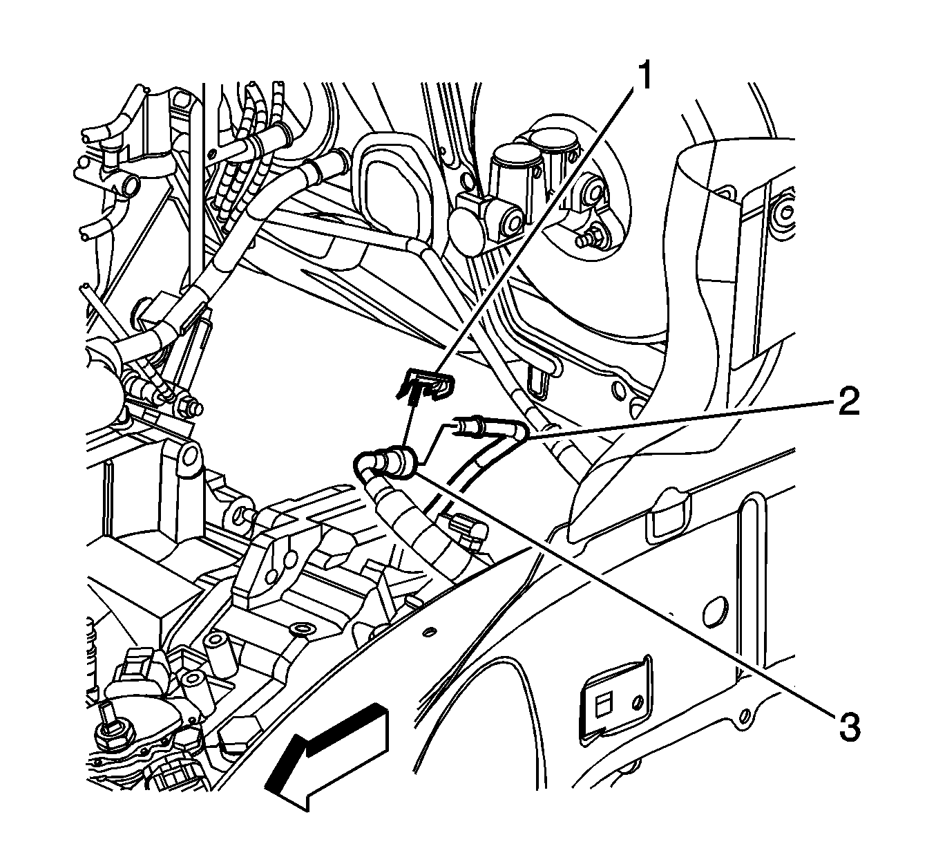
- Connect the engine fuel hose/pipe (3) to the chassis fuel hose/pipe (2). Refer to
Metal Collar Quick Connect Fitting Service.
- Connect the EVAP hose/pipe to the EVAP canister purge solenoid valve. Refer to
Plastic Collar Quick Connect Fitting Service.
- Install the air cleaner assembly. Refer to
Air Cleaner Assembly Replacement.
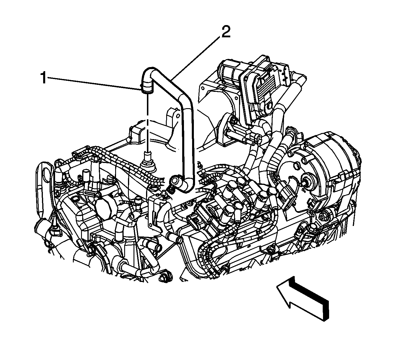
- Connect the brake booster vacuum hose (2) to the intake manifold.
- Position the clamp (1) on the brake booster vacuum hose connection.
- Install the fuel injector sight shield. Refer to
Fuel Injector Sight Shield Replacement.
- Fill the engine with engine oil. Refer to
Approximate Fluid Capacities ,
Fluid and Lubricant Recommendations , and
Maintenance Schedule.
- Fill the engine with coolant. Refer to
Cooling System Draining and Filling.
- Check the transaxle fluid level. Refer to
Adhesives, Fluids, Lubricants, and Sealers ,
Transmission General Specifications , and
Approximate Fluid Capacities.
- Charge the AC system. Refer to
Refrigerant Recovery and Recharging.
- Add power steering fluid and bleed air from the power steering system. Refer to
Power Steering System Bleeding.
- Prime the fuel system.
| 54.1. | Cycle the ignition ON for 5 seconds then OFF for 10 seconds. Repeat cycling twice. |
| 54.2. | Crank the engine until it starts. The maximum starter motor cranking time is 20 seconds. |
| 54.3. | If the engine does not start, repeat the steps. |


