- Remove the bolt and the speedometer driven hole cover.
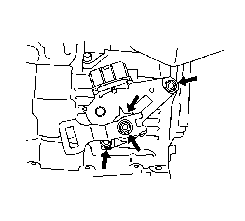
- Remove the nut, washer and control shift lever from the transaxle.
- Pry up the lock tab on the washer, then remove the retaining nut.
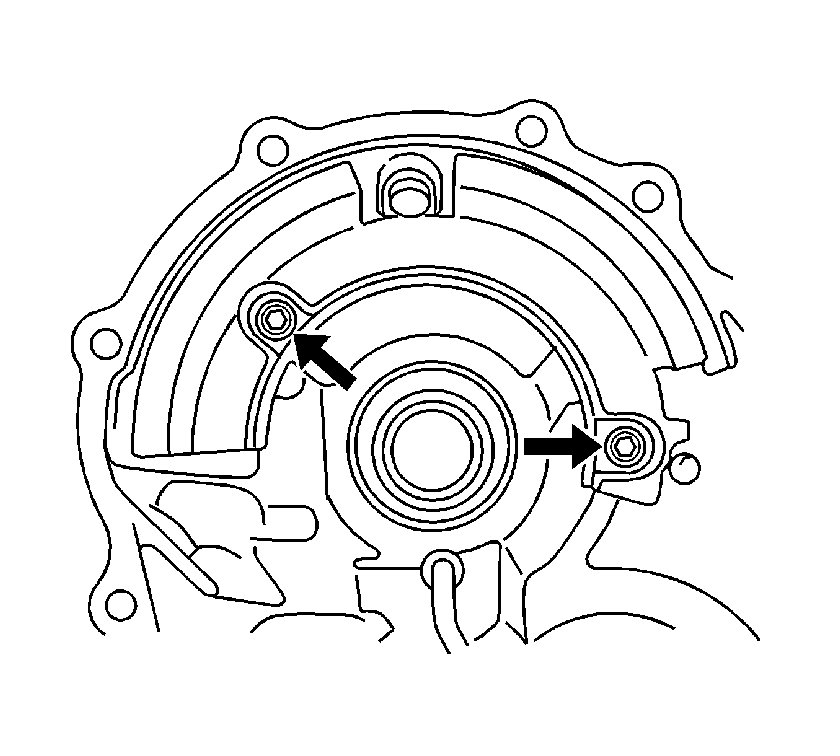
- Remove the 2 park neutral position (PNP) switch retaining bolts, then remove the switch from the transaxle.
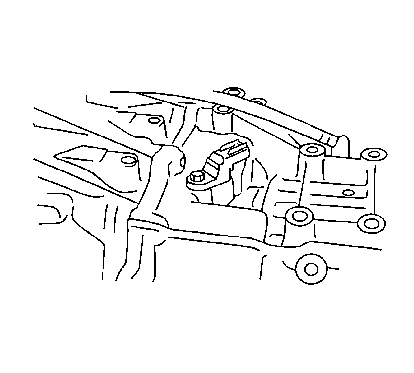
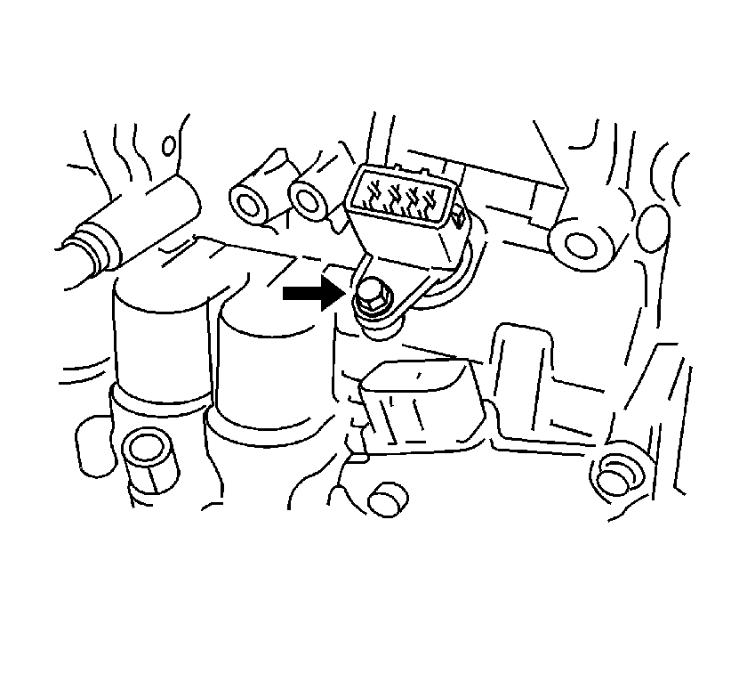
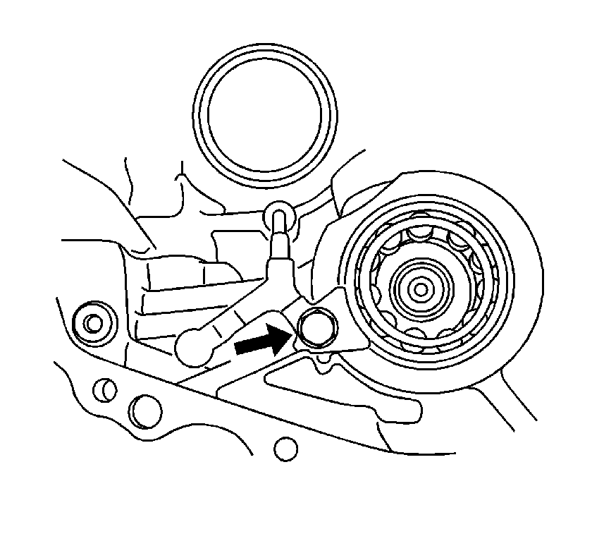
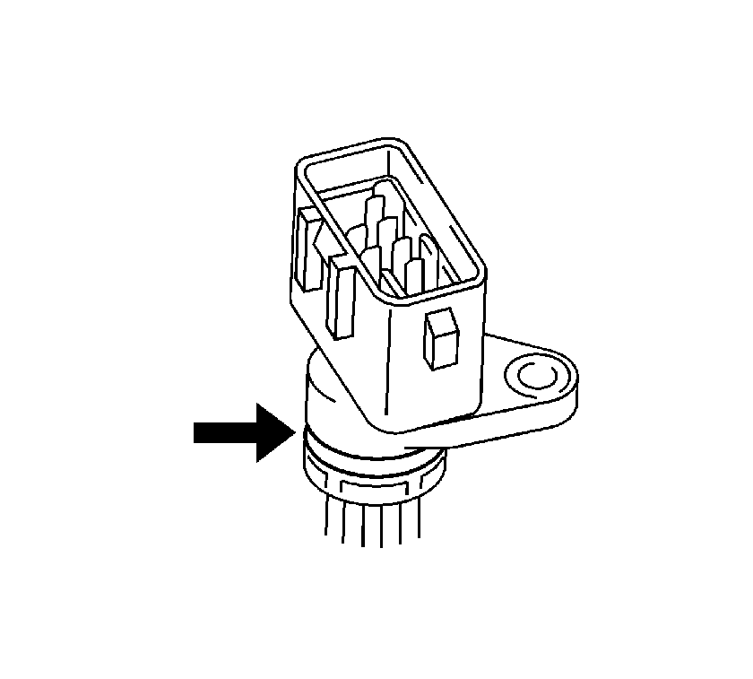
- Remove the bolt and the input shaft turbine sensor from the transaxle case.
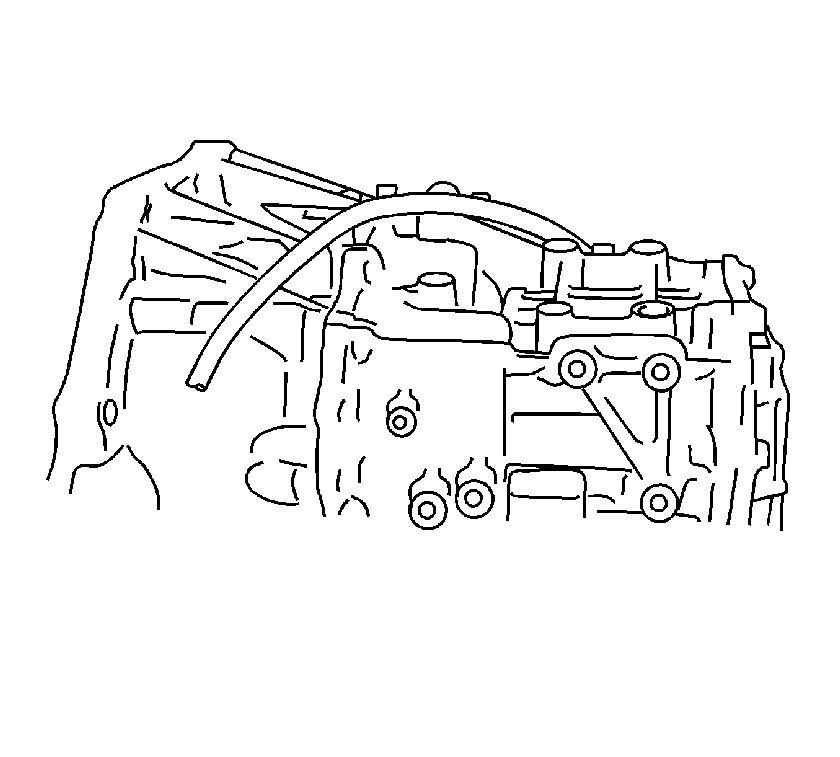
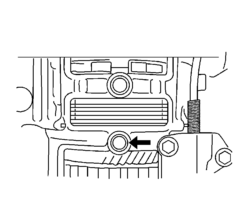
- Remove the breather plug, O-ring and hose from the transaxle case.
- Remove the breather plug.
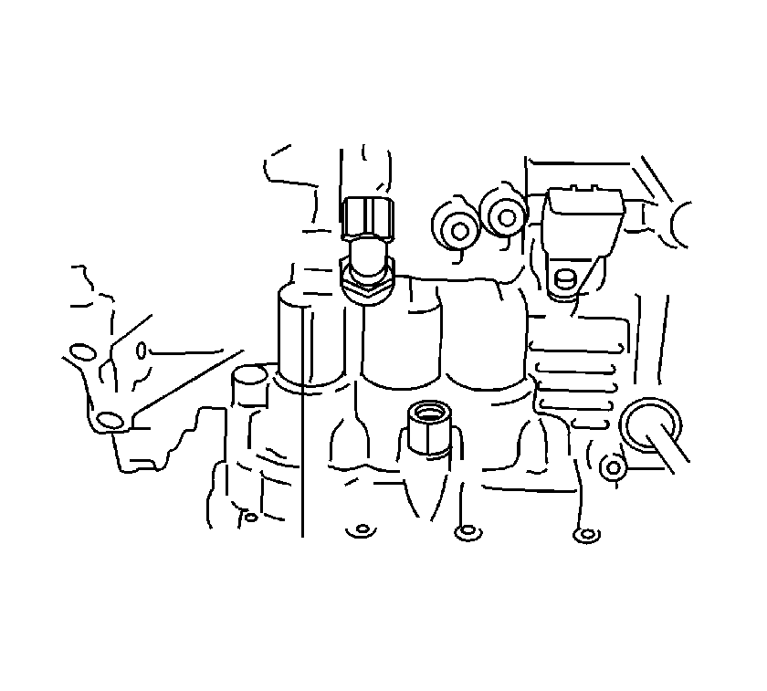
- Remove the outlet oil cooler union from the transaxle.
- Remove the O-rings from the union.
- Remove the inlet oil cooler union from the transaxle.
- Remove the O-rings from the union.
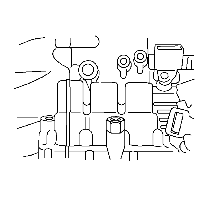
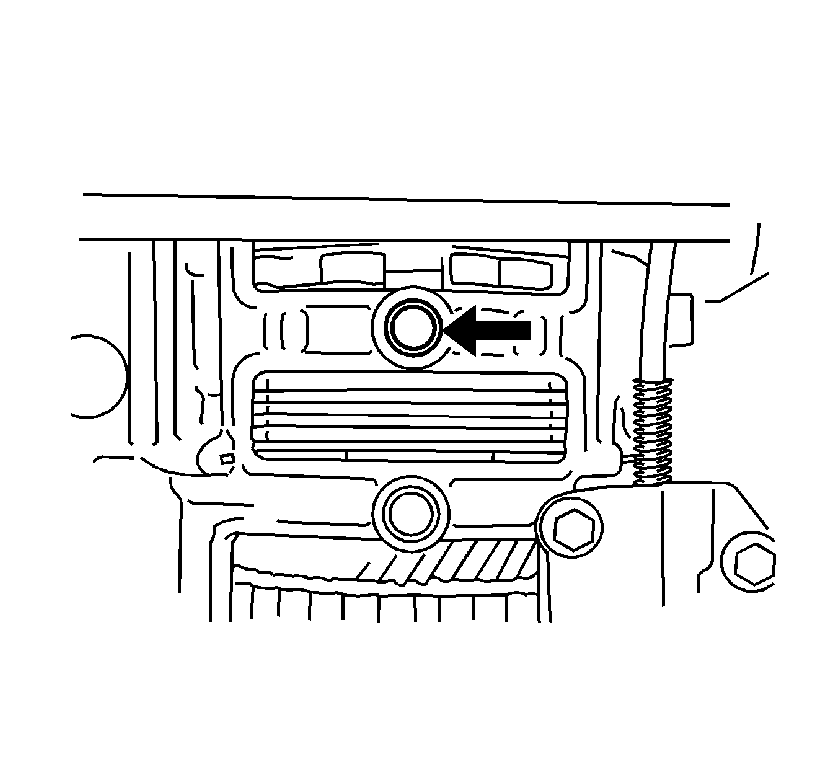
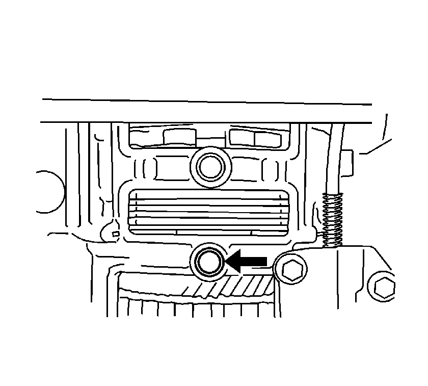
- Remove the 4 transaxle case No.1 plugs from the transaxle housing and transaxle case.
- Remove the transaxle case No.1 plug from the transaxle cases.
- Remove the 5 O-rings from the transaxle case.
- Place the transaxle on 2 blocks of wood.
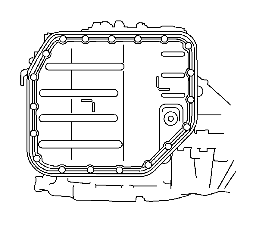
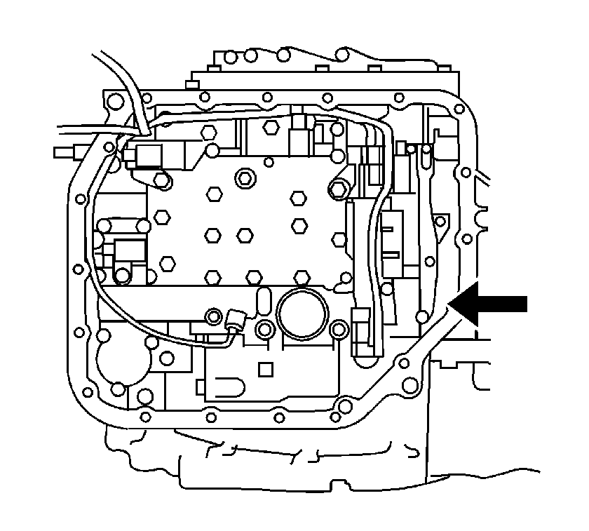
- Remove the oil pan retaining bolts, then the oil pan.
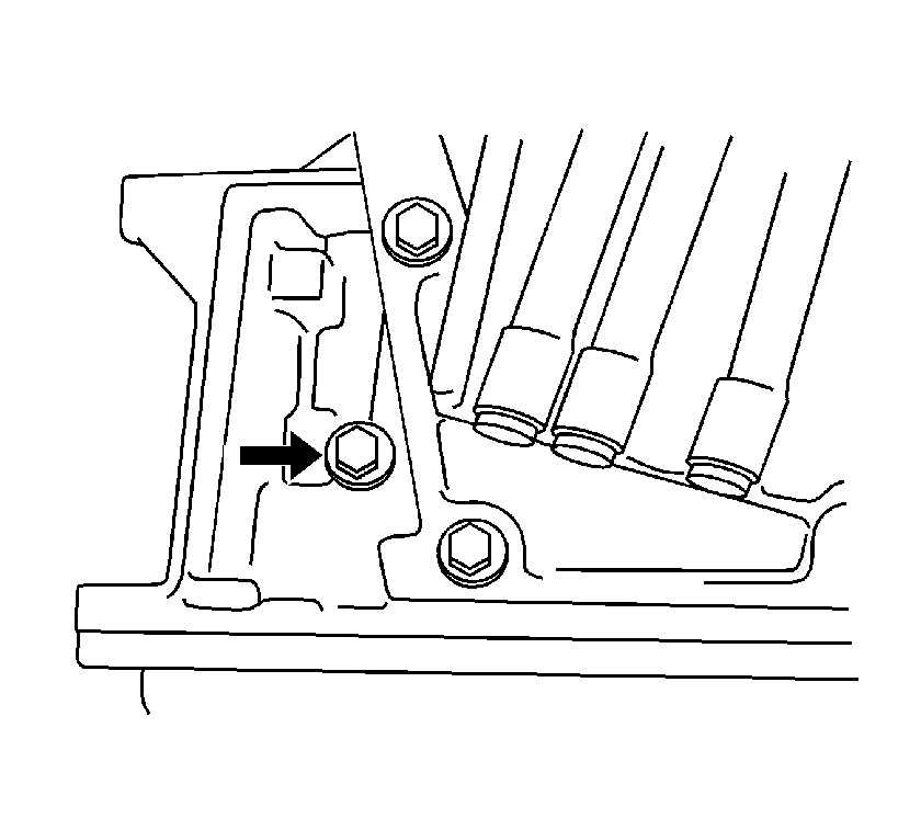
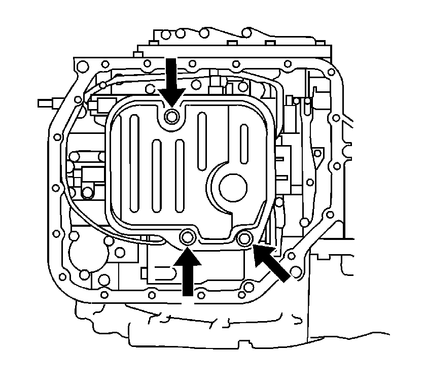
- Remove the 3 oil filter retaining bolts, then the oil filter and gasket.
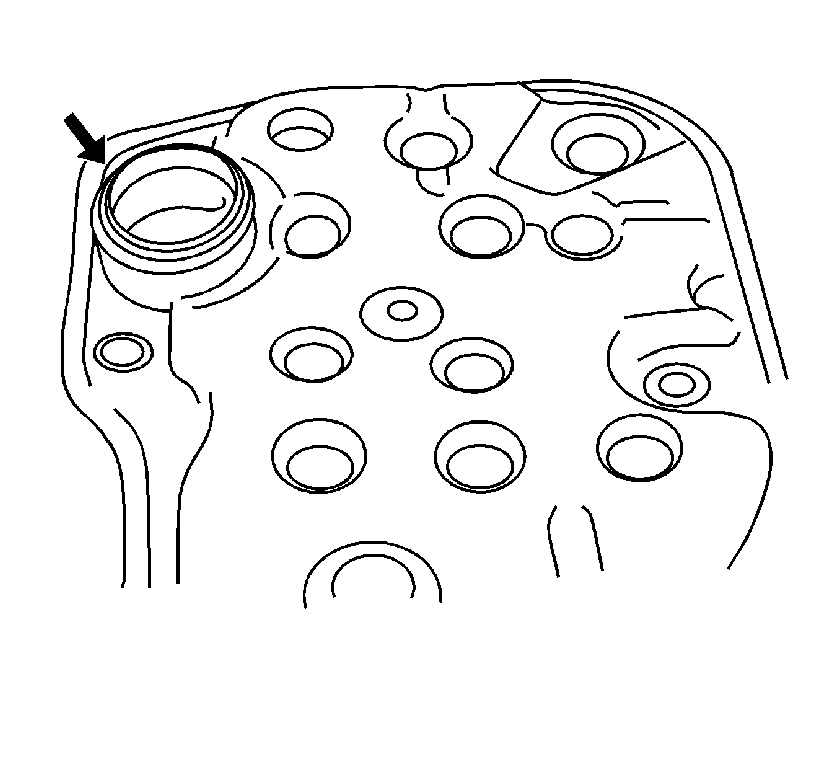
- Remove the O-ring from the oil filter.
- Disconnect the 5 solenoid connectors.
- Remove the bolt, lock plate and automatic transmission fluid (ATF) temperature sensor.
- Remove the 2 bolts, manual detent spring and spring cover.
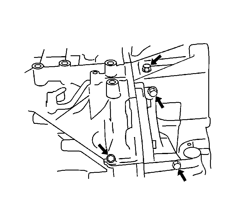
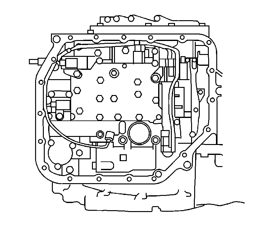
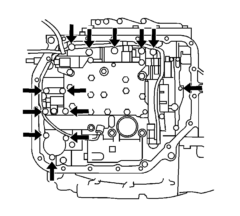
- Remove the 13 valve body retaining bolts.
- Remove the valve body from the transaxle case.
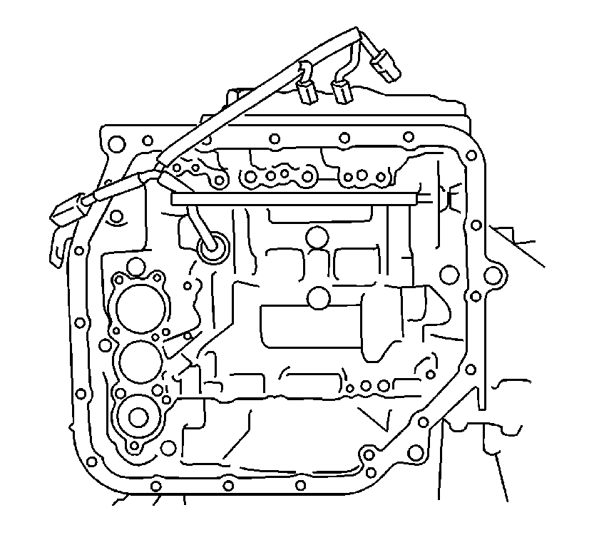
- Remove the transaxle wiring harness retaining bolt.
- Remove the wiring harness from the transaxle case.
- Remove the O-ring from the harness connector.
- Remove the transaxle case 2nd brake gasket.
- Remove the transaxle case gasket.
- Remove the brake drum gasket.
- Remove the check ball body and spring from the transaxle case.
- Cover the B-2 accumulator piston with a shop towel.
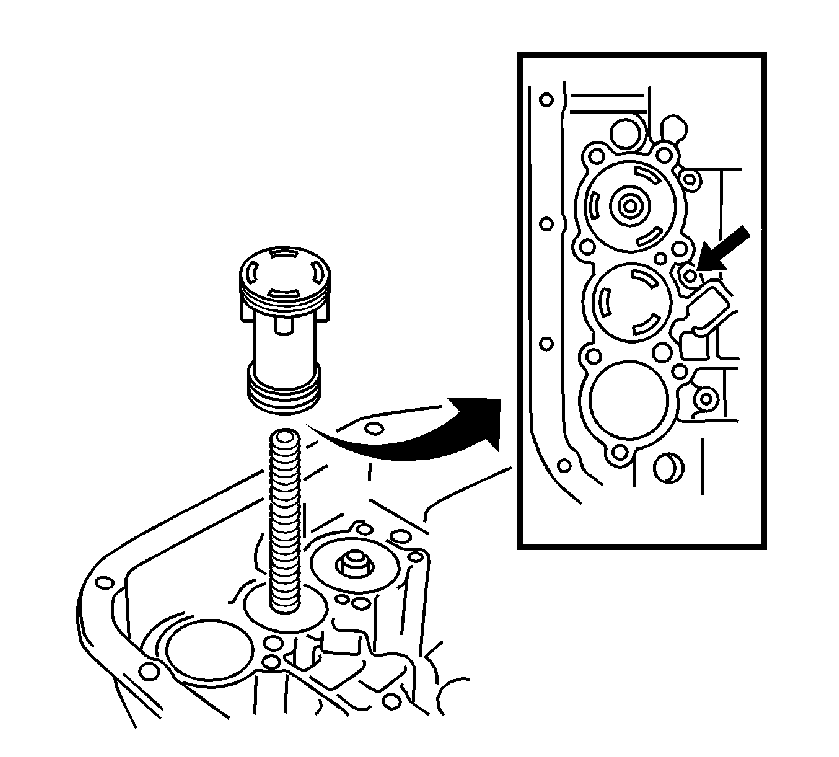
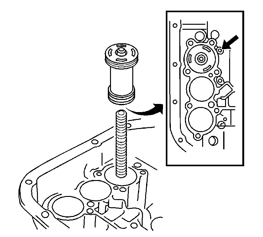
- Using compressed air at low pressure 392 kPa (57 psi) push out the C-3 accumulator piston from the transaxle case.
- Remove the accumulator spring from the transaxle case.
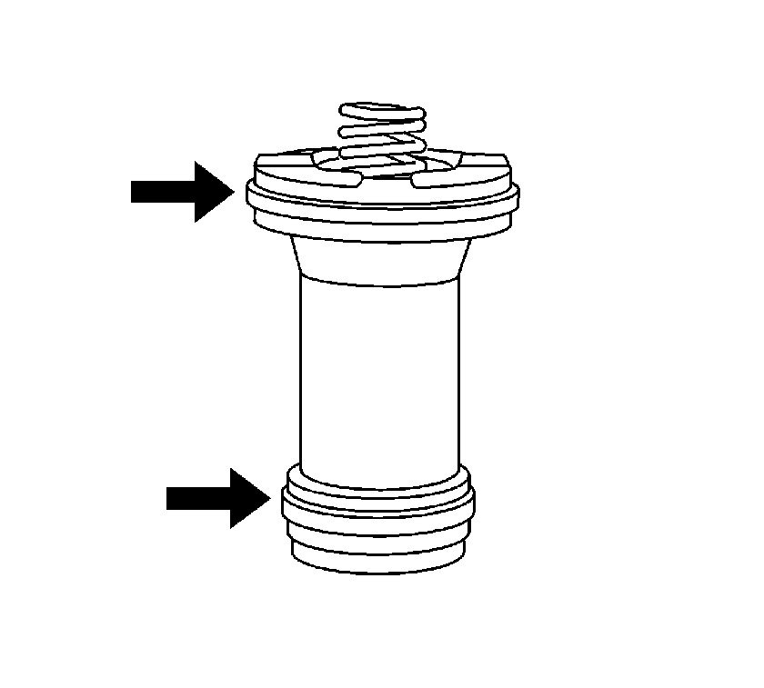
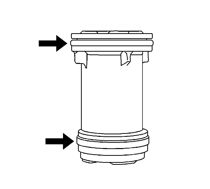
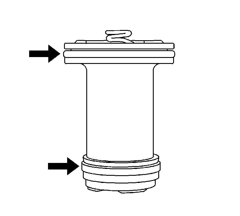
- Remove the 2 O-rings from the accumulator piston.
- Cover the C-3 accumulator piston with a shop towel.
- Using compressed air at low pressure 392 kPa (57 psi) push out the C-3 accumulator piston from the transaxle case.
- Remove the accumulator spring from the transaxle case.
- Remove the 2 O-rings from the accumulator piston.
- Cover the C-2 accumulator piston with a shop towel.
- Using compressed air at low pressure 392 kPa (57 psi) push out the C-2 accumulator piston from the transaxle case.
- Remove the accumulator spring from the transaxle case.
- Remove the 2 O-rings from the accumulator piston.
- Remove the 14 bolts.
- Tap around the transaxle housing with a soft faced hammer to remove the transaxle housing from the transaxle case.
- Remove the 2 bolts and transaxle housing oil separator from the transaxle housing.
- Remove the retaining bolt.
- Remove the bearing lock plate from the transaxle case.
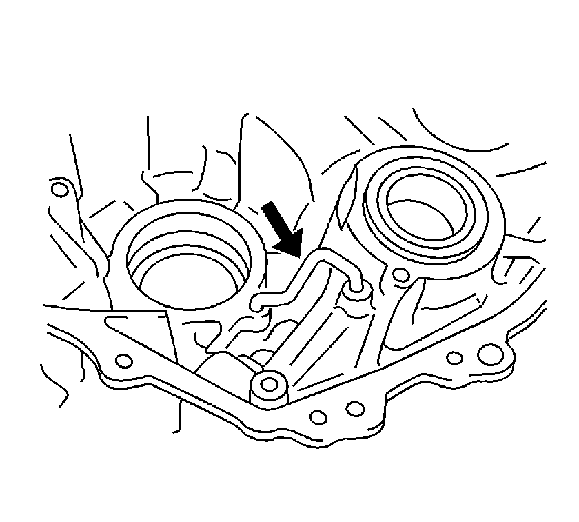
- Remove the bolt and differential gear lube apply tube from the transaxle housing.
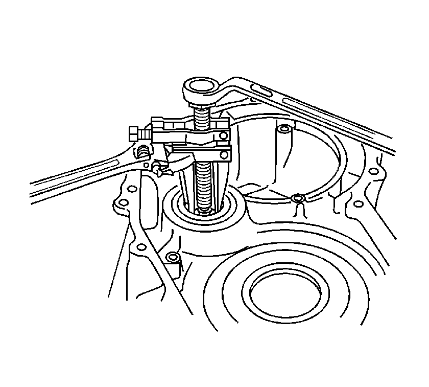
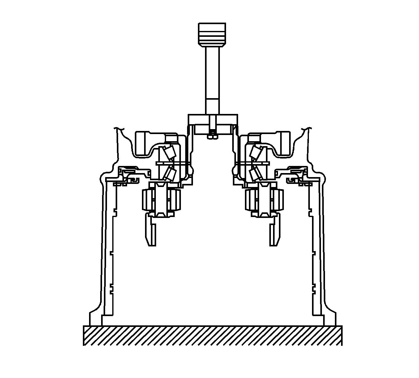
- Using a bearing puller, remove the front drive pinion roller bearing from the transaxle housing.
- Using a dial indicator, measure the end play of the input shaft.
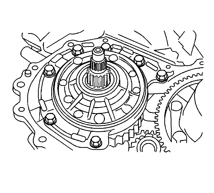
- Remove the 7 oil pump assembly retaining bolts.
- Remove the oil pump assembly from the transaxle case.
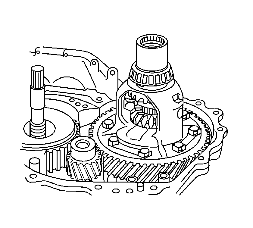
- Remove the differential gear assembly from the transaxle case.
- Using a screwdriver, remove the 2 O/D brake gaskets from the transaxle case.
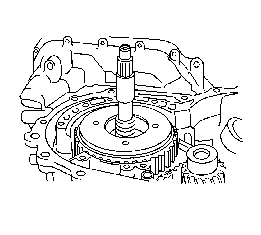
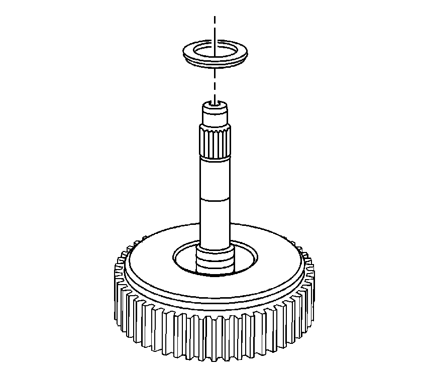
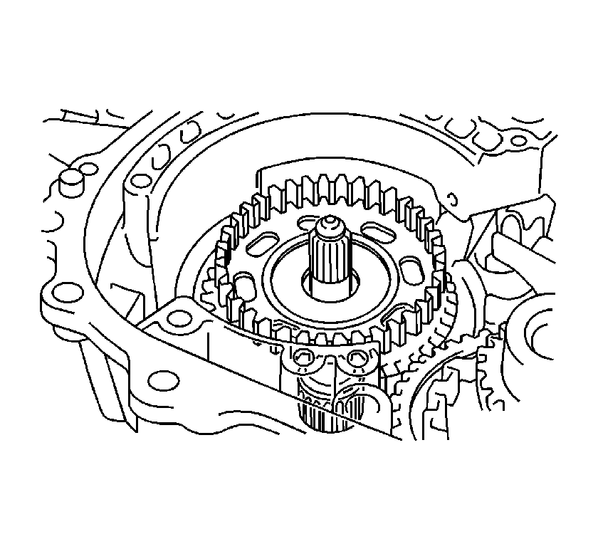
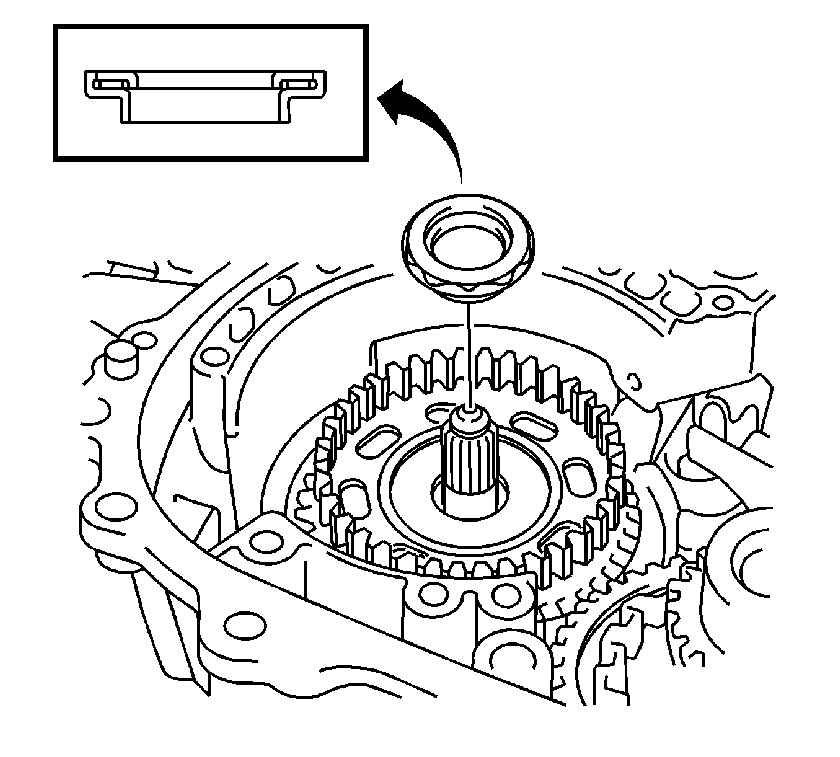
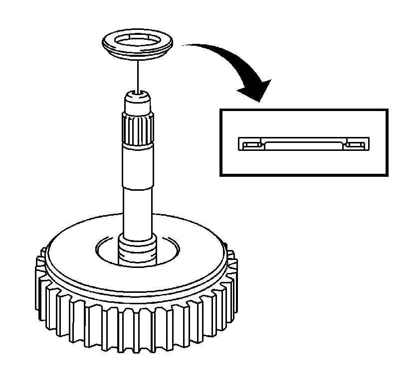
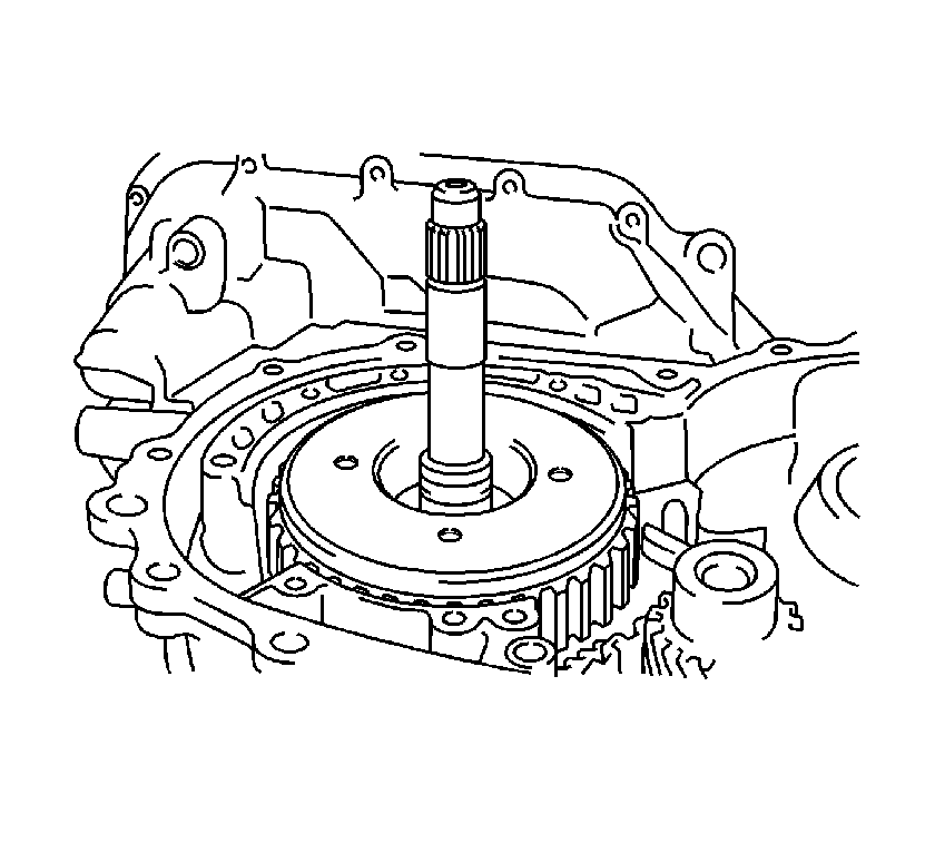
- Remove the input shaft assembly from the transaxle.
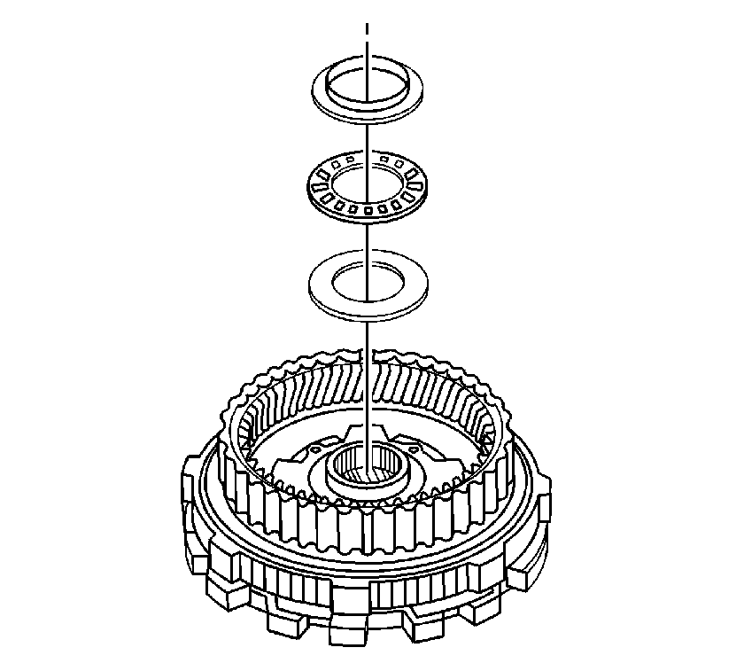
- Remove the stator shaft thrust roller bearing from the input shaft assembly.
- Remove the forward clutch hub thrust roller bearing from the forward clutch hub.
- Remove the forward clutch hub sub-assembly from the transaxle case.
- Remove the 11 transaxle rear cover retaining bolts.
- Tap on the circumference of the transaxle cover with a soft faced hammer to remove the transaxle rear cover from the transaxle case.
- Remove the 4 transaxle case gaskets.
- Using a magnet, remove the rear clutch drum thrust roller bearing.
- Remove the intermediate shaft assembly from the transaxle case.
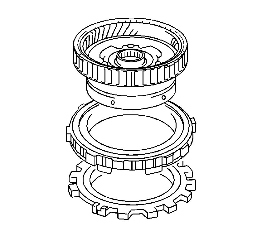
- Remove the 2nd coast and overdrive brake flange, two 2nd coast and overdrive brake discs and two 2nd coast and overdrive brake flanges from the transaxle.
- Check the 2nd coast and overdrive brake discs, plates and flanges. If the sliding surfaces of the discs, plates and flanges are worn or discolored, replace all the discs, plates and flanges.
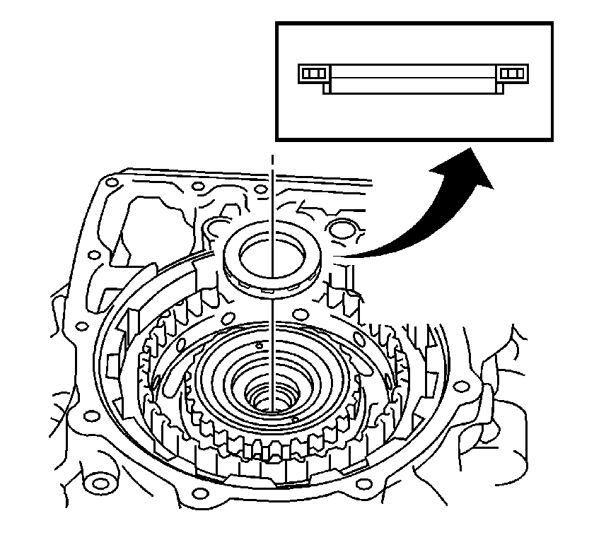
- Using a magnet, remove the C-2 hub thrust bearing race, thrust roller bearing race from the direct clutch hub.
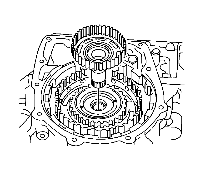
- Remove the direct clutch hub from the transaxle case.
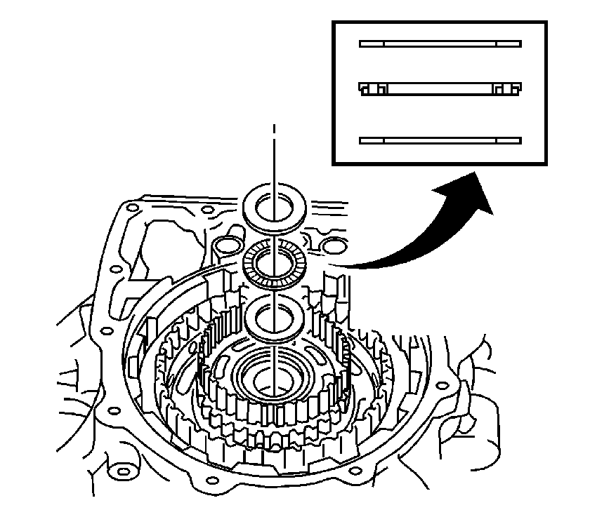
- Using a magnet, remove the rear planetary sun gear No.2 thrust bearing from the rear planetary sun gear assembly.
- Remove the rear planetary sun gear assembly from the transaxle case.
- Remove the rear planetary sun gear thrust roller bearing and thrust washer No. 1 from the rear planetary sun gear.
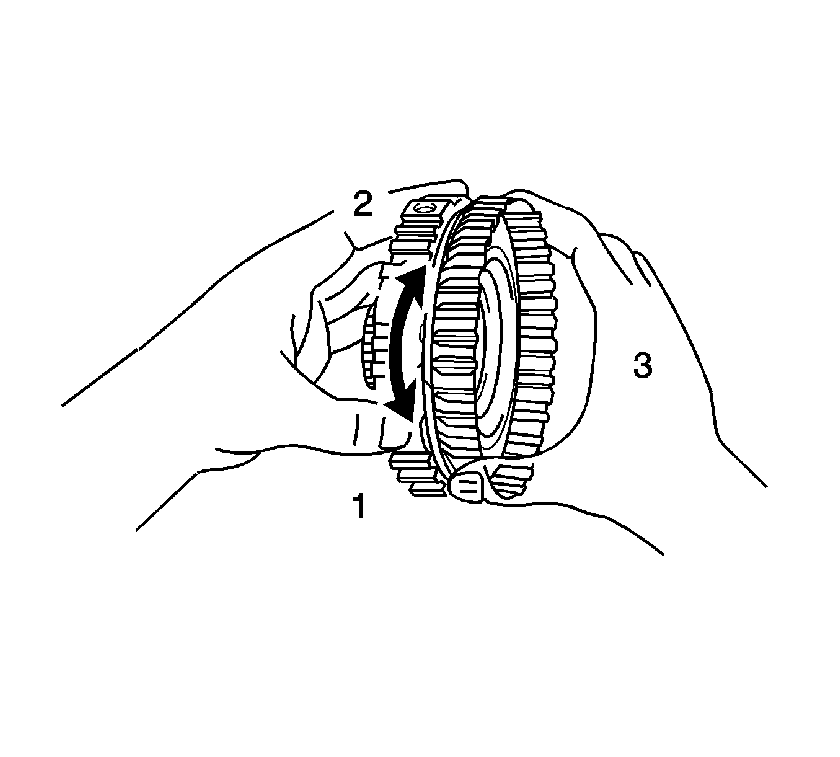
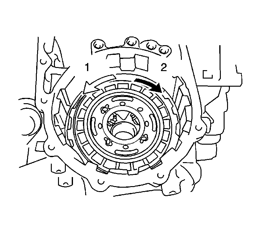
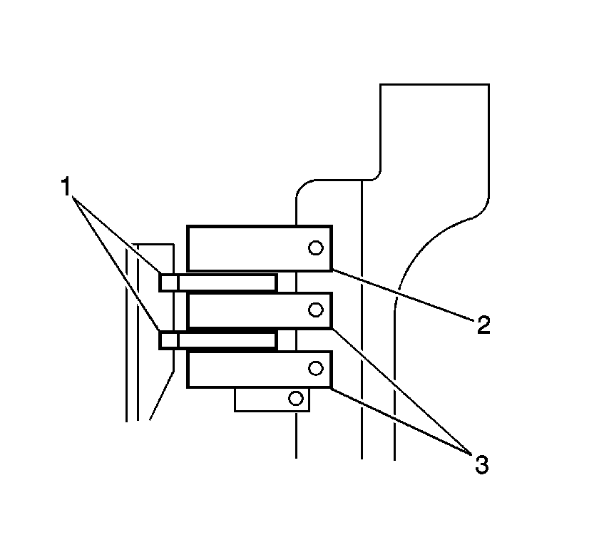
- Hold the rear planetary sun gear (1) and turn the 1 way clutch. The 1 way clutch should turn freely clockwise (2) and should lock if turned counterclockwise (3).
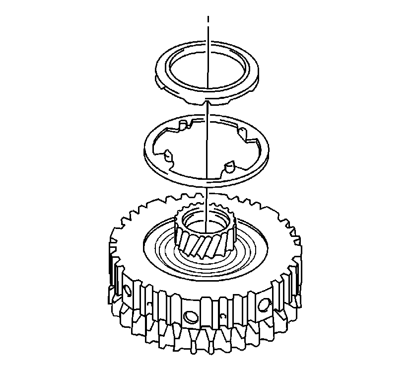
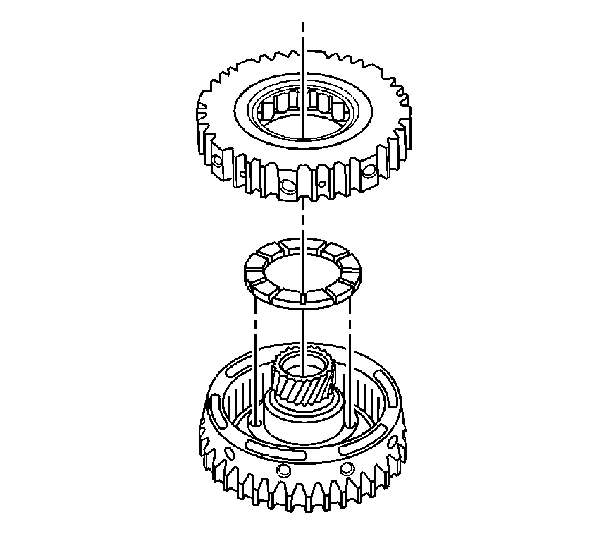
- Remove the 1 way clutch assembly and planetary carrier thrust washer No. 2 from the rear planetary sun gear.
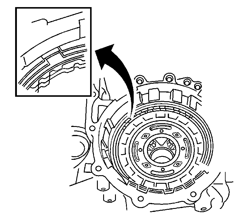
- Using a screwdriver, remove the 2nd coast and overdrive brake flange snap ring from the transaxle case.
- Using a screwdriver, remove the 2nd brake disc snap ring.
- Remove the flange, 3 discs and 3 plates from the transaxle case.
- Check the 2nd brake discs, plates and flanges. If the sliding surfaces of the discs, plates and flanges are worn or discolored, replace all the discs, plates and flanges.
- Remove the 2nd brake piston sleeve from the transaxle case.
- Install the 1 way clutch and thrust washer on the rear planetary sun gear.
- Hold the rear planetary sun gear and turn the 1 way clutch. The 1 way clutch should turn freely counterclockwise (1) and should lock counterclockwise (2).
- Using a screwdriver, remove the rear planetary gear assembly snap ring.
- Remove the rear planetary gear assembly from the transaxle case.
- Remove the rear planetary gear rear thrust roller bearing and 2 bearing races from the rear planetary gear assembly.
- Separate the 2nd brake cylinder, 1 way clutch and the planetary gear.
- Remove the retainer from the 1 way clutch No.2.
- Remove the front planetary sun gear and thrust roller bearing from the transaxle case.
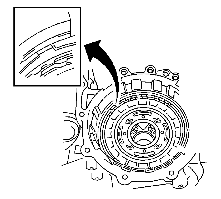
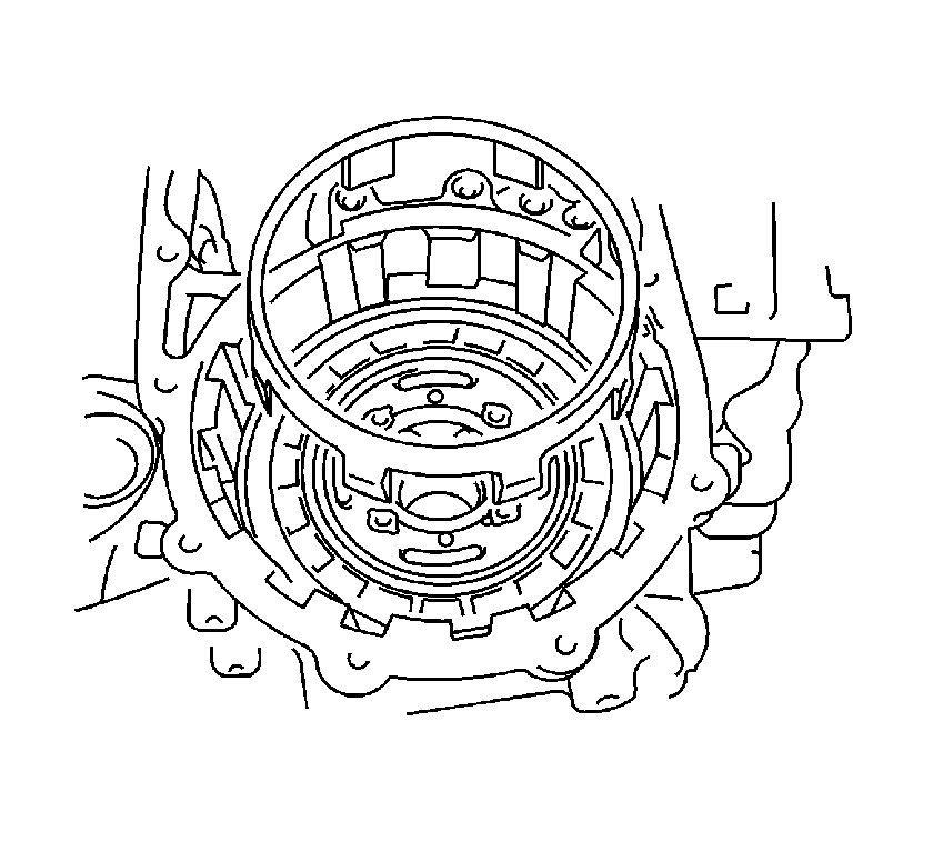
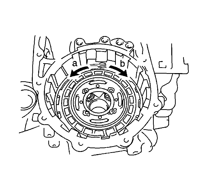
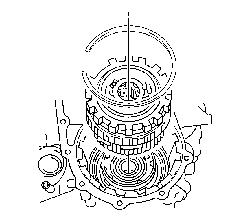
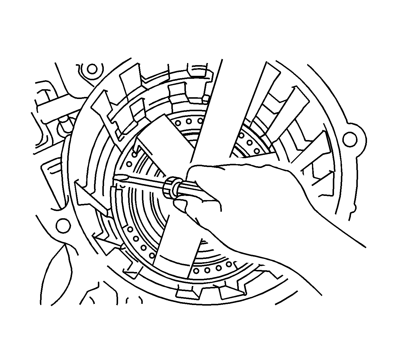
- Using a screwdriver, remove the 1st and reverse brake disc snap ring.
- Check the 1st and reverse brake discs, plates and flange. If the sliding surfaces of the discs, plates and flanges are worn or discolored, replace all the discs, plates and flange.
- Using a press and a screwdriver, remove 1st and reverse return spring sub-assembly snap ring.
- Remove the 1st and reverse brake return spring sub-assembly from the transaxle case.
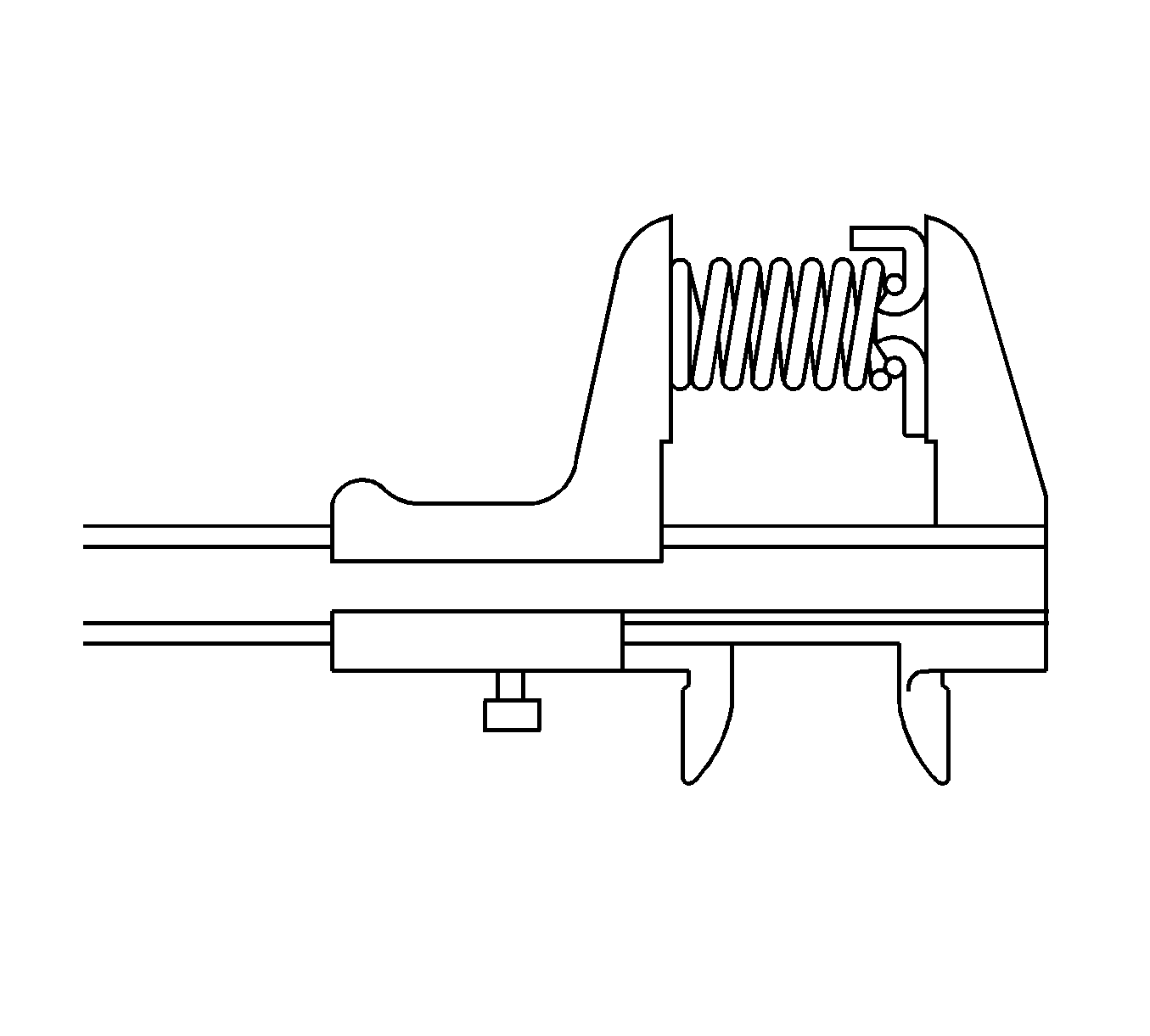
- Using vernier calipers, or an equivalent, measure the free length of the spring together with the spring seat. The free length should be 13.96 mm (0.5496 in). If the length is not as specified, replace the spring.
- Using compressed air at low pressure 392 kPa (57 psi) push out the 1st and reverse brake piston No.2 from the transaxle case.
- Remove the 2 O-rings from the 1st and reverse brake piston No.2.
- Engage the counter driven gear with the parking lock pawl.
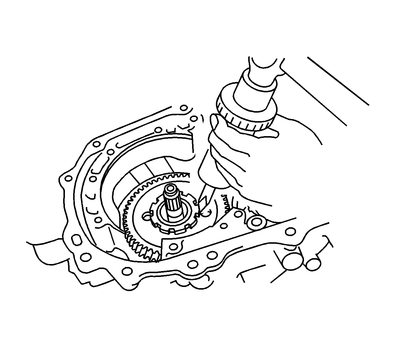
- Using a punch and hammer, unstake the counter drive gear lock washer.
- Remove the counter drive gear nut and lock washer.
- Using a press, remove the planetary gear assembly.
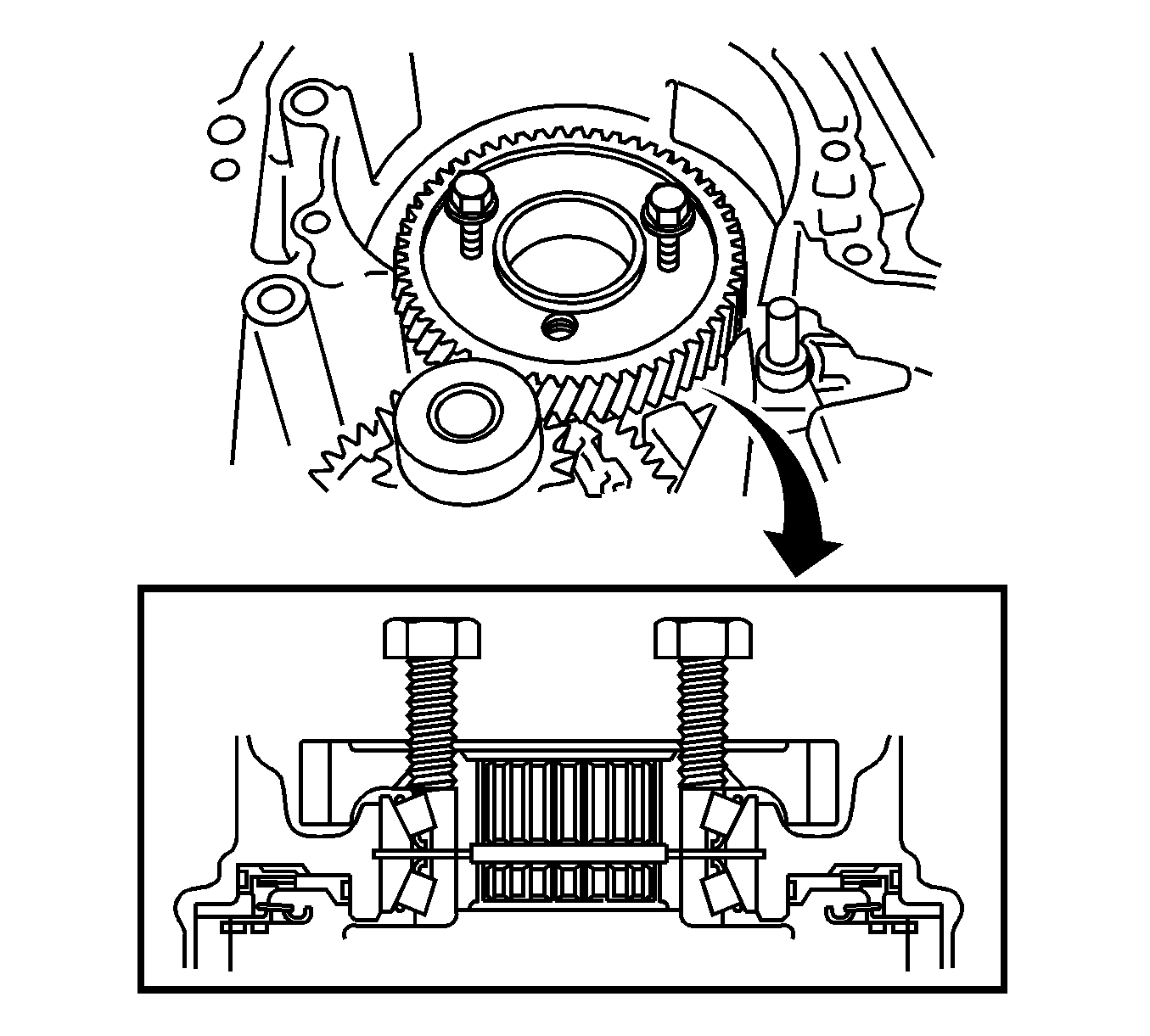
- Install 2 M6 bolts 40-80 mm in length with a 1.0 mm thread pitch into the counter drive gear.
- Tighten the bolts to remove the counter drive gear and front planetary sun gear.
- Remove the 2 radial ball bearings from the counter drive gear and front planetary sun gear.
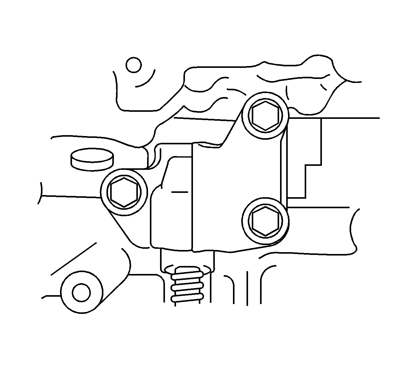
- Remove the 3 parking lock pawl bracket retaining bolts.
- Remove the bracket and cam guide sleeve.
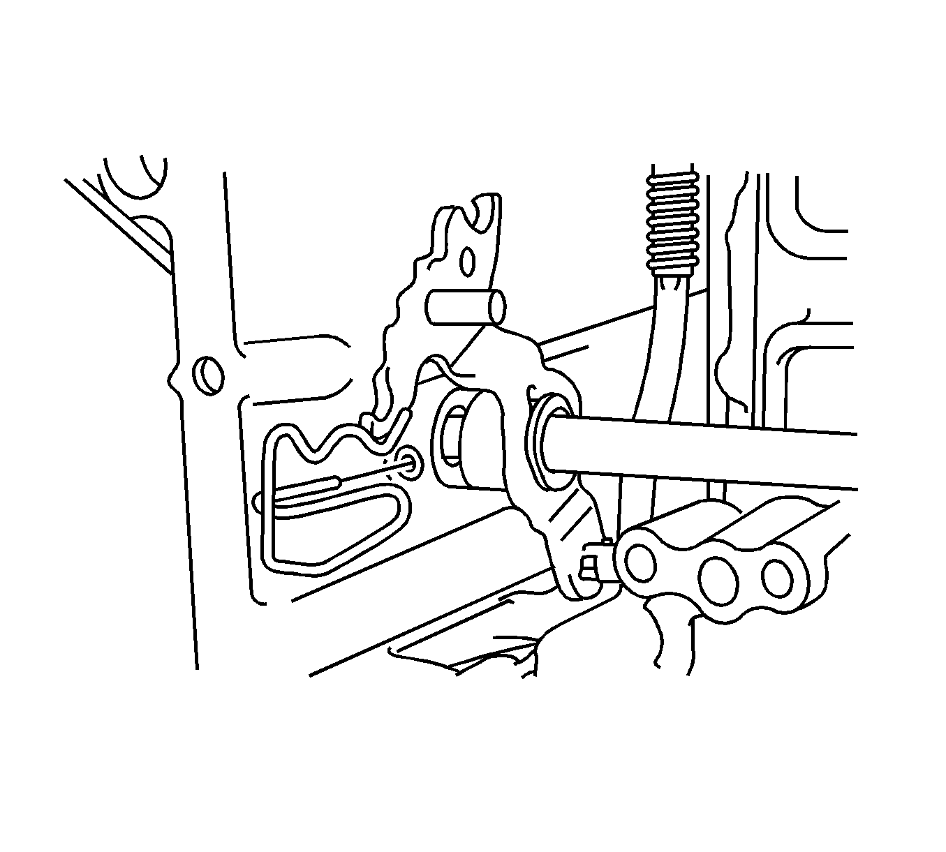
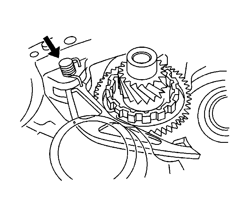
- Remove the manual valve lever shaft retainer spring.
- Using a screwdriver, unstake and remove the spacer.
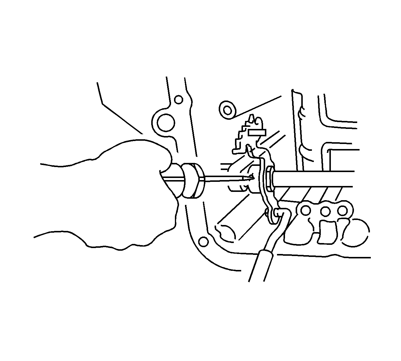
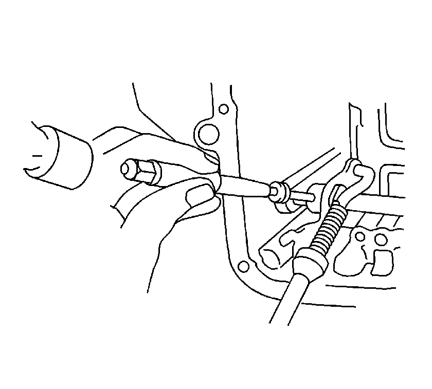
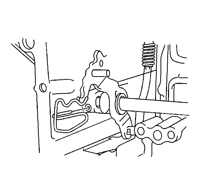
- Using a pin punch and hammer, drive out the retaining pin.
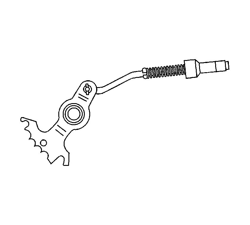
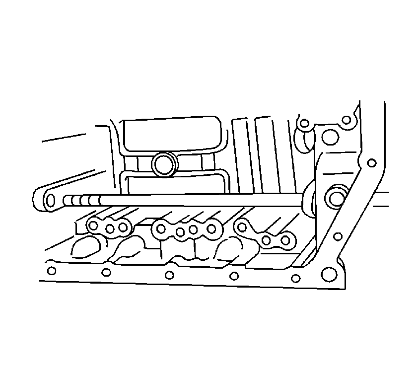
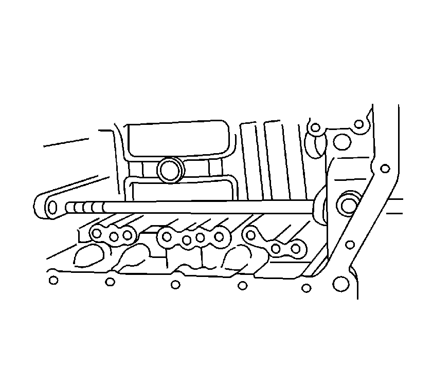
- Remove the manual valve lever shaft and manual valve lever sub-assembly.
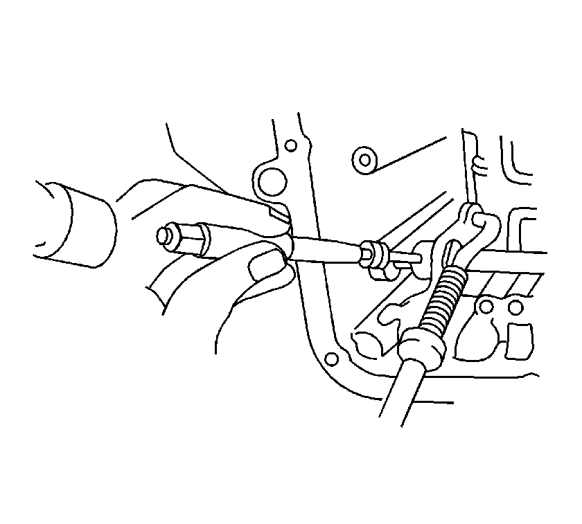
- Remove the parking lock rod sub-assembly from the manual valve lever.
- Remove the manual valve lever shaft from the transaxle case.
- Using a screwdriver, remove the parking lock pawl shaft.
- Remove the parking lock pawl torsion spring and parking lock pawl.
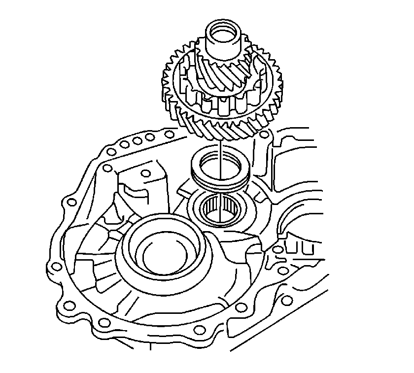
- Remove the counter driven gear, front drive pinion and thrust roller bearing from the transaxle case.
- Using a brass bar and hammer, remove the differential drive pinion plug.
- Using a press, remove the counter driven gear from the differential drive pinion.
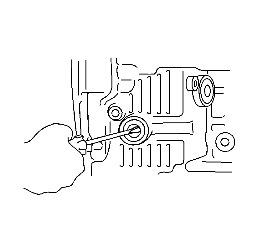
- Using a screwdriver, remove the manual valve lever shaft oil seal.
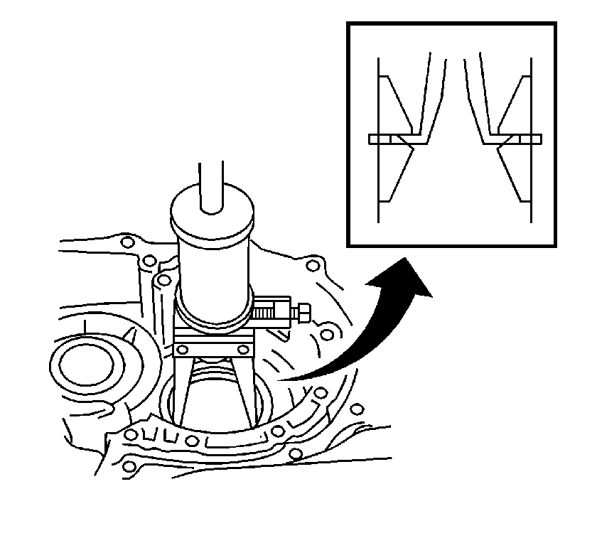
- Using a bearing puller and slide hammer, remove the 2 right side counter drive gear bearing inner races from the transaxle case.
- Using a bearing puller and slide hammer, remove the left side counter drive gear bearing outer race from the transaxle case.
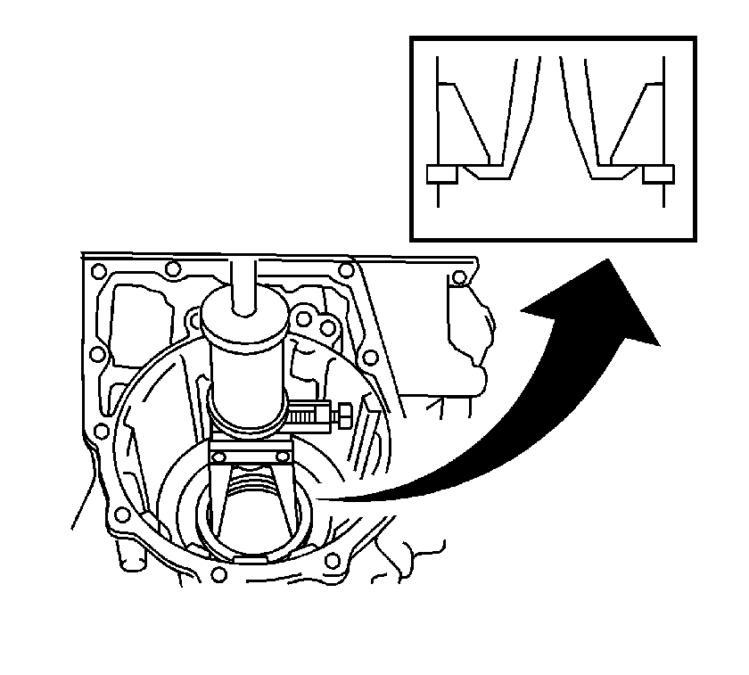
- Using a bearing puller and slide hammer, remove the counter drive gear bearing rear outer race from the transaxle case.
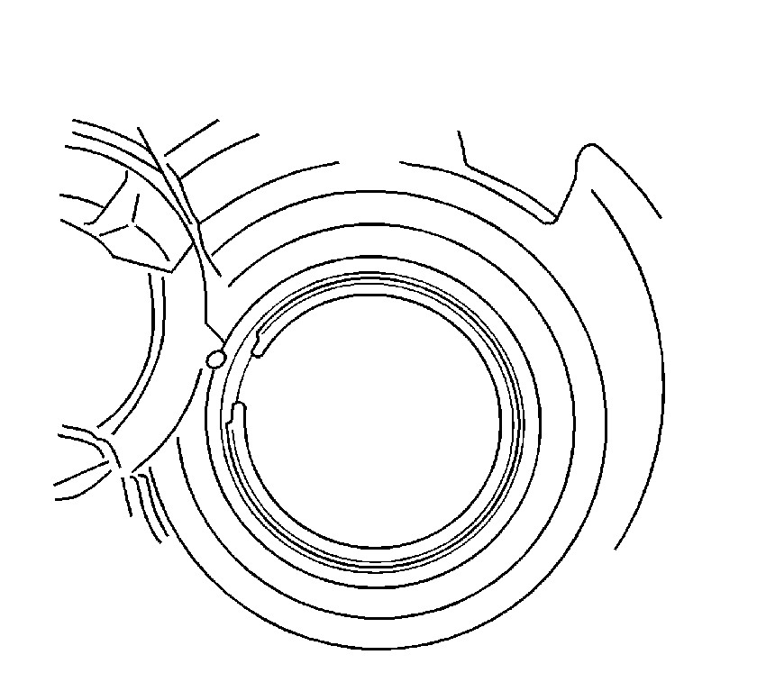
- Using a screwdriver, remove the counter drive gear hole snap ring from the transaxle case.
- Remove the remaining oil seals from the transaxle case.
- Using a seal driver and hammer, install a new transaxle case oil seal. Oil seal installation depth is 3.5-4.5 mm (0.086-0.126 in).
- Using a seal driver and hammer, install a new front transaxle case oil seal. Oil seal installation depth is 2.2-3.2 mm (0.138-0.178 in).
- Using a bearing driver and hammer, install the front drive pinion rear tapered roller bearing into the transaxle case.
- Using a screwdriver, install the counter drive gear hole snap ring in the transaxle case.
- Using a bearing driver and hammer, install the counter drive gear left side bearing outer race in the transaxle case.
- Using a bearing driver and hammer, install the right counter drive gear bearing outer race in the transaxle case.
- Using a seal driver and hammer, install a new manual valve lever shaft oil seal flush with the transaxle case.
- Using a press, install the counter driven gear on the differential drive pinion.
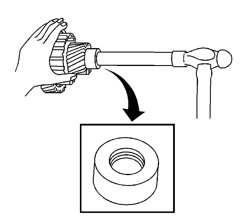
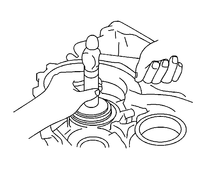
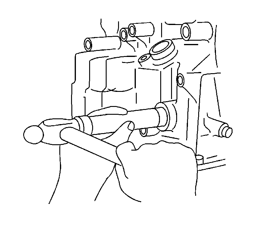
- Using a socket and soft faced hammer, install a new differential drive pinion plug in the differential drive pinion.
- Install the counter drive gear and drive pinion thrust bearing in the transaxle case.
- Apply T-IV automatic transmission fluid to the parking lock pawl shaft.
- Install the parking lock pawl, torsion spring and shaft in the transaxle case.
- Install the manual valve lever shaft in the transaxle case.
- Install the parking lock rod sub-assembly to the manual valve lever.
- Apply T-IV automatic transmission fluid to the manual valve lever sub-assembly shaft.
- Install the manual valve lever and a new manual valve lever spacer on the manual valve lever shaft.
- Using a pin punch and hammer, install the pin.
- Turn the spacer and manual valve lever shaft to align the small hole to locate the staking position in the spacer with the staking position mark on the manual valve lever shaft.
- Using a pin punch, stake the spacer through the small hole.
- Ensure that the spacer does not turn freely.
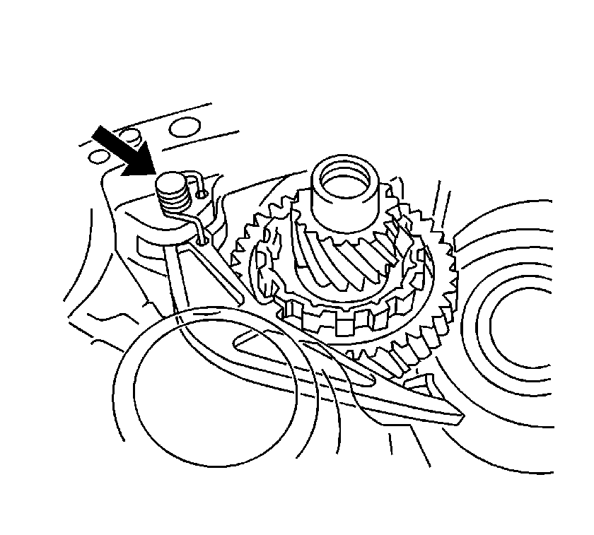
- Install the manual valve lever shaft retaining spring.
- Install the cam guide sleeve, parking lock pawl bracket and the 3 retaining bolts.
- Using a press, install the counter drive gear to the transaxle case.
- Using a press, install the planetary gear assembly to the transaxle case.
- Engage the counter driven gear with the parking lock pawl.
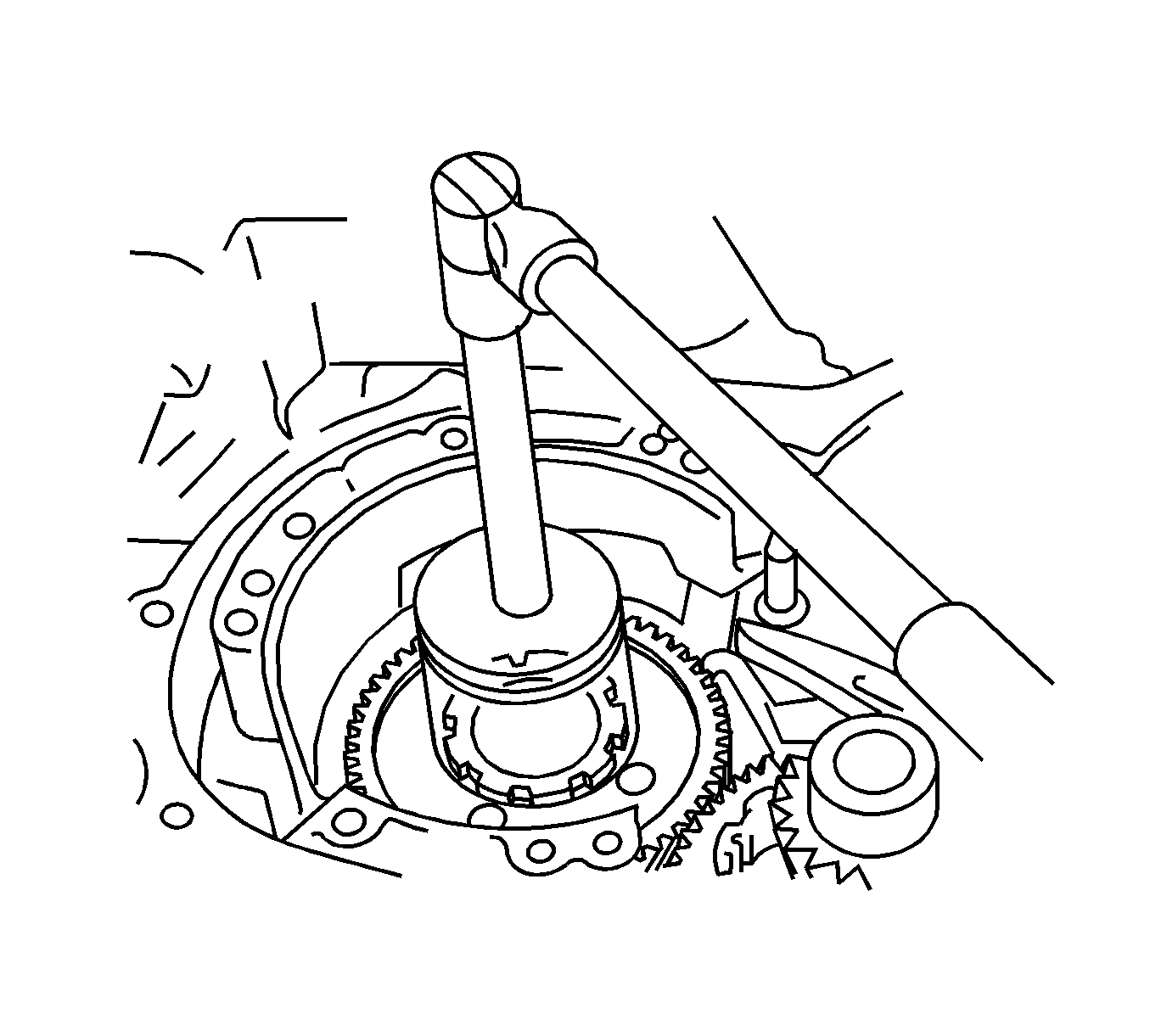
- Install a new lock washer and nut.
- While turning the counter drive gear, measure the rotating torque.
- Using a punch and hammer, stake the lock washer.
- Install 2 new O-rings on the 1st and reverse brake piston No.2.
- Install the 1st and reverse brake piston in the transaxle case.
- Install the 1st and reverse brake return spring sub-assembly into the transaxle.
- Using a press and a screwdriver, install the snap ring.
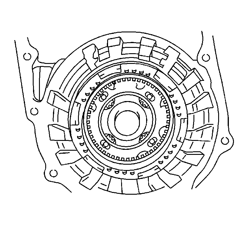
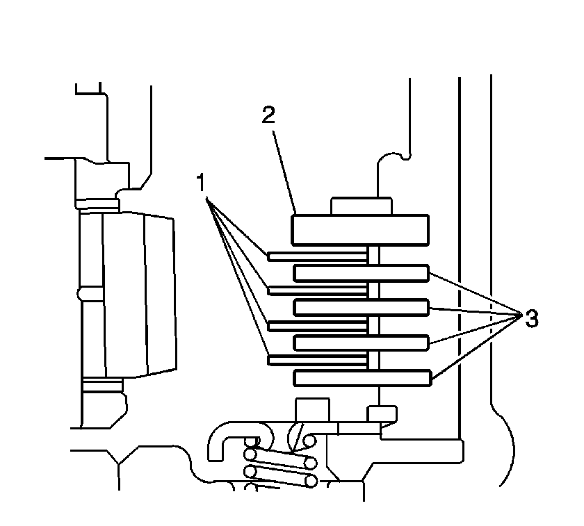
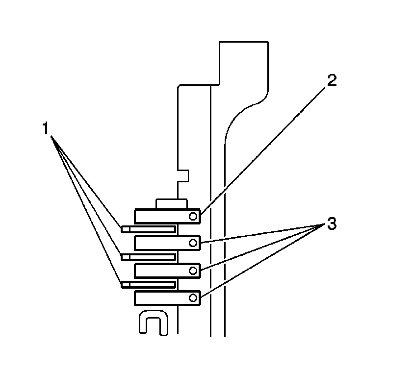
- Install the 4 1st and reverse brake plates (3), 4 brakes discs (1) and the flange (2) in the order shown into the transaxle case.
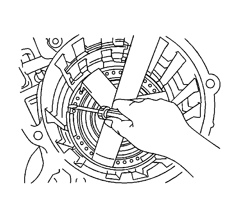
- Using a screwdriver, install the snap ring.
- Using a dial indicator, measure the pack clearance using compressed air.
- Install the front planetary sun gear and roller bearing on the planetary gear assembly.
- Install the outer race retainer to the 1 way clutch No.2.
- Install the 1 way clutch No. 2 and the 2nd brake piston assembly to the rear planetary gear assembly.
- Install the thrust bearing race No.2, planetary gear rear needle roller bearing and the thrust bearing race No.1 to the rear planetary gear assembly.
- Install the rear planetary gear assembly in the transaxle case.
- Using a screwdriver, install the snap ring.
- Check that the rear planetary gear assembly turns freely counterclockwise (1) and locks clockwise (2).
- Install the 2nd brake piston sleeve in the transaxle case.
- Install the 3 2nd brake discs (1), 3 2nd brake plates (3) and the flange (2) in the order shown into the transaxle case.
- Using a screwdriver, install the snap ring into the transaxle case.
- Using a dial indicator, measure the pack clearance of the 2nd brake using compressed air.
- Using a screwdriver, install the 2nd coast and overdrive brake flange hole snap ring into the transaxle case.
- Install the thrust washer No.2 on the rear planetary gear assembly.
- Install the 1 way clutch assembly on the rear planetary sun gear assembly.
- Hold the rear planetary sun gear (3) and turn the 1 way clutch assembly. The 1 way clutch assembly should turn freely clockwise (2) and should lock counterclockwise (1).
- Install the rear planetary sun gear thrust roller bearing and washer to the rear planetary sun gear.
- Install the rear planetary sun gear assembly.
- Install the rear planetary sun gear No.2 thrust bearing to the rear planetary sun gear.
- Install the direct clutch hub.
- Install the thrust bearing race No.3 thrust roller bearing and the hub thrust bearing race to the direct clutch hub.
- Install the 2 discs (1), 2 plates (3) and the flange (2) in the order shown into the transaxle case.
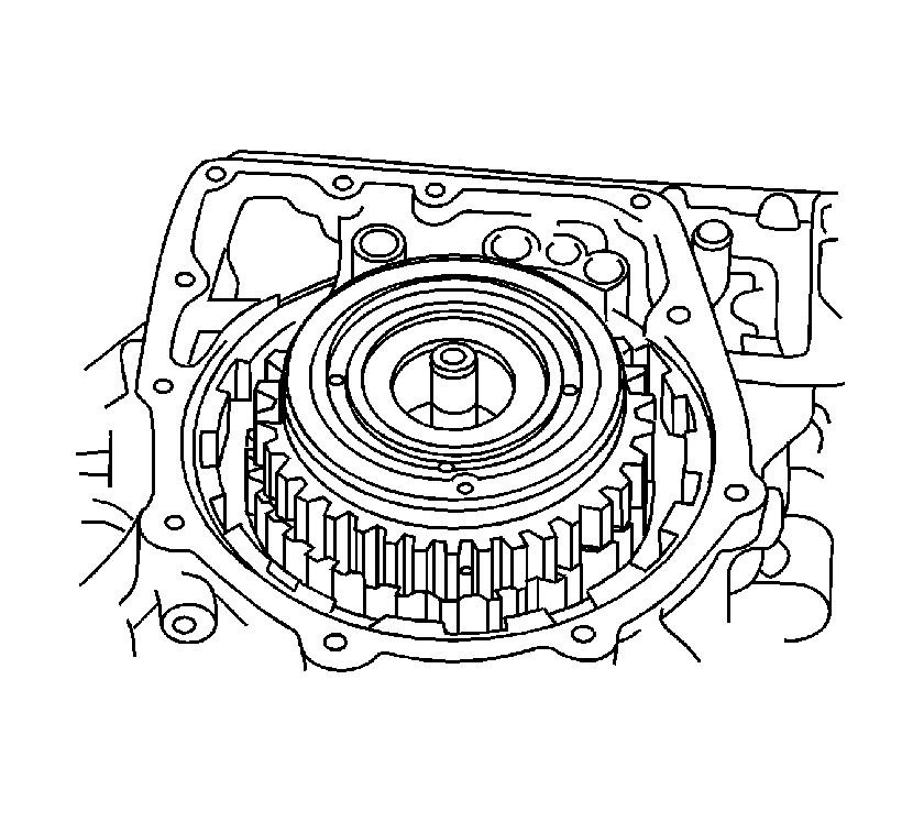
- Install the intermediate shaft assembly in the transaxle case.
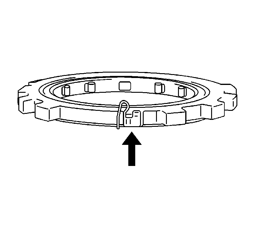
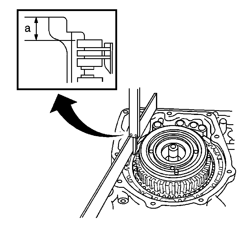
- Place a straight edge on the transaxle case and measure the distance between the 2nd coast and O/D brake flange.
- Using vernier calipers, measure dimension (a).
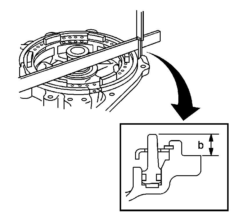
- Place a straight edge on the O/D brake piston, then measure distance (b) between the transaxle rear cove and the straight edge, using vernier calipers.
- Calculate the piston stroke by subtracting distance (b) from distance (a) which will equal one of the following flange thicknesses: 4.0 mm (0.1575 in), 4.2 mm (0.1654 in), 4.4 mm (0.1732 in), 4.6 mm (0.1811 in).
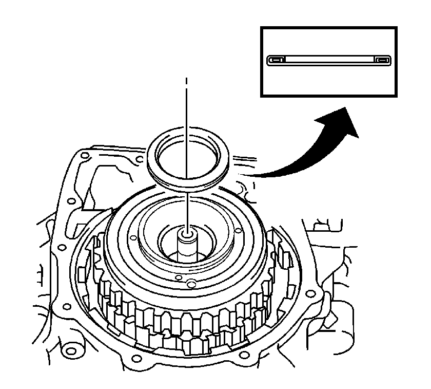
- Using feeler gages, measure the pack clearance. The clearance should be 2.091-2.491 mm (0.0823-0.0981 in). If the clearance is not as specified, install a different thickness flange.
- Install the rear clutch drum thrust roller bearing to the intermediate shaft.
- Install the transaxle rear cover and 11 retaining bolts, to inspect the intermediate shaft assembly.
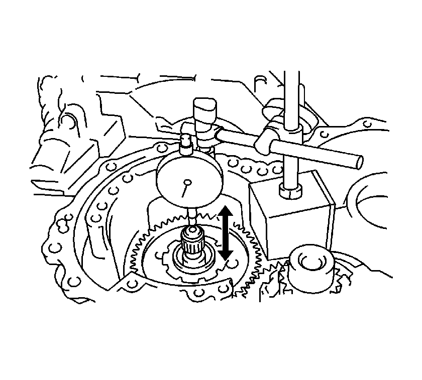
- Using a dial indicator, measure the endplay of the intermediate shaft. The endplay should be between 0.204-0.966 mm (0.008-0.038 in).
- Remove the 11 bolts and transaxle rear cover.
- Install the 4 new gaskets in the transaxle case.
- Apply RTV Silicone Sealant GM P/N 12346240 (Canadian P/N 10953493), or the equivalent, to the transaxle rear cover.
- Install the transaxle rear cover and 11 retaining bolts.
- Install the forward clutch hub sub-assembly into the transaxle case.
- Install the forward clutch hub thrust roller bearing to the forward clutch hub.
- Install the stator shaft thrust roller bearing to the input shaft assembly.
- Install the input shaft assembly in the transaxle case.
- Install 2 new overdrive brake gaskets in the transaxle case.
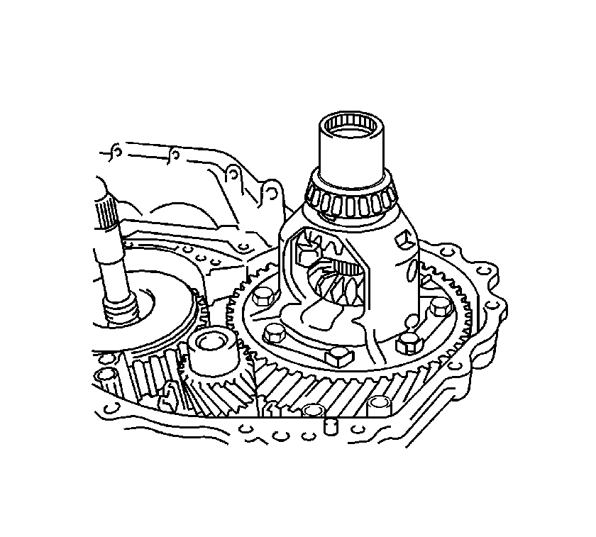
- Install the differential gear assembly in the transaxle case.
- Install the oil pump and the 7 retaining bolts.
- Ensure that the input shaft turns smoothly.
- Using a dial indicator, measure the endplay in the axial direction. Endplay should be 0.37-1.29 mm (0.0146-0.0508 in). If the endplay is not as specified, replace the thrust roller bearing.
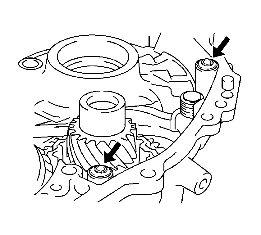
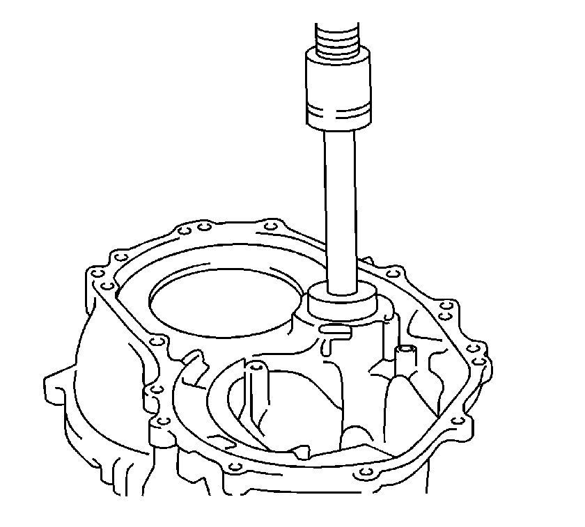
- Install the front drive pinion front tapered roller bearing in the transaxle housing.
- Using a press, install the cylindrical roller bearing into the transaxle case.
- Install the differential gear lube apply tube.
- Install the bearing lock plate and bolt in the transaxle case.
- Install the transaxle housing oil separator and the 2 bolts in the transaxle case.
- Apply RTV Silicone Sealant GM P/N 12346240 (Canadian P/N 10953493), or the equivalent, to the transaxle housing.
- Install the transaxle housing and 14 bolts to the transaxle case.
- Apply T-IV automatic transmission fluid to the 2 new C2 accumulator O-rings, then install the O-rings.
- Install the spring and the C2 accumulator piston into the transaxle case.
- Apply T-IV automatic transmission fluid to the 2 new C3 accumulator O-rings, then install the O-rings.
- Install the spring and the C3 accumulator piston into the transaxle case.
- Apply T-IV automatic transmission fluid to the 2 new B2 accumulator O-rings, then install the O-rings.
- Install the spring and the B2 accumulator piston into the transaxle case.
- Install the spring and check ball body into the transaxle case.
- Install a new brake drum gasket into the transaxle case.
- Install a new transaxle case gasket into the transaxle case.
- Install a new transaxle case 2nd brake gasket into the transaxle case.
- Coat a new transmission wire connector O-ring with T-IV automatic transmission fluid, then install the O-ring.
- Install the transmission wiring harness into the transaxle case.
- Install the wiring harness retaining bolt.
- Install the valve body in the transaxle case.
- Install the valve body bolts.
- Install the detent spring, spring cover.
- Install the detent spring bolts.
- Connect the 5 solenoid connectors.
- Coat the new ATF temperature sensor O-ring with T-IV automatic transmission fluid, then install the O-ring.
- Install the ATF sensor, lock plate and bolt.
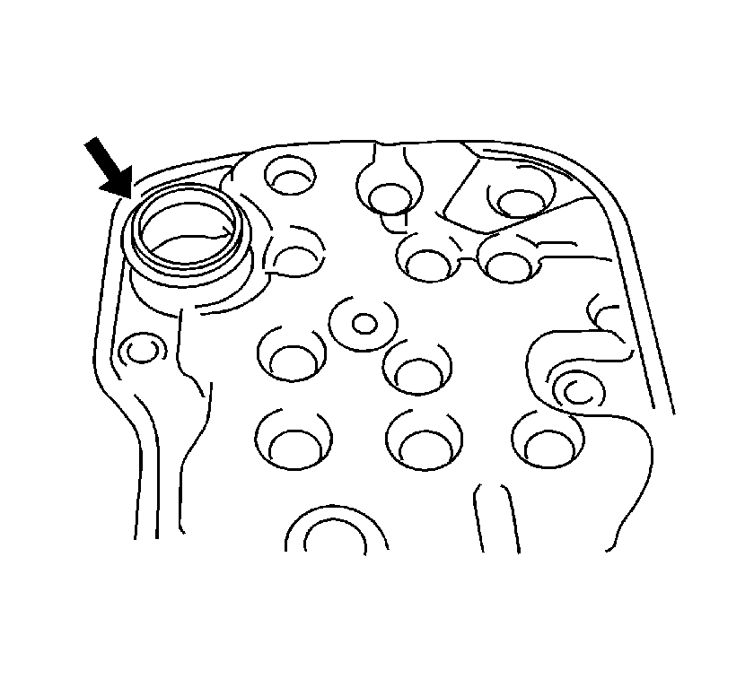
- Coat a new valve body oil filter O-ring with T-IV automatic transmission fluid, then install the O-ring.
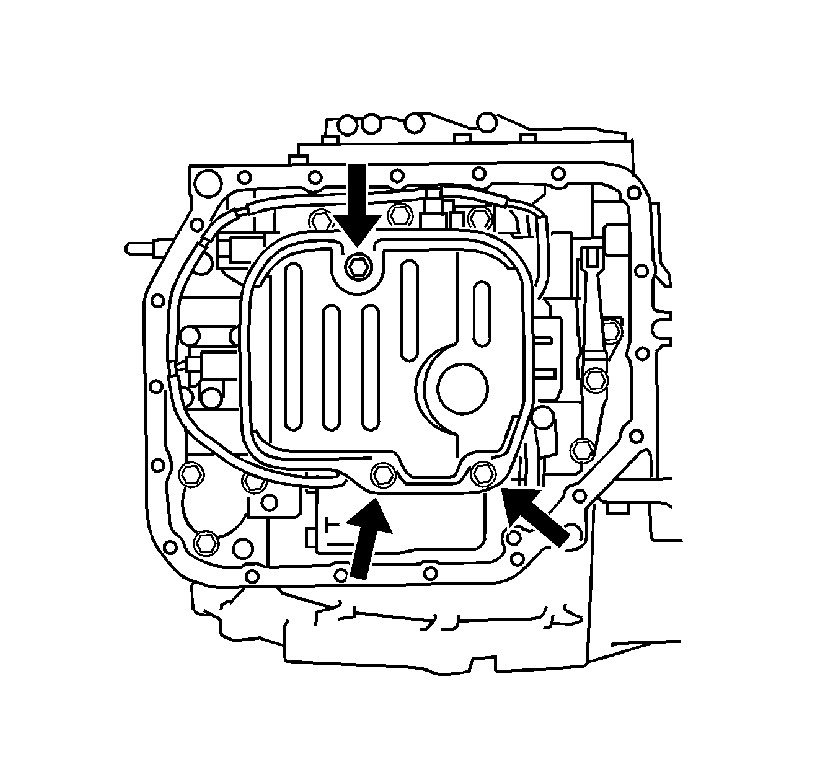
- Install the valve body oil filter and 3 bolts.
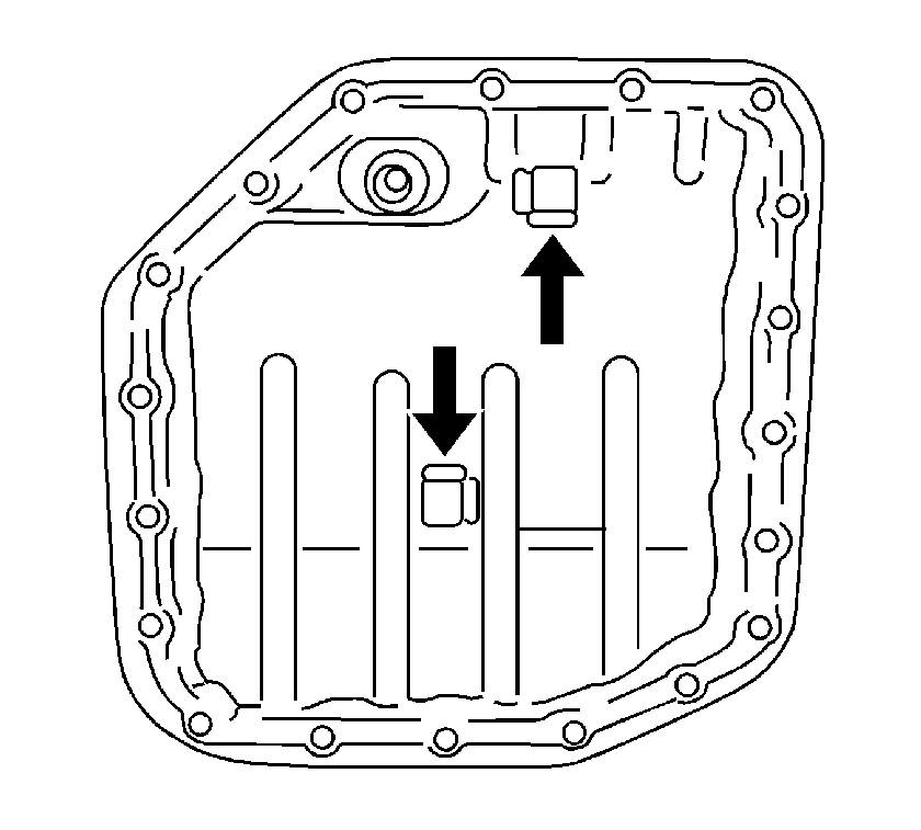
- Install a new oil pan gasket on the oil pan.
- Install the 2 magnets in the oil pan.
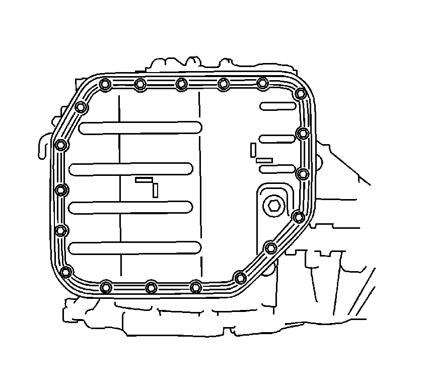
- Install the oil pan on the transaxle case.
- Install the 19 bolts.
- Coat the 4 O-rings for the transaxle case plugs with T-IV automatic transmission fluid, then install the O-rings to the case plugs.
- Install the case plugs into the transaxle case.
- Coat the O-ring for the oil cooler pipe inlet union with T-IV automatic transmission fluid, then install the O-ring to the union.
- Install the oil cooler pipe inlet union.
- Coat the O-ring for the oil cooler pipe outlet union with T-IV automatic transmission fluid, then install the O-ring to the union.
- Install the oil cooler pipe outlet union.
- Install the breather hose.
- Install the input turbine sensor and bolt in the transaxle case.
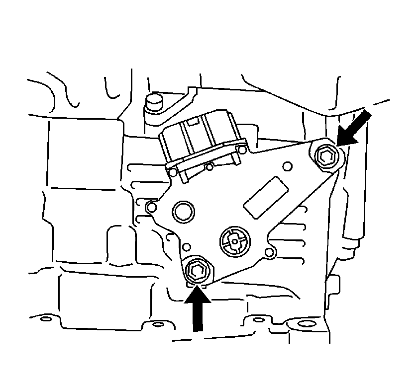
- Install the PNP switch on the manual valve lever shaft, then temporarily install the 2 adjusting bolts.
- Install a new lock washer and nut.
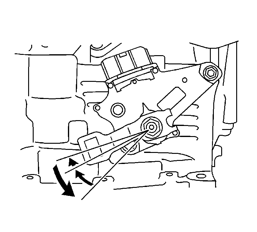
- Temporarily install the control lever.
- Turn the lever counterclockwise until it stops, then turn it clockwise 2 notches.
- Remove the control lever.
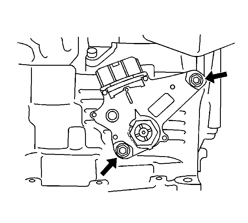
- Align the groove with the neutral base line.
- Tighten the 2 PNP switch bolts.
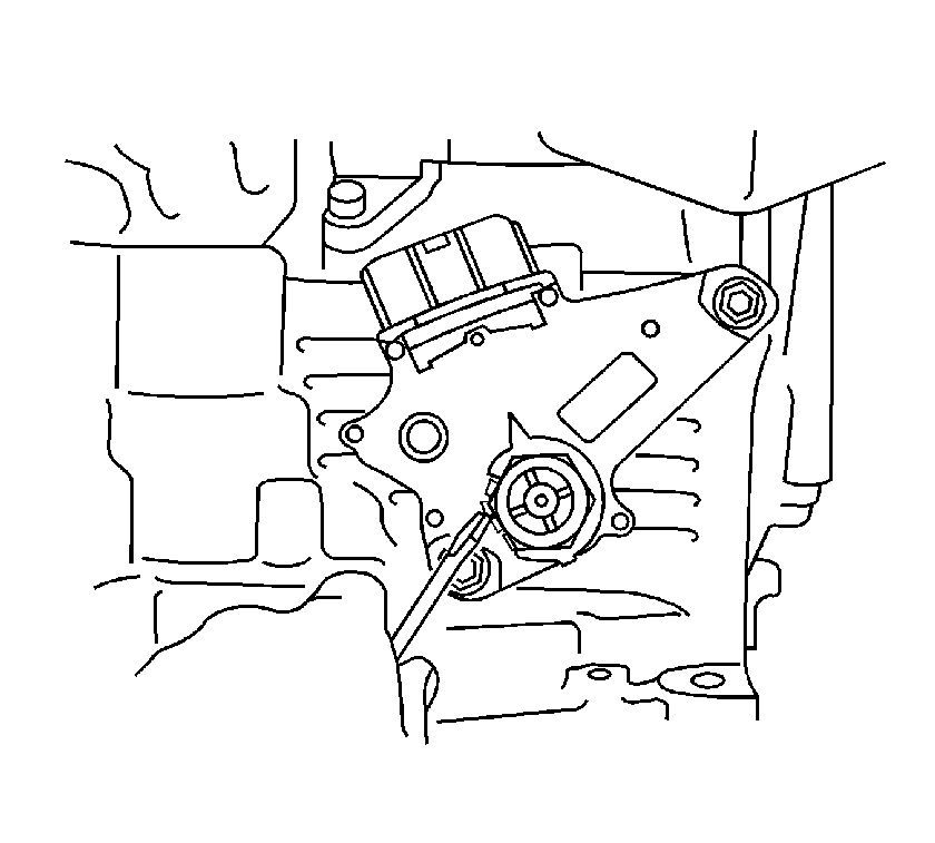
- Using a screwdriver, stake the nut with the lock washer.
- Install the control lever, washer and nut.
- Install the speedometer drive hole cover and bolt on the transaxle case.
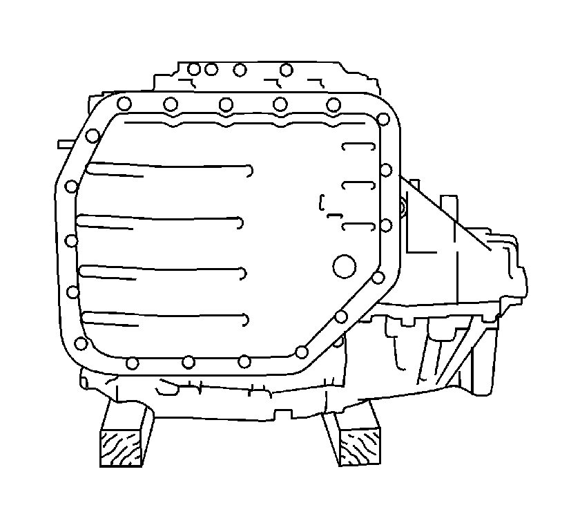
Important: Do not turn the transaxle over to remove the oil pan as it will contaminate the valve body with foreign material within the oil pan.
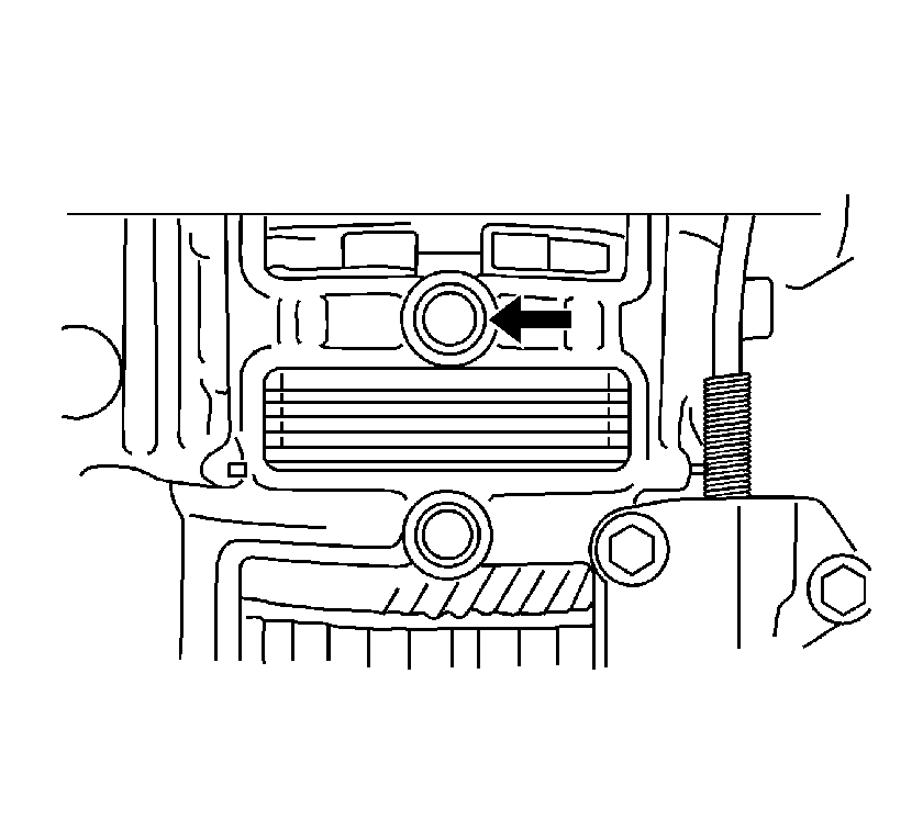
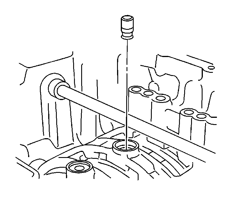
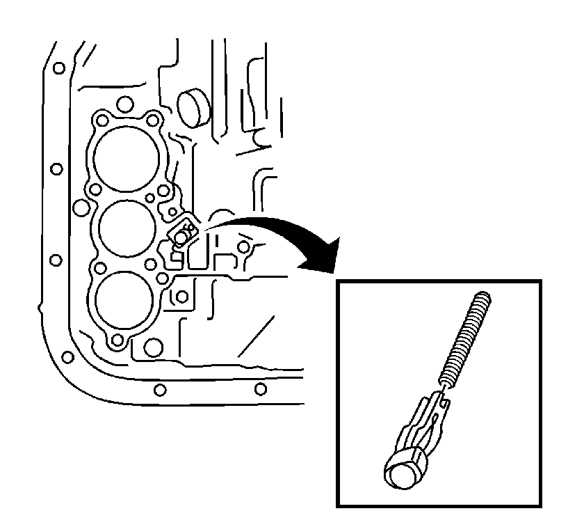
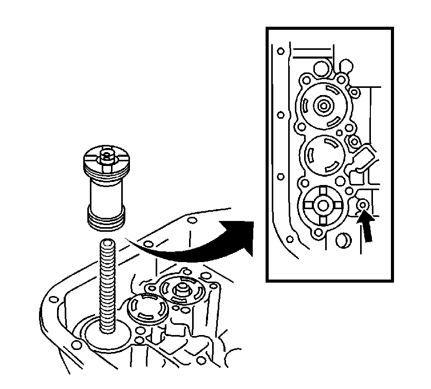
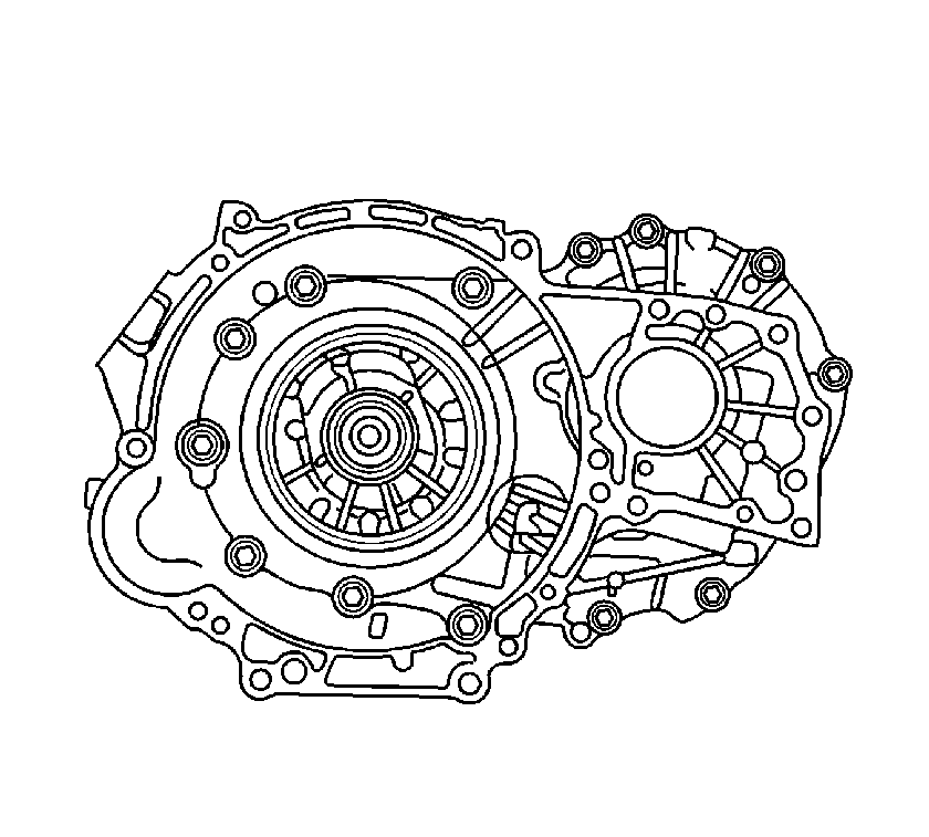
Important: Remove the transaxle housing slowly so the differential gear does not drop out of the transaxle case.
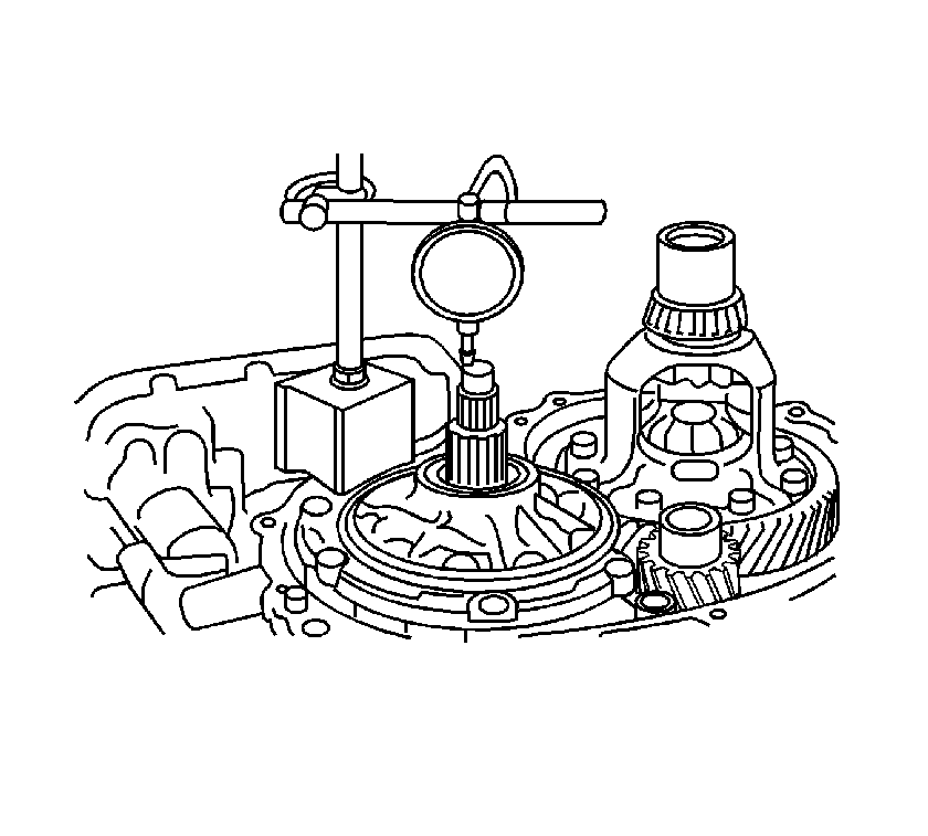
Important: If the end play is not within 0.37-1.29 mm (0.0146-0.0508 in), replace the thrust roller bearing.
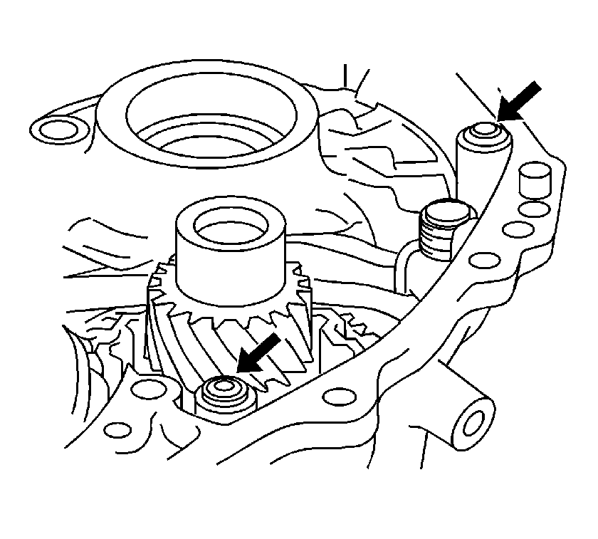
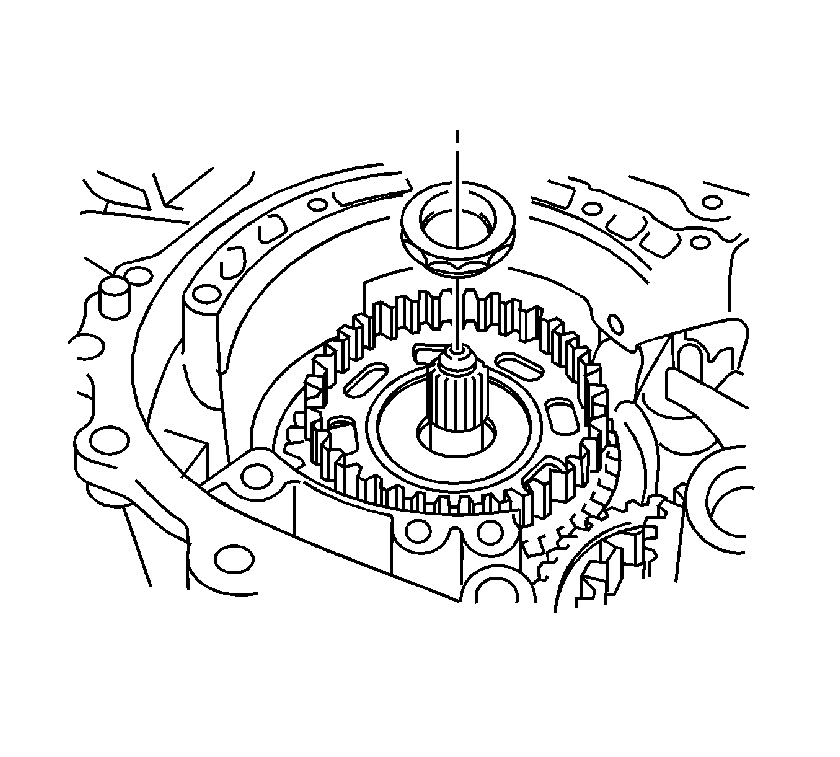
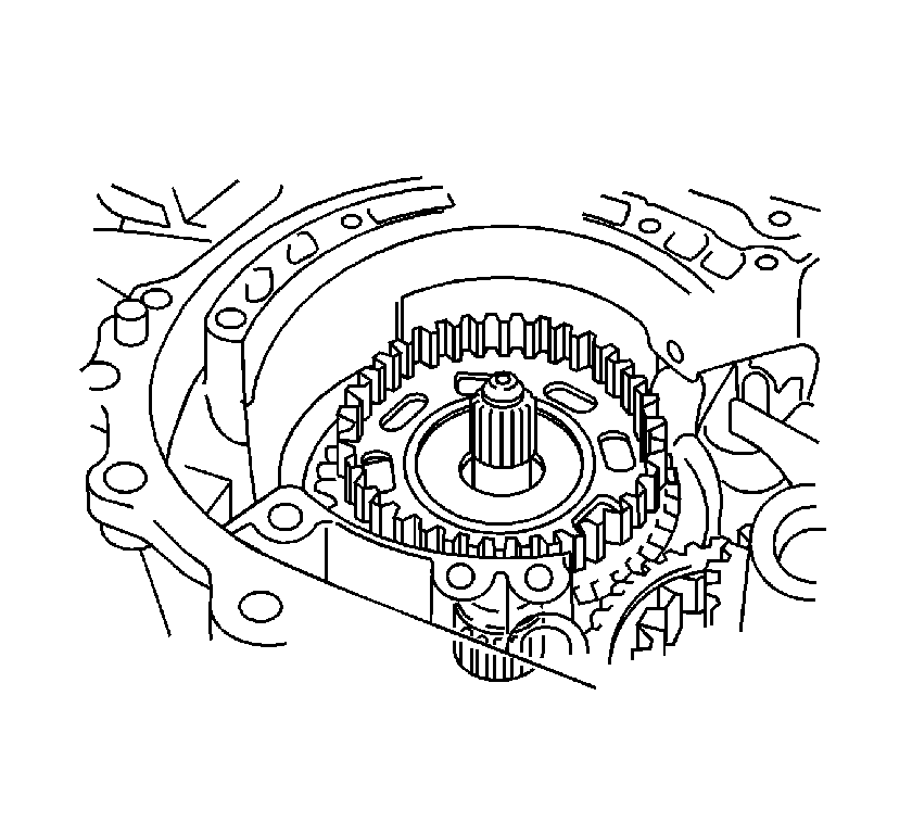
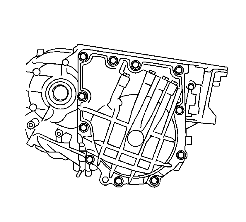
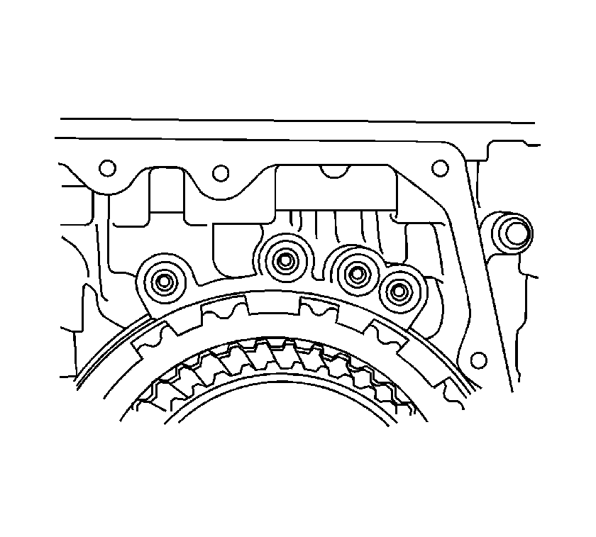
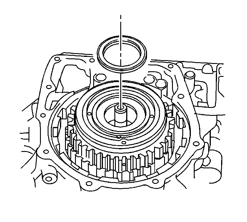
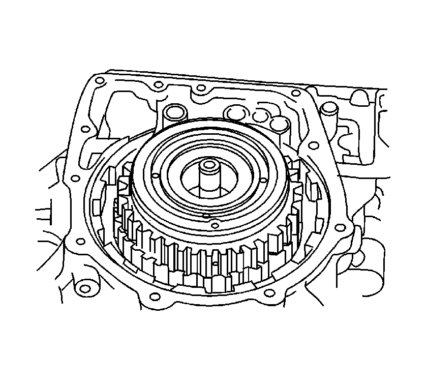
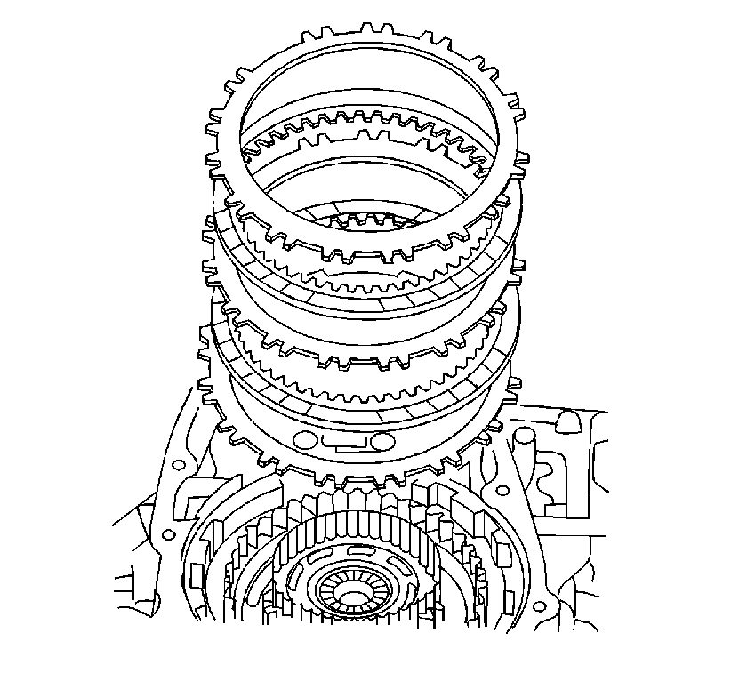
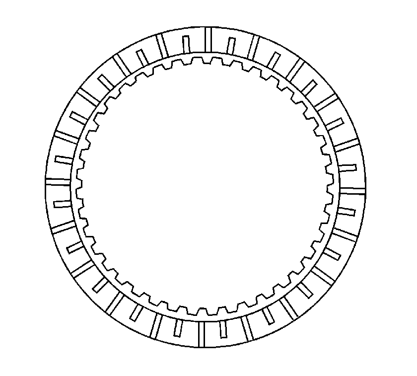
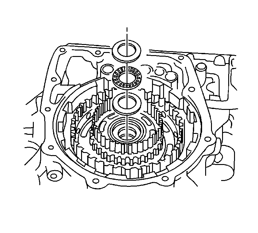
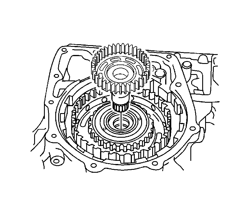
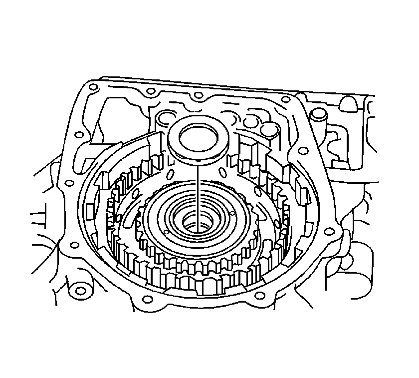
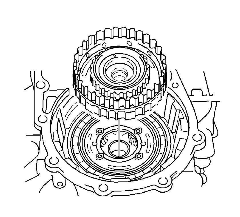

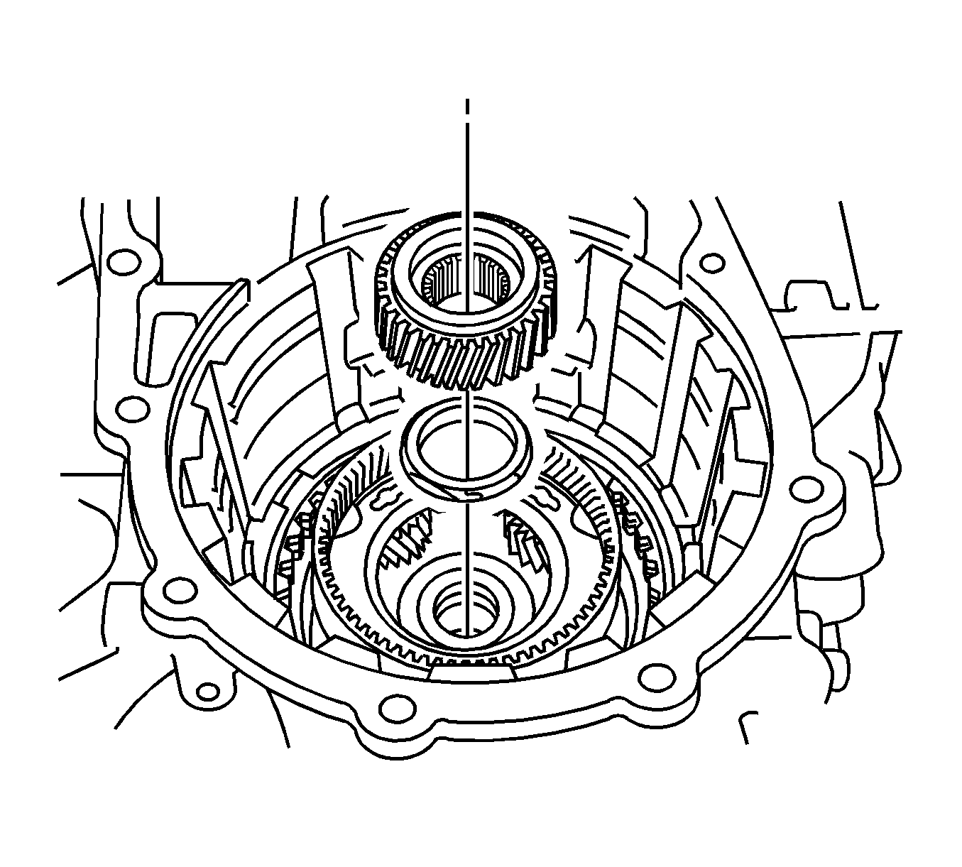
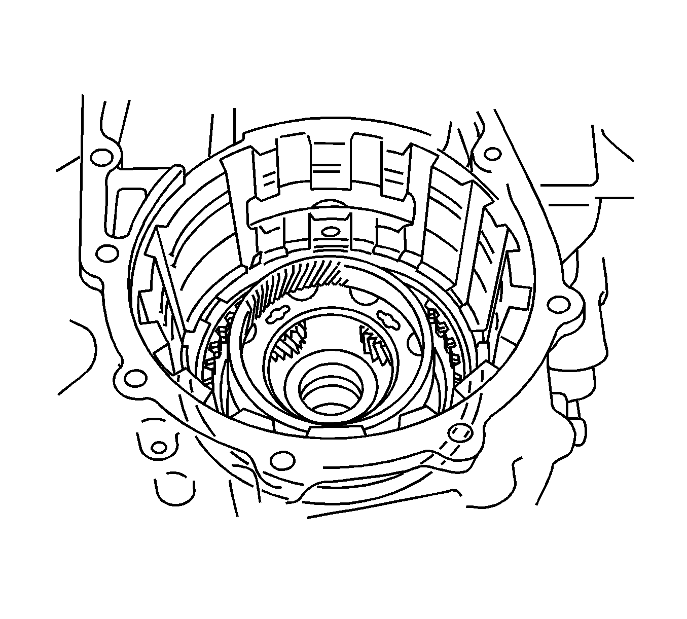
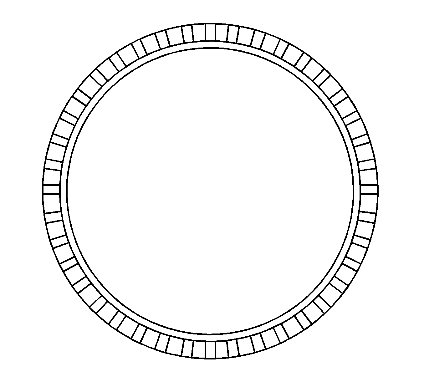
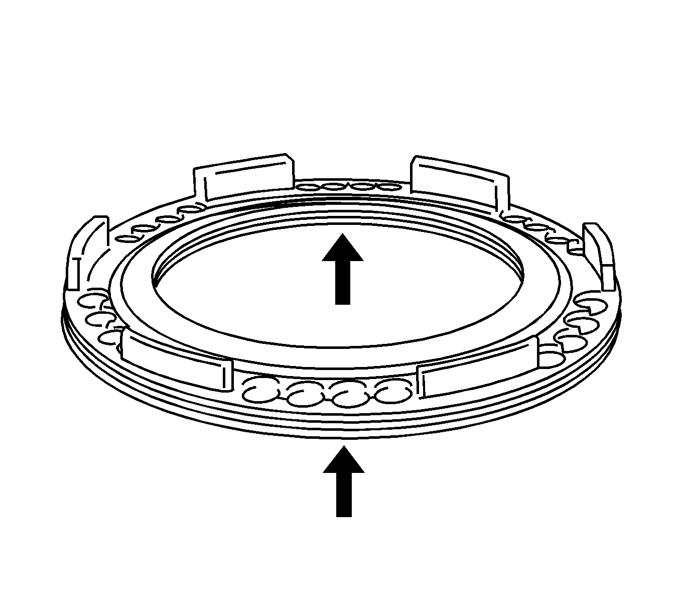
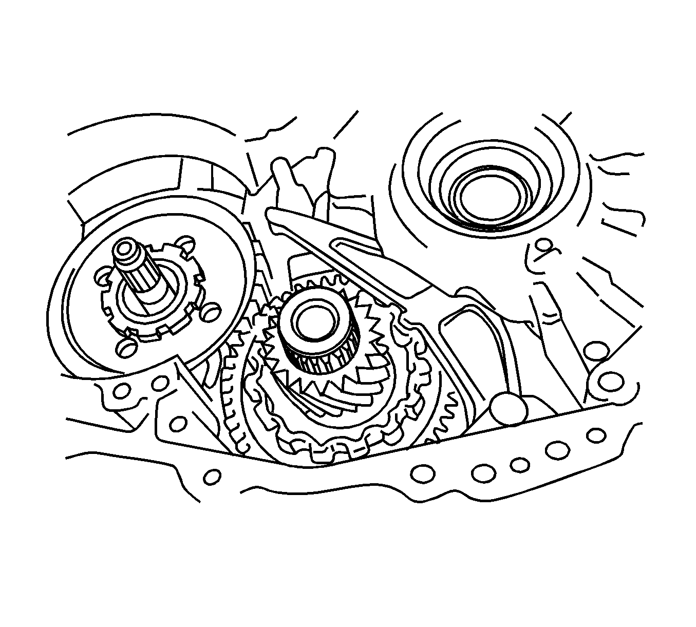
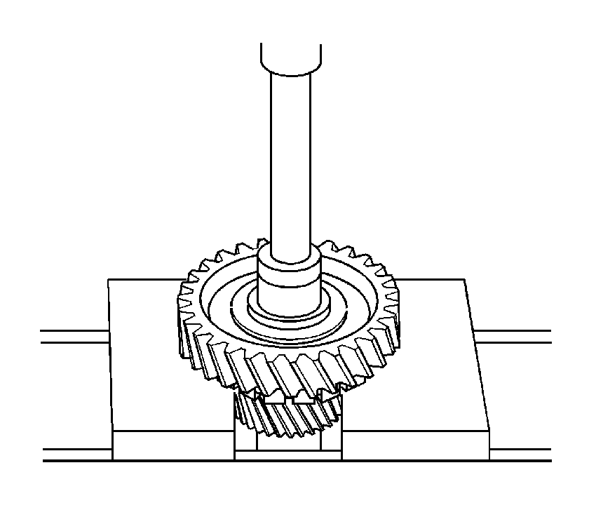
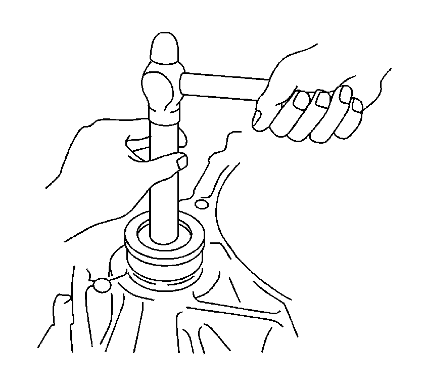
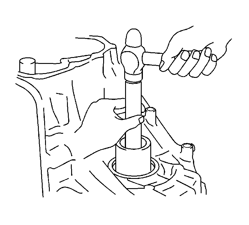
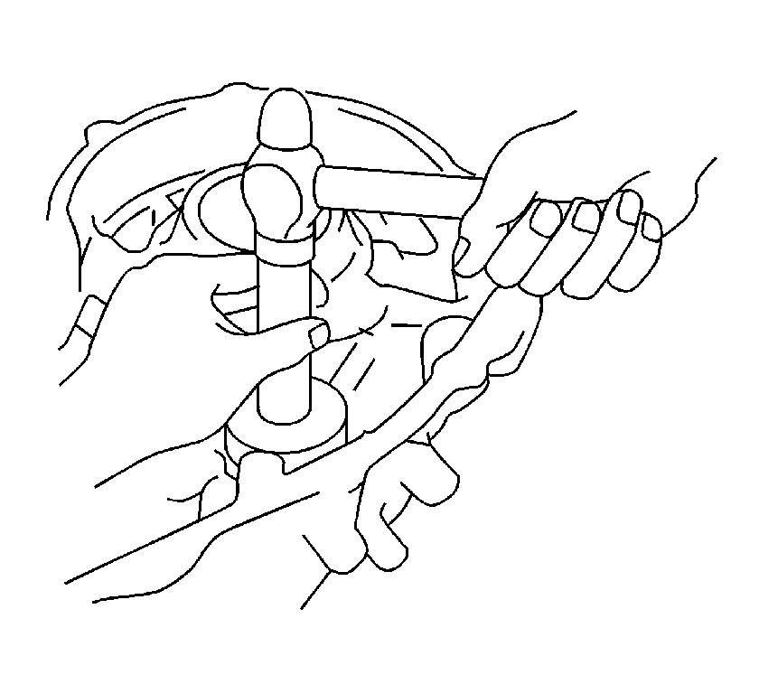

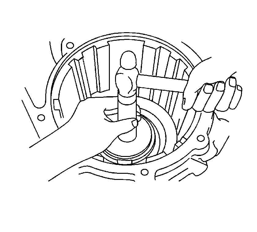
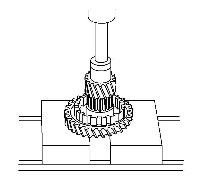
Important: The differential drive pinion should be press fit until it comes in contact with the counter driven gear.
Important: The plug should be installed to a depth of 2.5-2.6 mm (0.0984-0.1023 in).
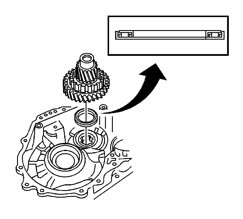

Notice: Refer to Fastener Notice in the Preface section.
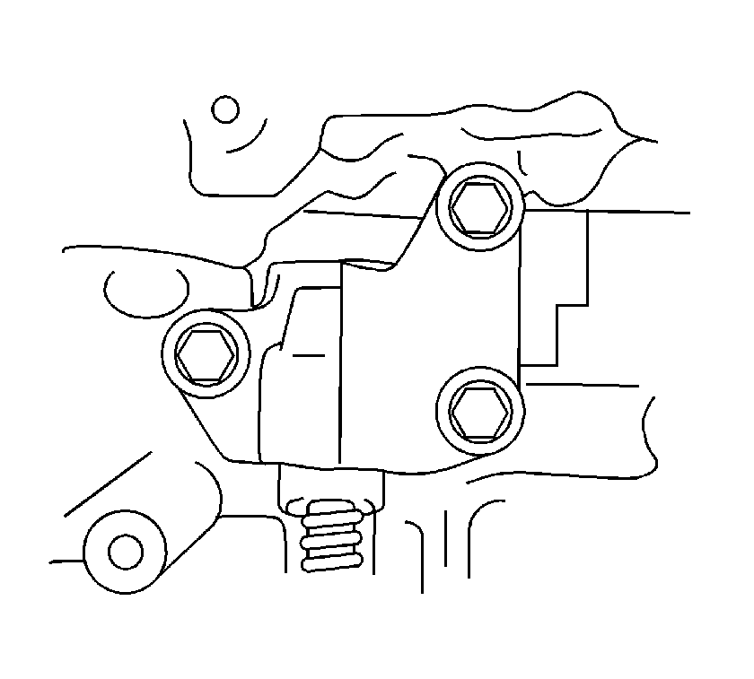
Tighten
Tighten the bolts to 20 N·m (15 lb ft).
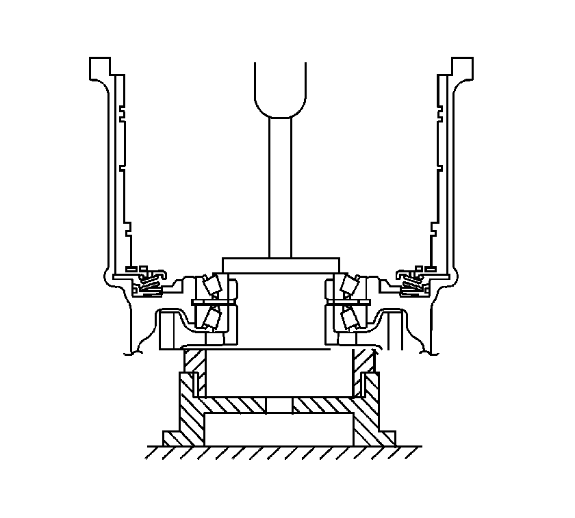
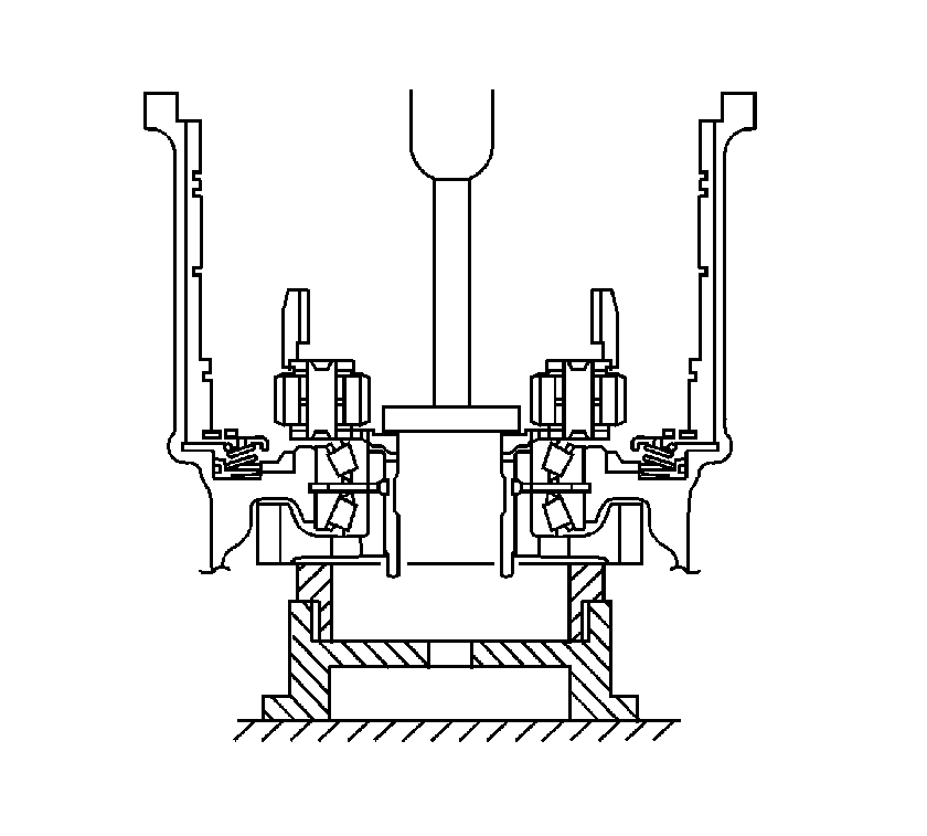
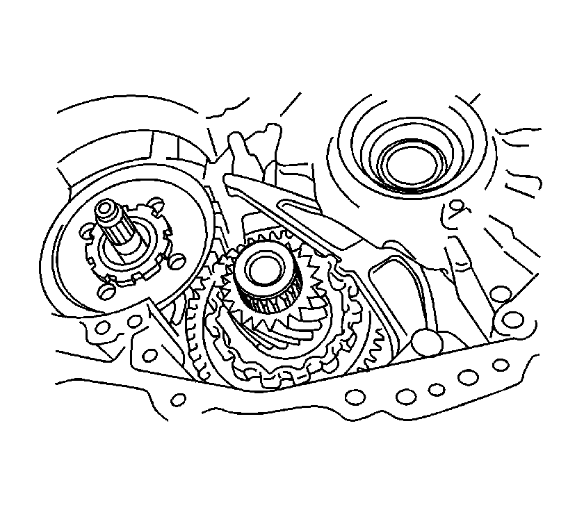
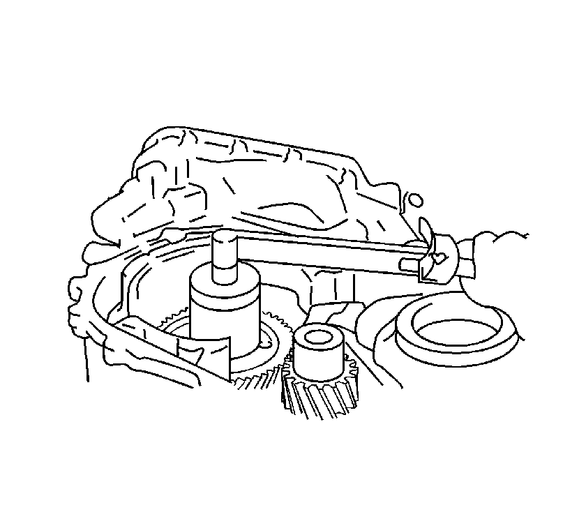
Tighten
Tighten the nut to 280 N·m (207 lb ft).
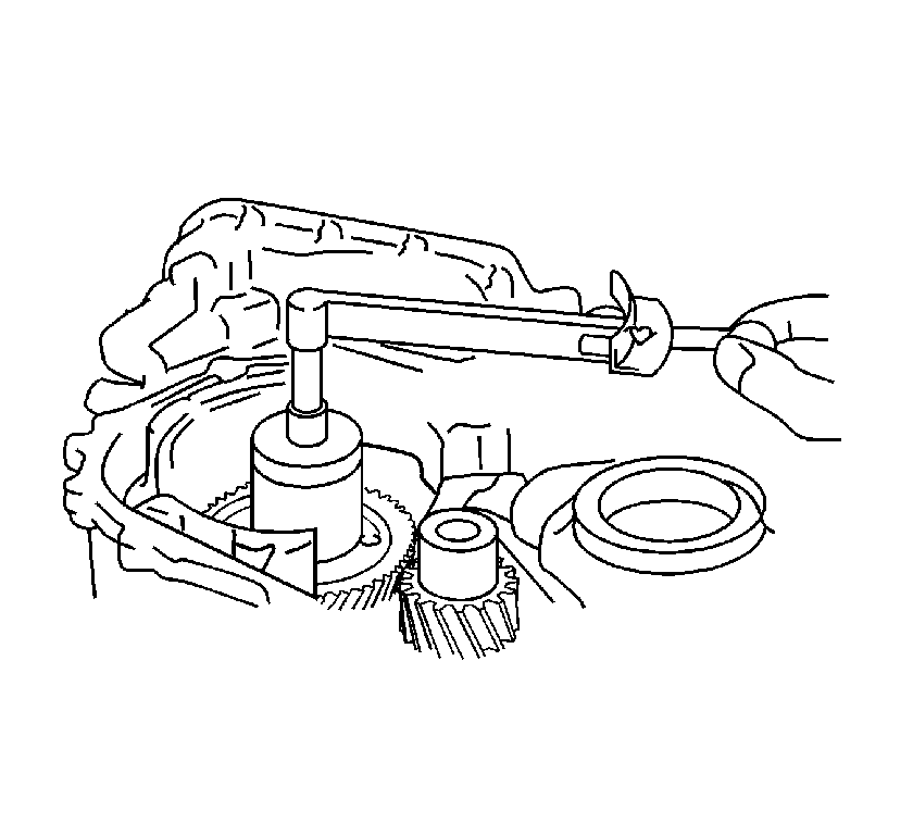
Rotating Torque
Rotating torque should be 0.20-0.49 N·m
(2-4 lb in).
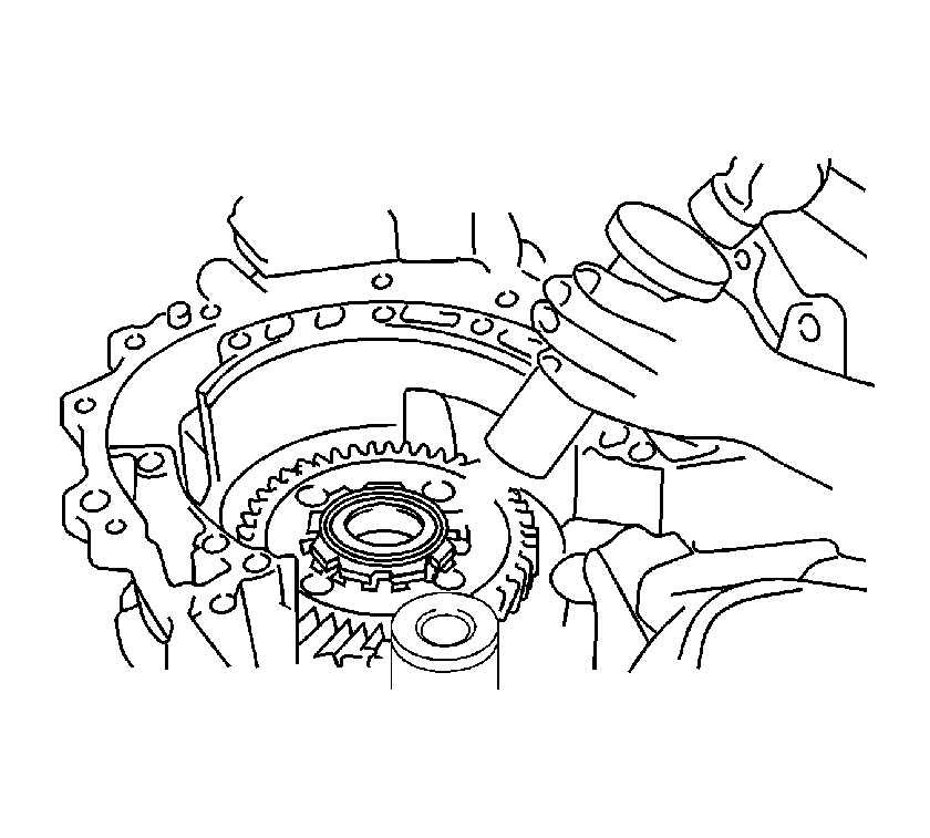
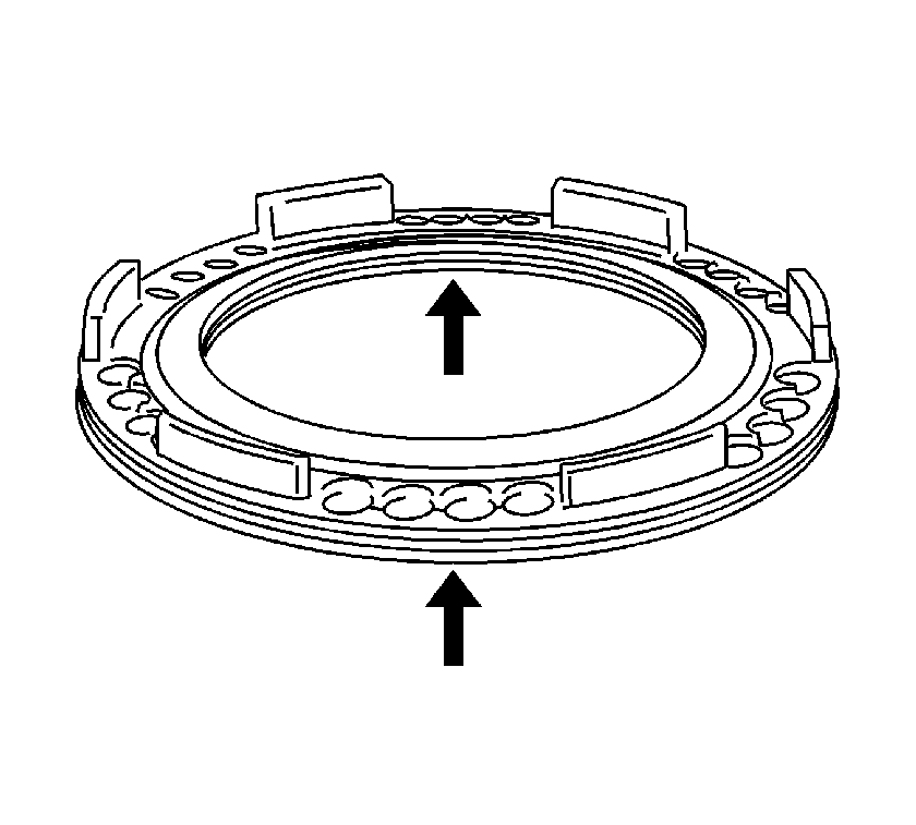
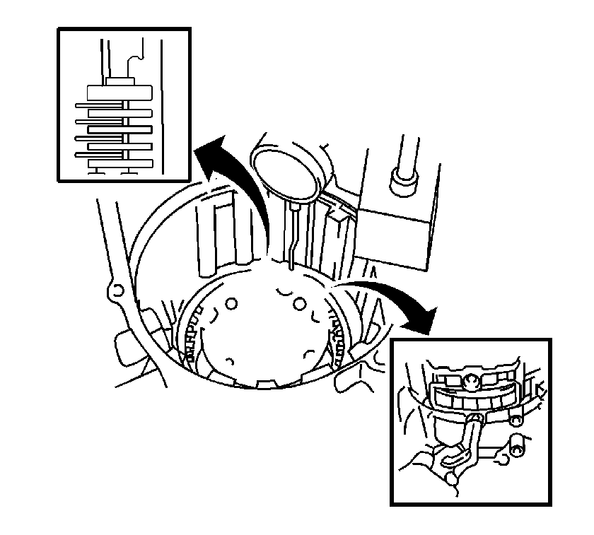
Important: While applying 392 kPa (57 psi) of compressed air, measure the pack clearance. The pack clearance should be within 0.806-1.206 mm (0.0317-0.0475 in). If the pack clearance is not as specified, install a new flange.
There are 4 thicknesses available, 3.4 mm (0.134 in), 3.6 mm (0.142 in), 3.8 mm (0.150 in), 4.0 mm (0.157 in).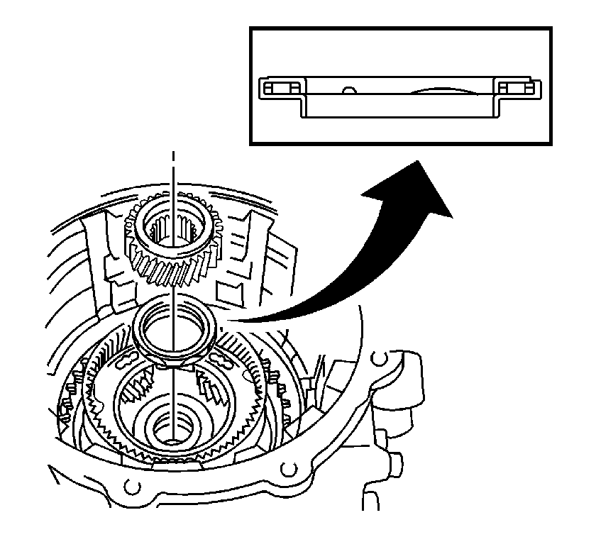

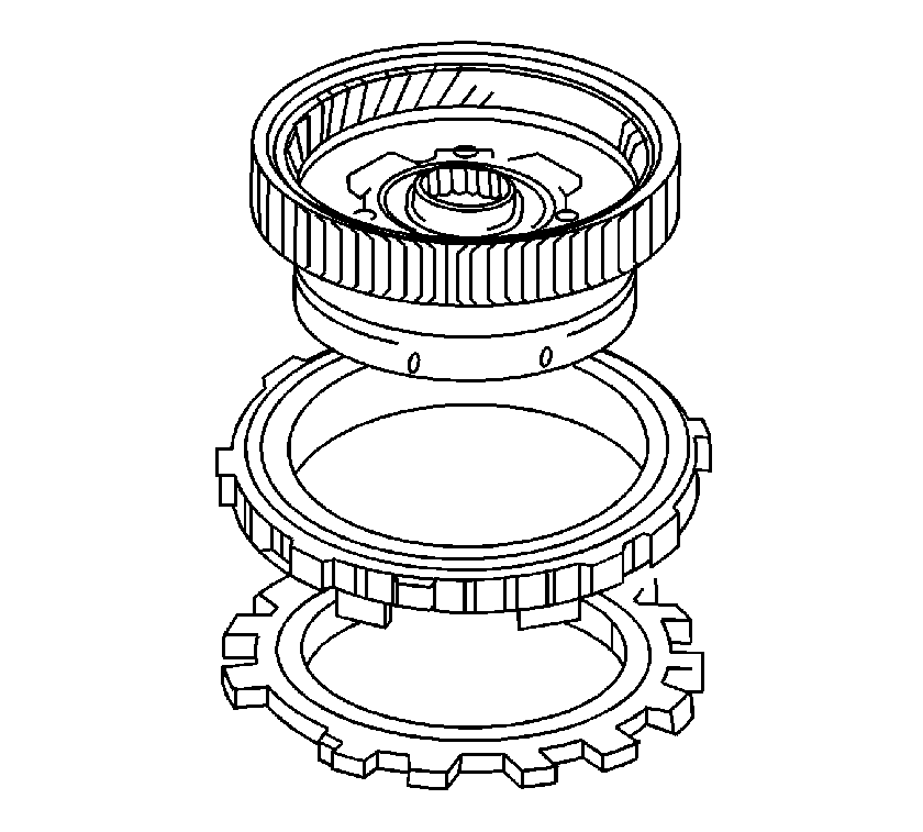
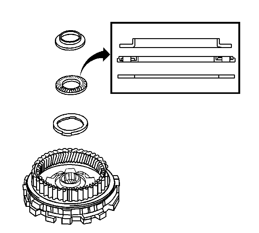
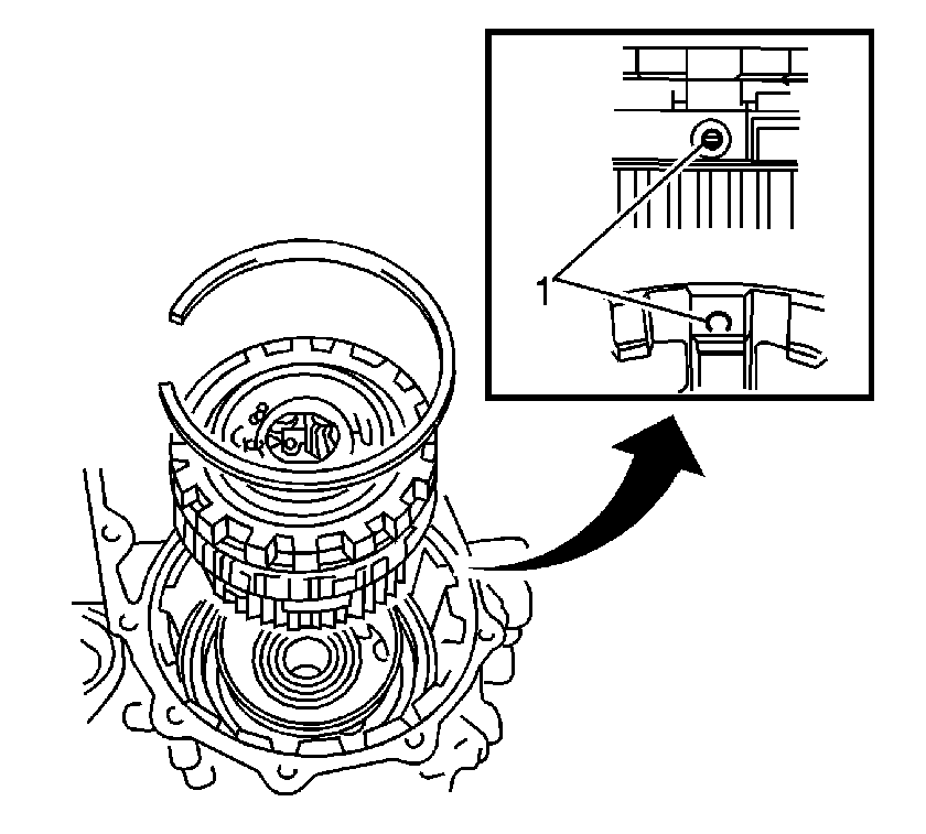
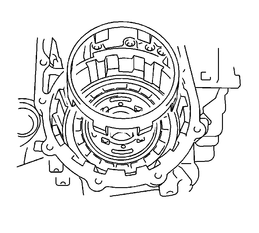
Important: Align the oil hole (1) of the 2nd brake piston assembly with the oil hole (1) in the transaxle case, then install the assembly into the transaxle case.
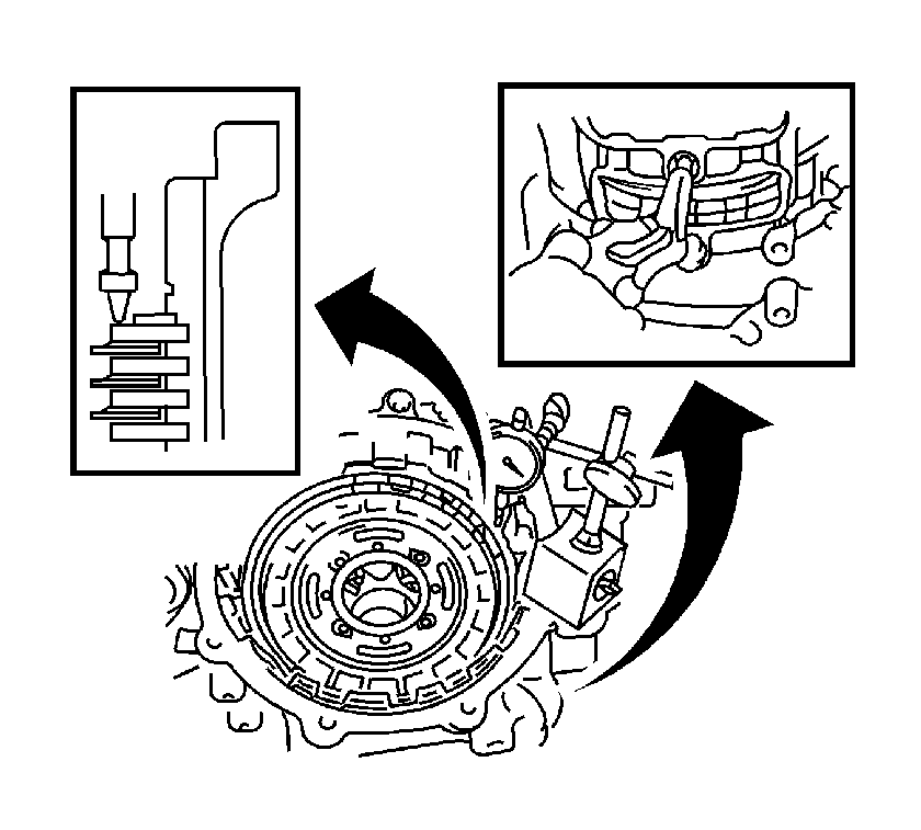
Important: While applying 392 kPa (57 psi) of compressed air, measure the pack clearance. The pack clearance should be within 0.847-1.247 mm (0.0333-0.0491 in). If the pack clearance is not as specified, install a new flange.
There are 4 thicknesses available, 3.0 mm (0.118 in), 3.2 mm (0.126 in), 3.4 mm (0.134 in), 3.6 mm (0.142 in).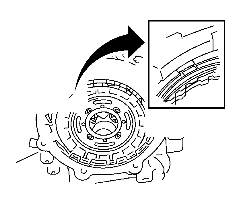
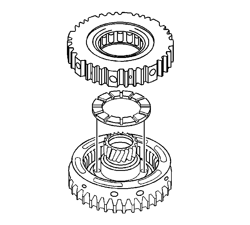

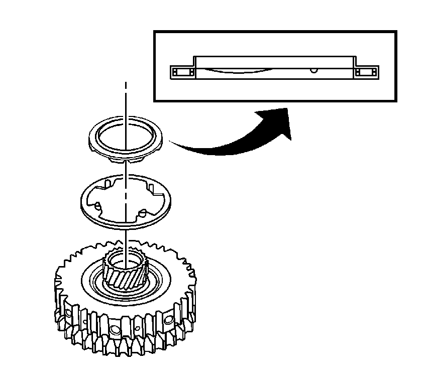
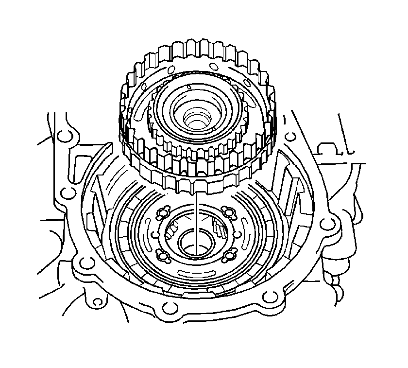
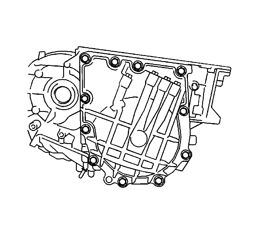
Tighten
Tighten the 11 bolts to 24.5 N·m
(18 lb ft).
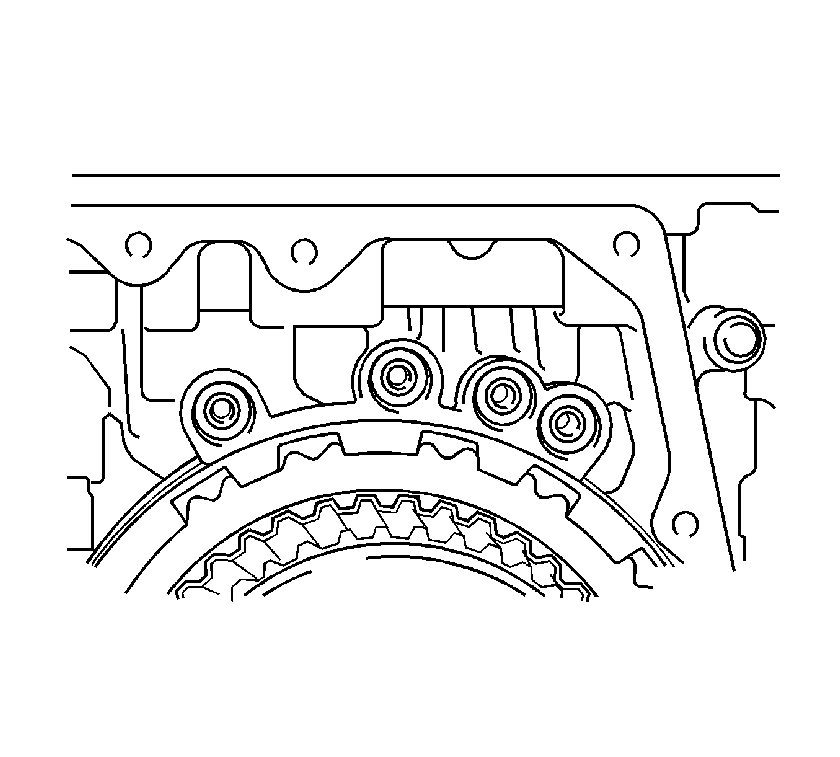
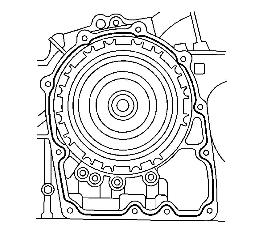

Tighten
Tighten the 11 bolts to 24.5 N·m
(18 lb ft).
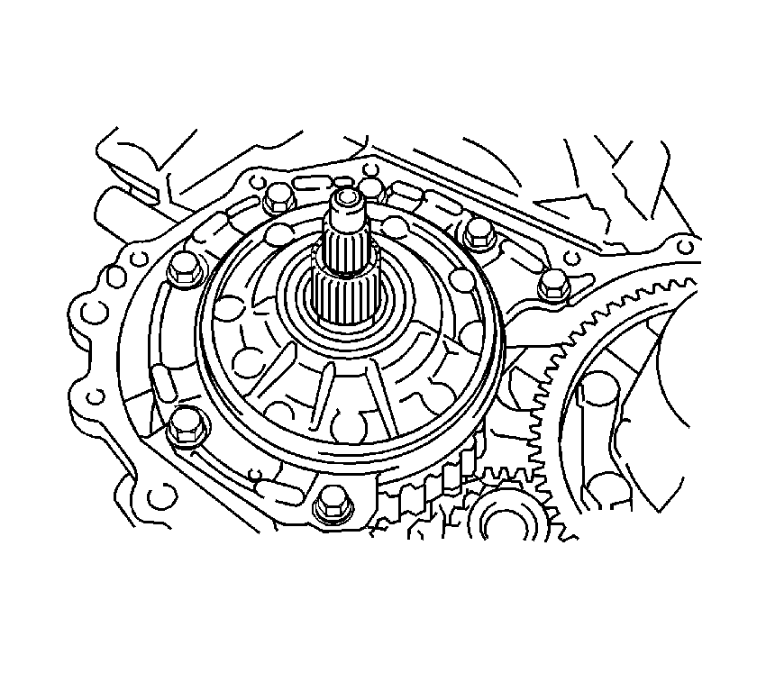
Tighten
Tighten the bolts to 22 N·m (16 lb ft).
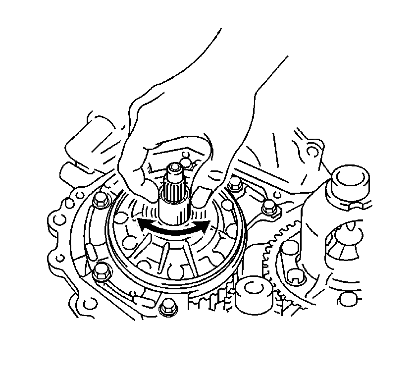

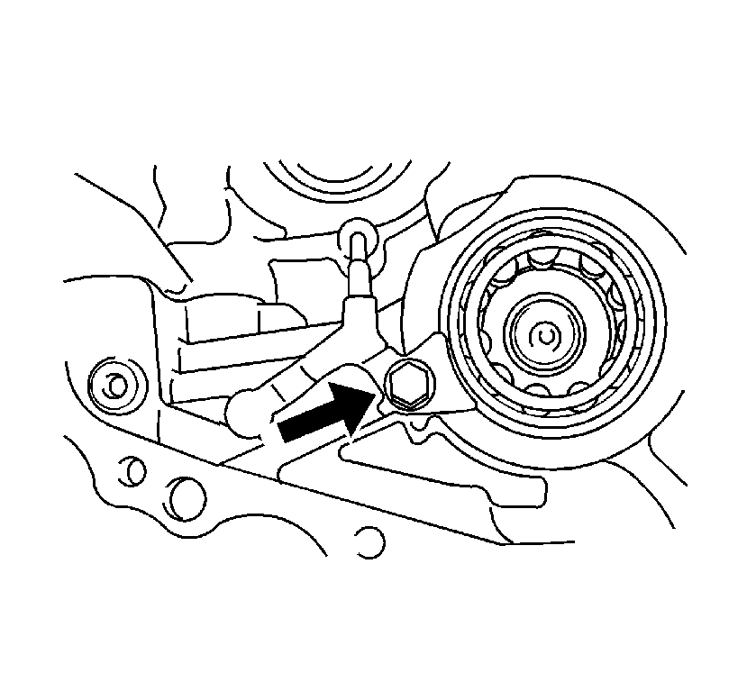
Tighten
Tighten the bolt to 11 N·m (8 lb ft).
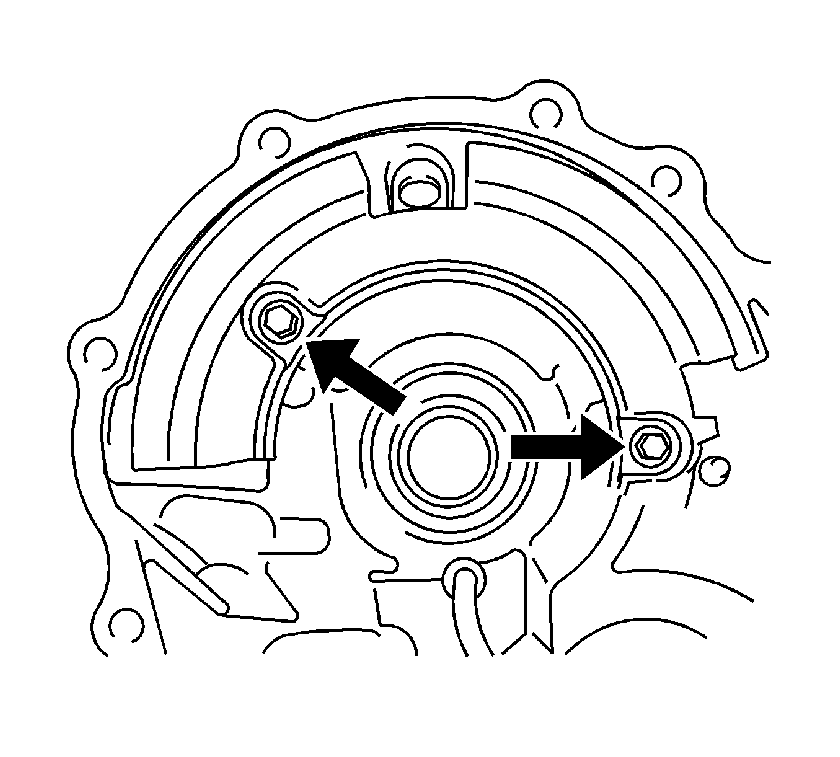
Tighten
Tighten the bolts to 10 N·m (7 lb ft).
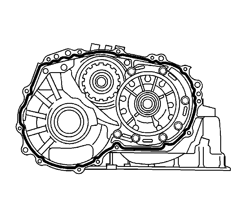
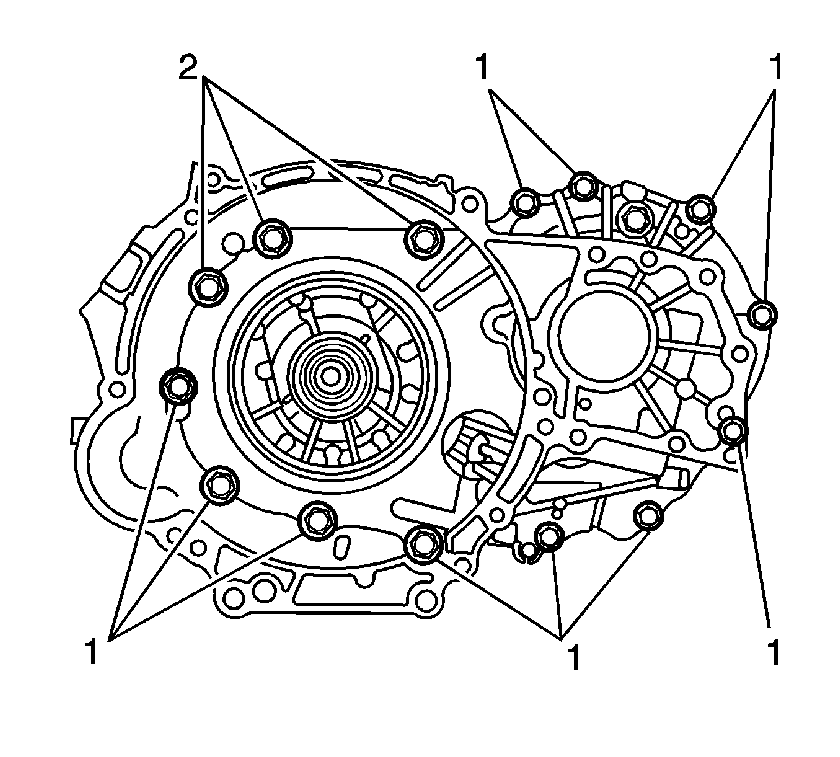
Tighten
| • | Tighten the bolts (1) to 29 N·m (21 lb ft). |
| • | Tighten the bolts (2) to 22 N·m (16 lb ft). |
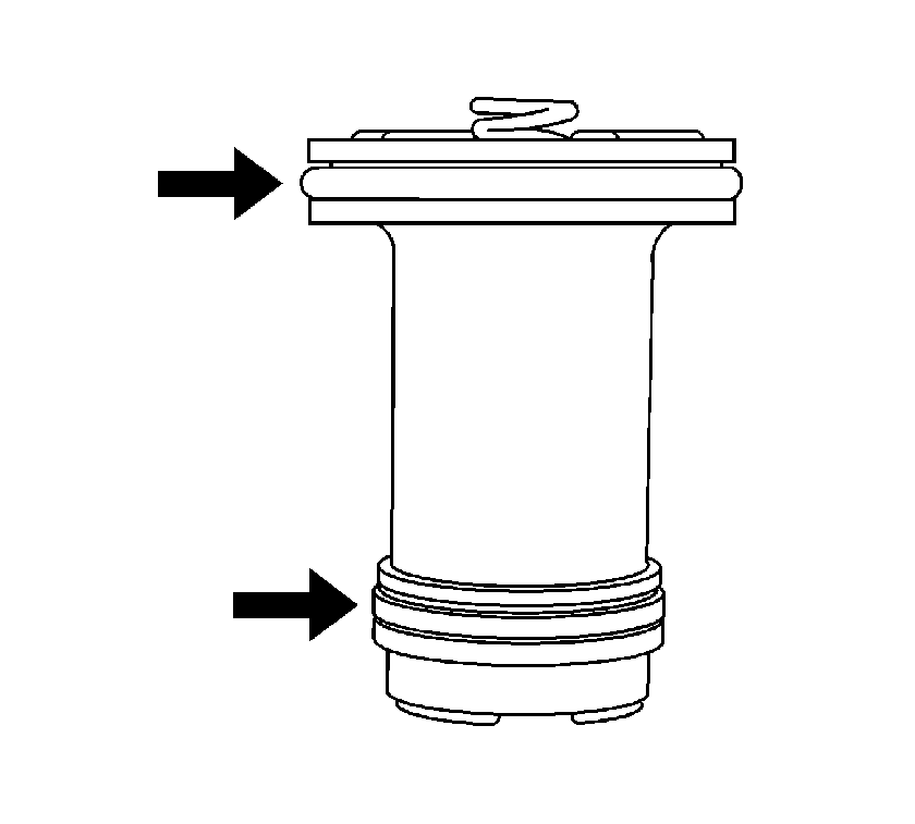
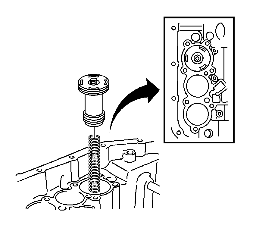
Important: Inspect the C2 accumulator piston spring. The free length is 66.90 mm (2.6339 in). The outer diameter is 17.20 mm (0.6772 in). If the spring is not as specified, replace the spring.
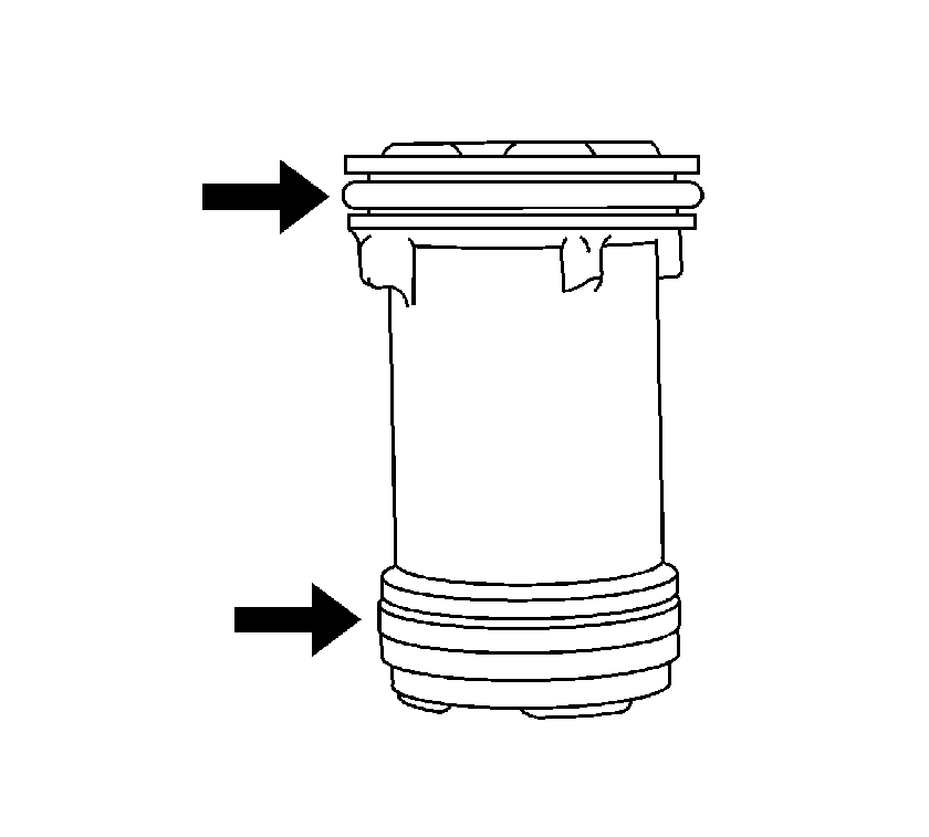
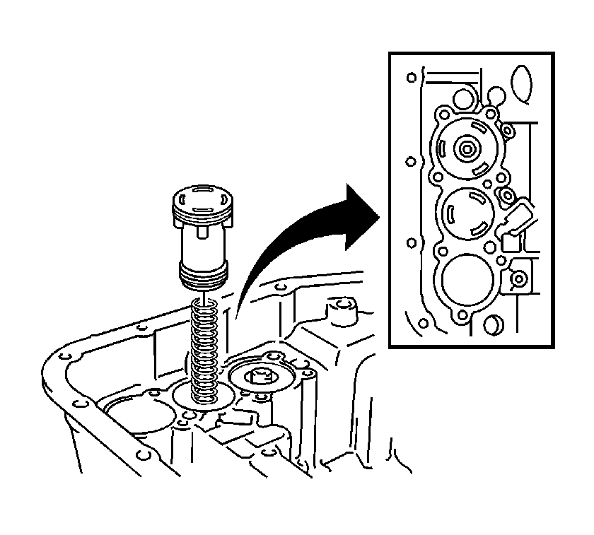
Important: Inspect the C3 accumulator piston spring which is blue in color. The free length is 80.20 mm (3.1575 in). The outer diameter is 18.70 mm (0.7362 in). If the spring is not as specified, replace the spring.
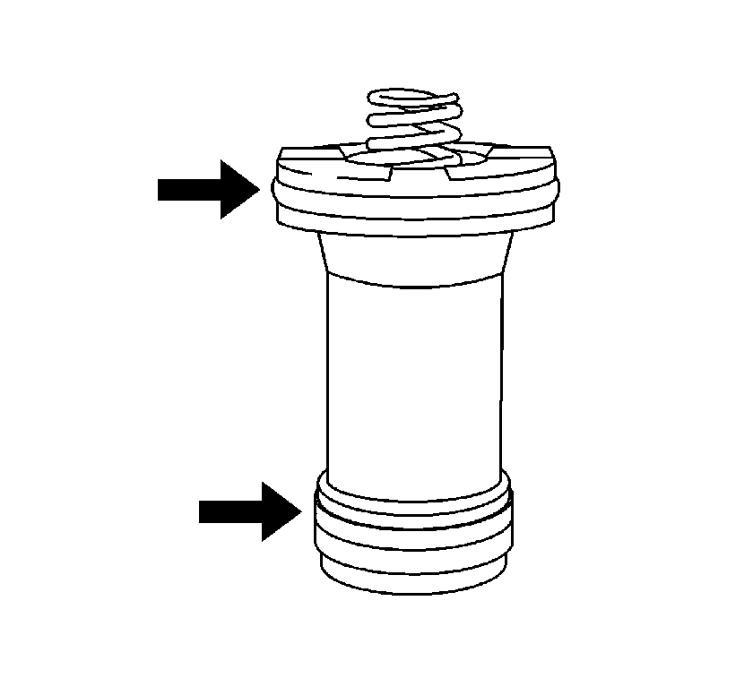
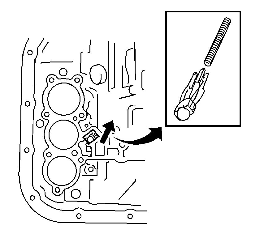
Important: Inspect the B2 accumulator piston spring which is green in color. The free length is 66.90 mm (2.6339 in). The outer diameter is 15.50 mm (0.6102 in). If the spring is not as specified, replace the spring.
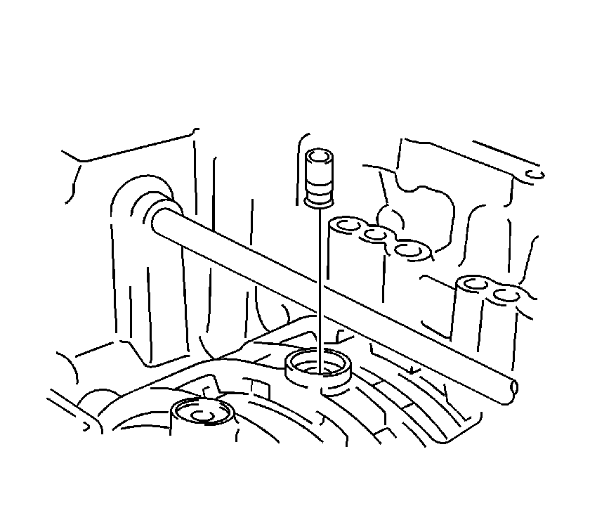
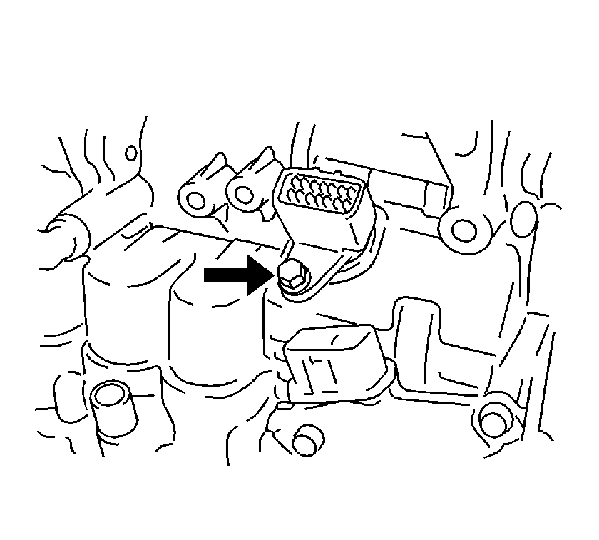
Tighten
Tighten the bolt to 5.5 N·m (48 lb in).
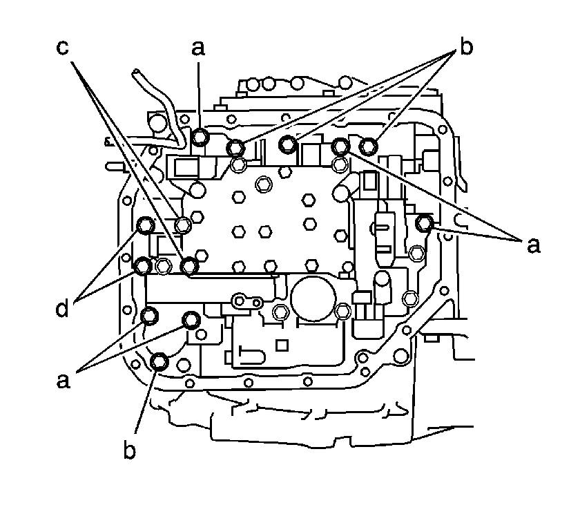
| • | Bolt (a) length is 32 mm (1.26 in) |
| • | Bolt (b) length is 22 mm (0.87 in) |
| • | Bolt (c) length is 55 mm (2.17 in) |
| • | Bolt (d) length is 45 mm (1.77 in) |
Tighten
Tighten the 13 bolts to 11 N·m
(8 lb ft).
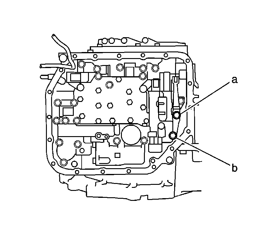
| • | Bolt (a) length is 14 mm (0.55 in) |
| • | Bolt (b) length is 45 mm (1.77 in) |
Tighten
Tighten the 2 bolts to 11 N·m
(8 lb ft).
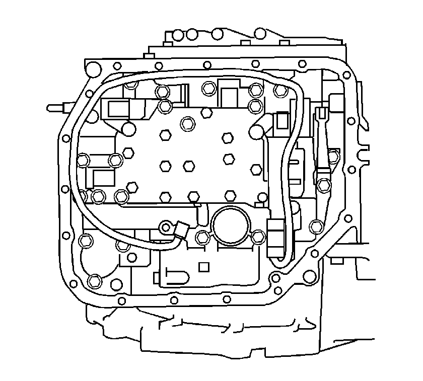
Tighten
Tighten the bolt to 11 N·m (8 lb ft).
Tighten
Tighten the bolts to 11 N·m (8 lb ft).
Tighten
Tighten the bolts to 8 N·m (70 lb in).
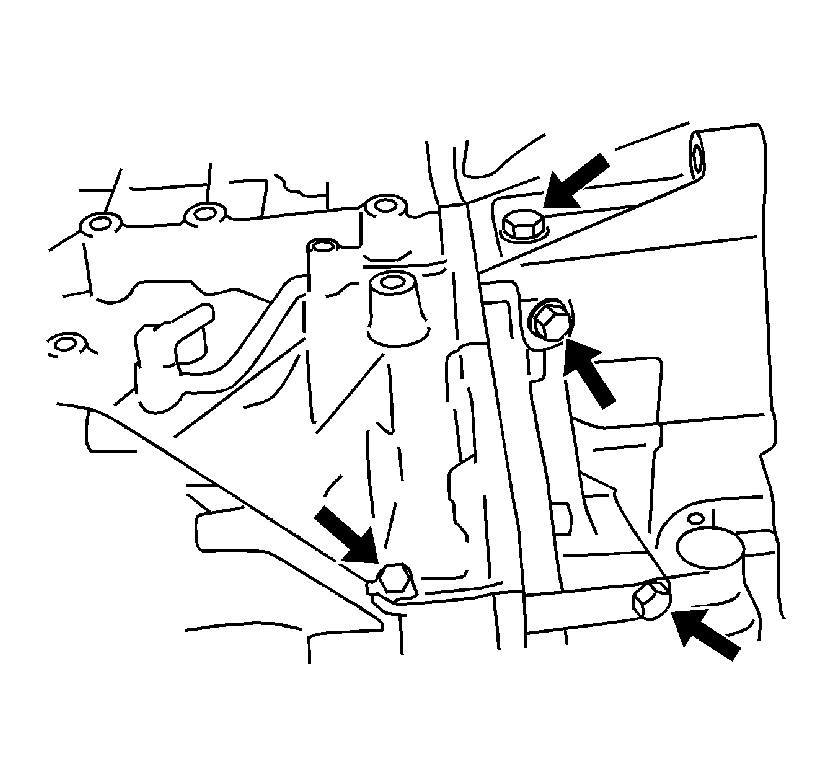
Tighten
Tighten the plugs to 7.4 N·m (65 lb in).
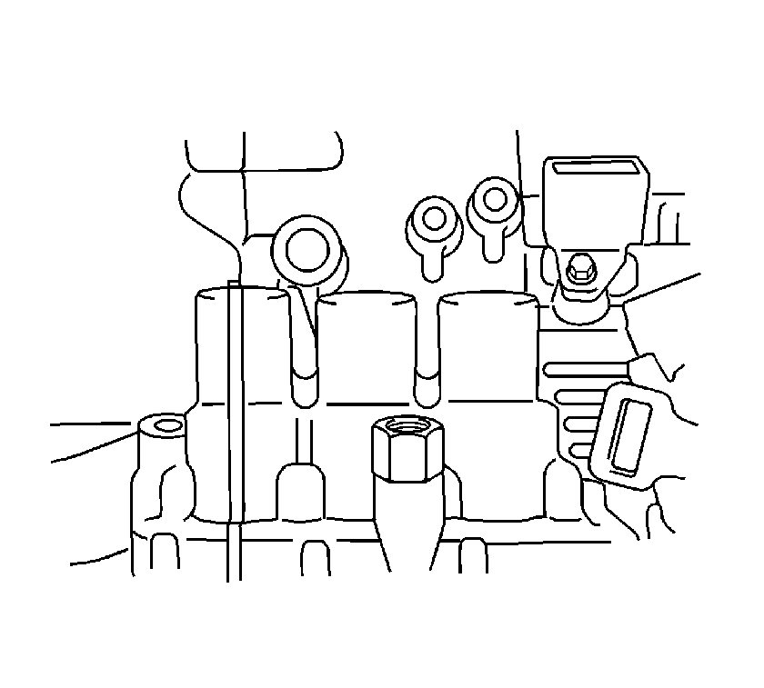
Tighten
Tighten the union to 27 N·m (20 lb ft).
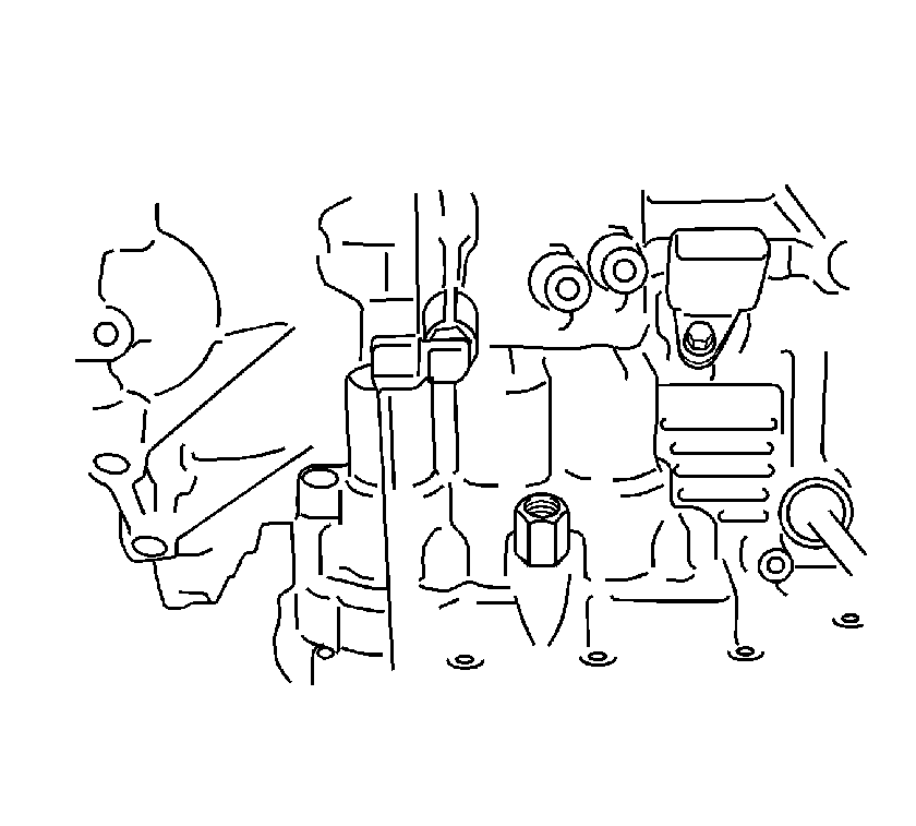
Tighten
Tighten the union to 27 N·m (20 lb ft).
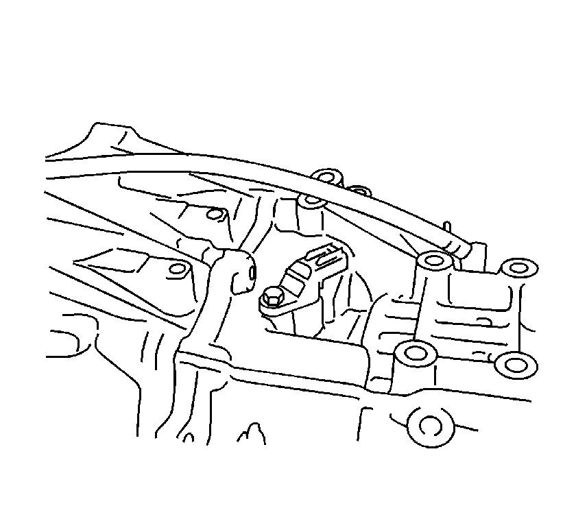
Tighten
Tighten the bolt to 5.4 N·m (48 lb in).
Tighten
Tighten the nut to 6.9 N·m (61 lb in).
Tighten
Tighten the bolts to 5.4 N·m (48 lb in).
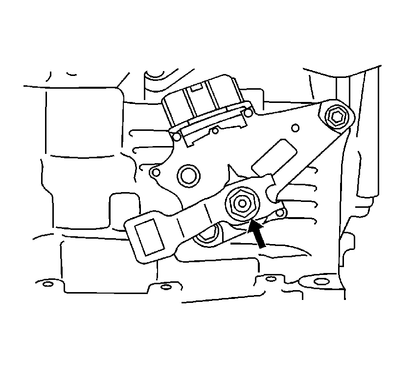
Tighten
Tighten the nut to 13 N·m (10 lb ft).
Tighten
Tighten the bolt to 7 N·m (62 lb in).
