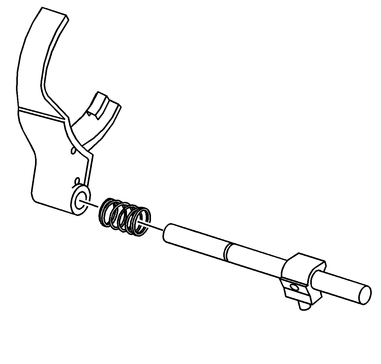
- If disassembled, install the 2/4 shift fork and spring
on the shift shaft.
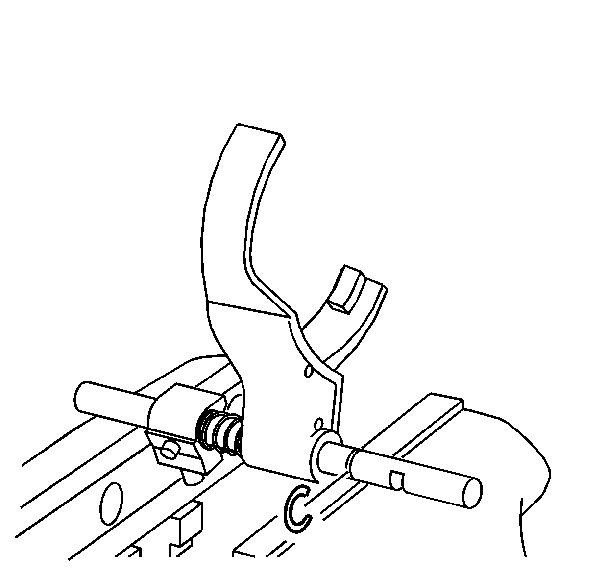
- Compress the spring on the 2/4 shift
fork in a vise.
- Install the retaining ring.
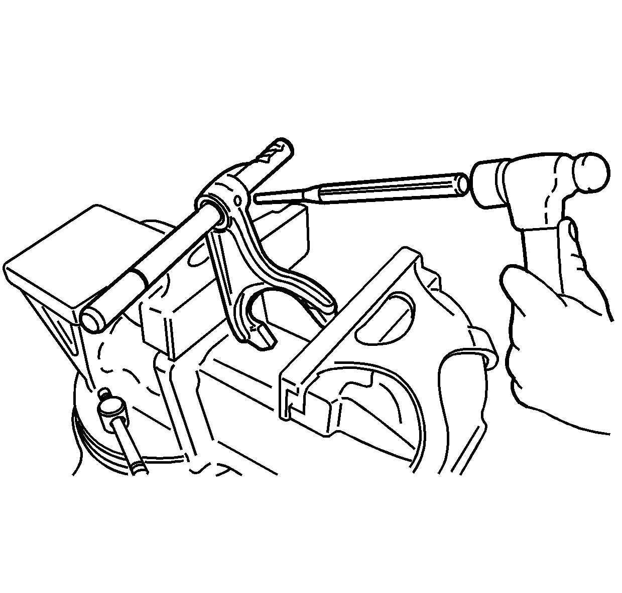
- If disassembled, install the high/low
shift fork on the shift shaft. Position the fork, as shown, on the shift shaft.
- Install the roll pin in the shift fork until flush.
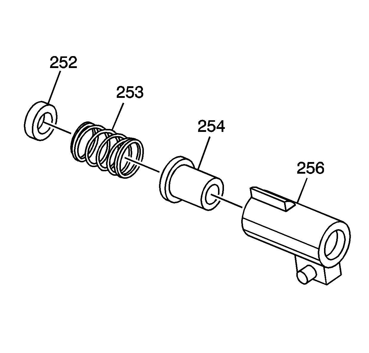
- Install the spring seat (252),
the spring (253) and the block collar (254) in the shift block (256).
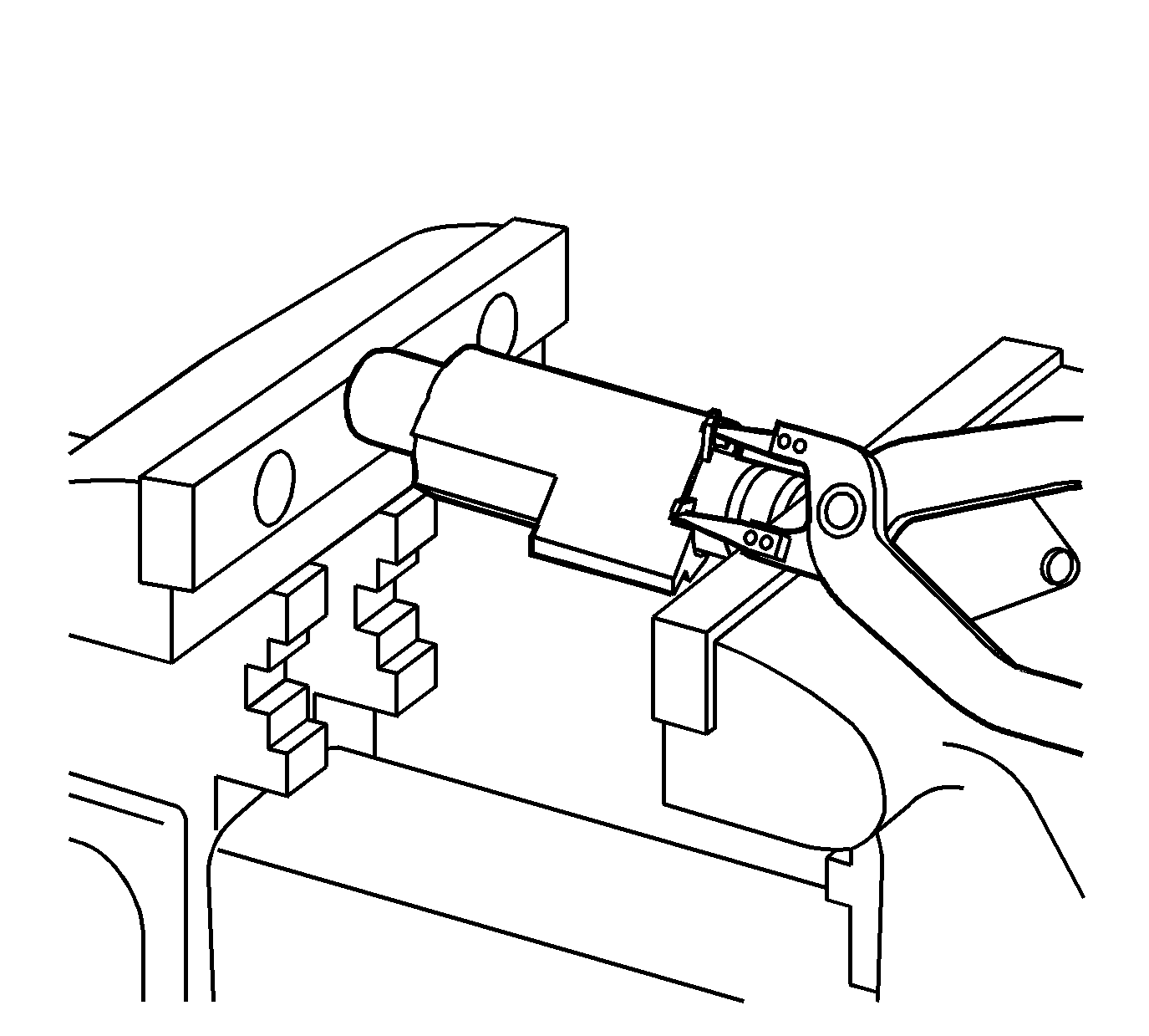
- Install the inner retaining ring over
a socket.
- Install the socket and the block in a vise to compress the spring.
- Install the inner retaining ring in the block.
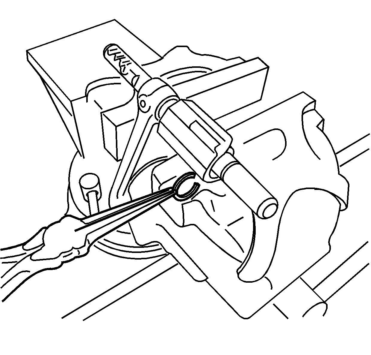
- Using a vise, compress the spring in
the high/low shift block.
- Install the retaining ring on the shift rail.
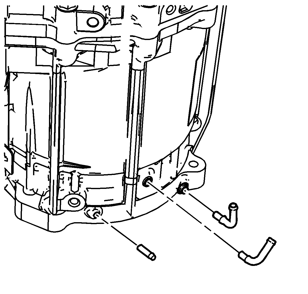
- If removed, using retaining compound GM P/N 12377901
(Canadian P/N 10953504), or equivalent, install the vent or breather hose pipes. Ensure the pipes are properly aligned.
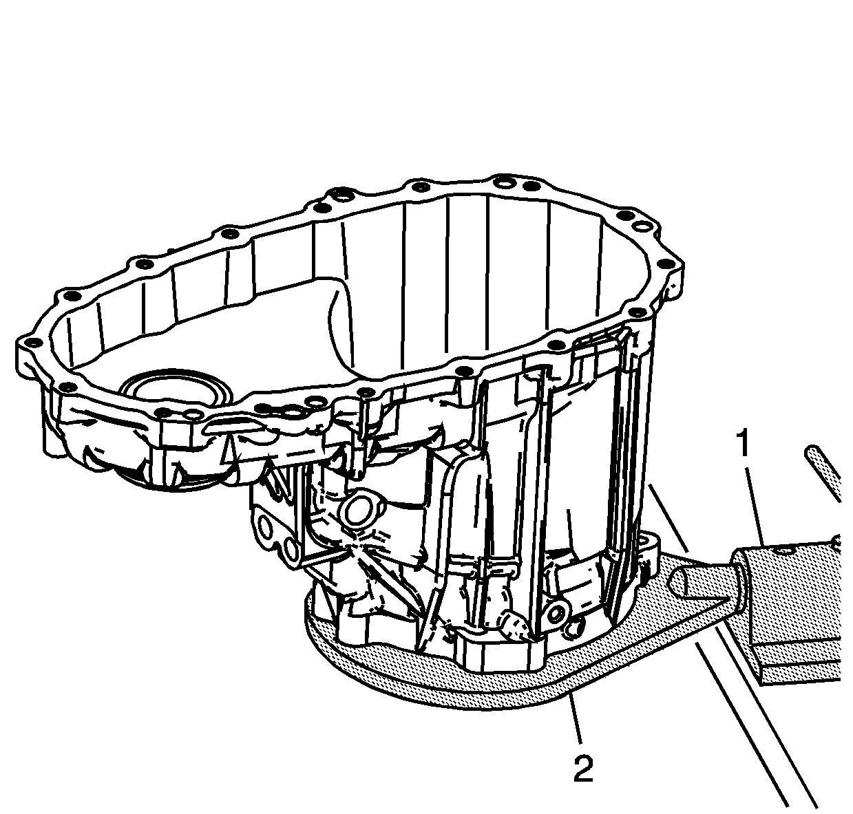
- Mount the front case half to the
J 45759 fixture
with 4 bolts.
- Install the
J 45759 fixture
(2) into the
J 3289-20 fixture
(1).
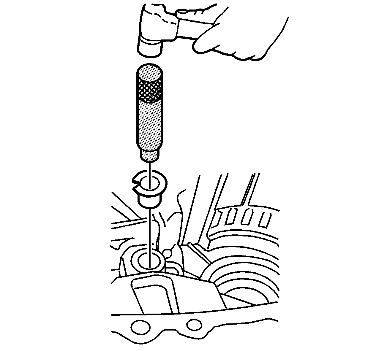
- If removed, using the
J 45936 bushing installer
, install the control actuator shaft bushing.
Caution: Refer to Fastener Caution in the Preface section.
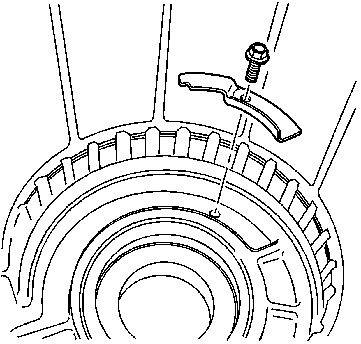
- If removed, install the breather baffle and bolt. Tighten the breather baffle bolt to
6.5 N·m (58 lb in).
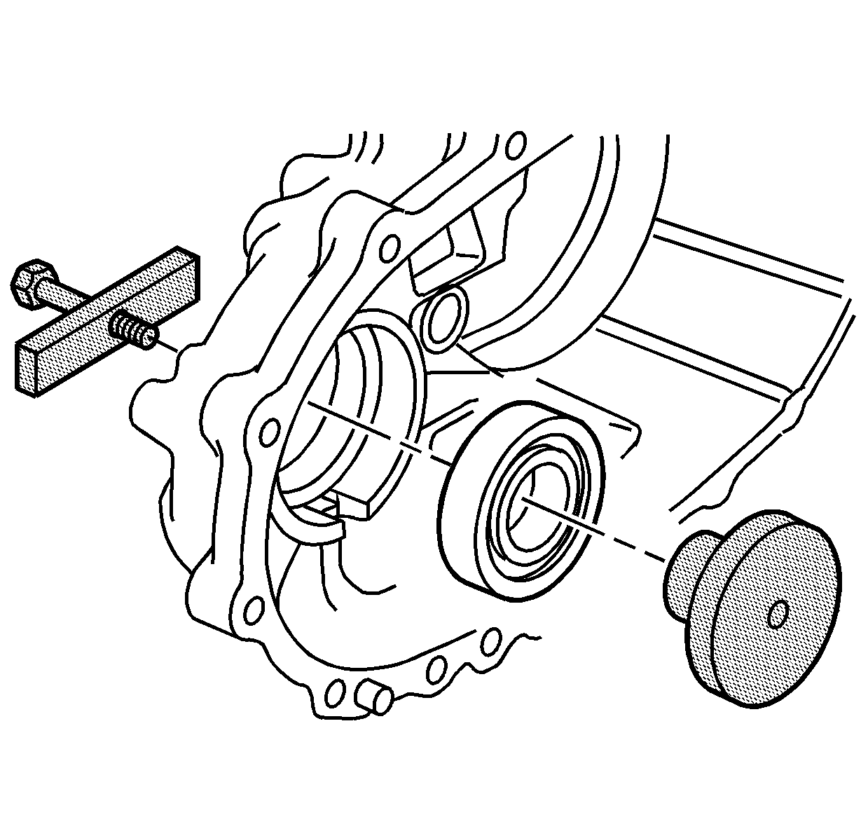
- Using the
J 36371 bearing installer
, install a new front output shaft front bearing in the front case half.
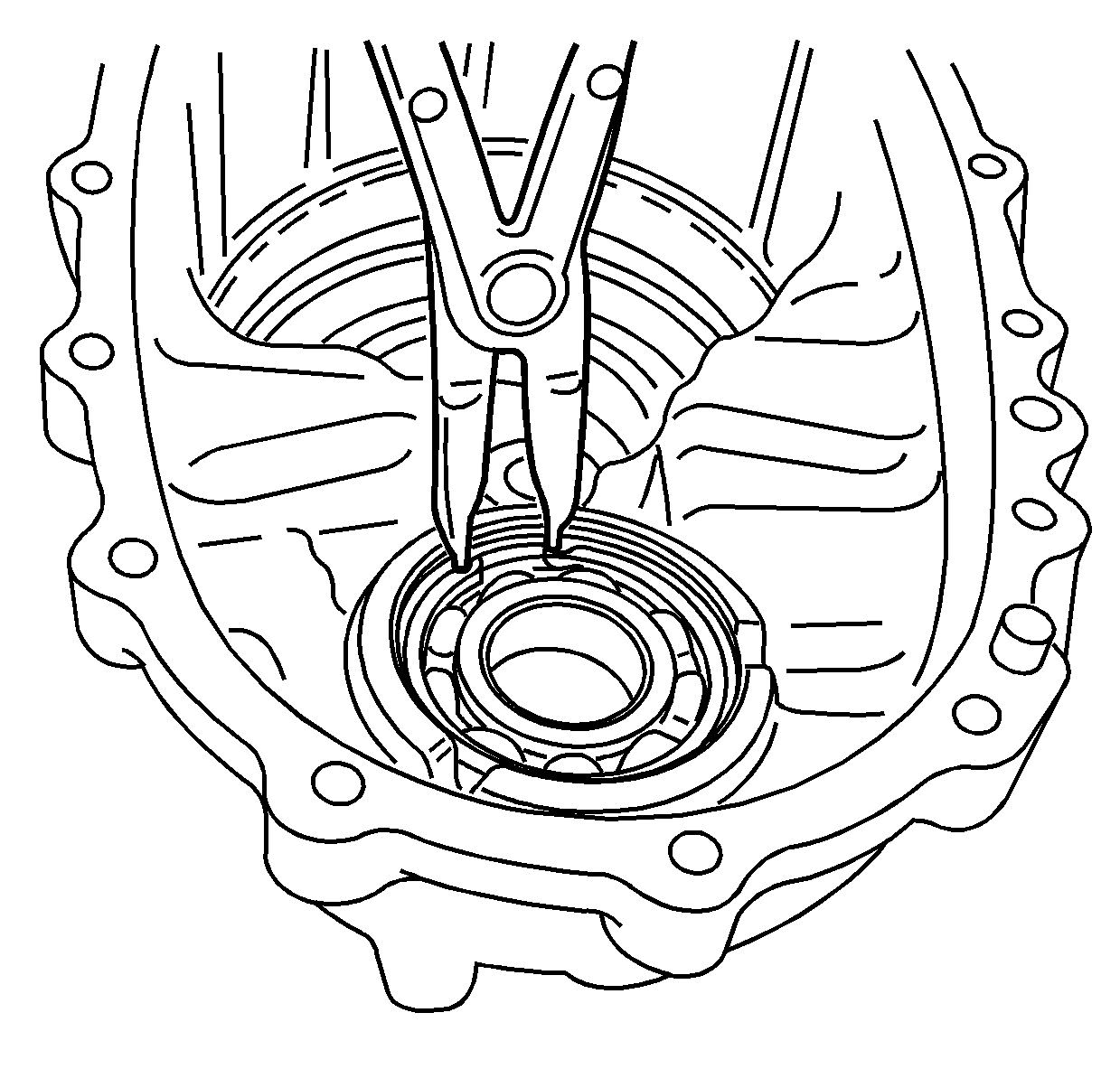
- Install a new retaining ring for the
front output shaft front bearing.
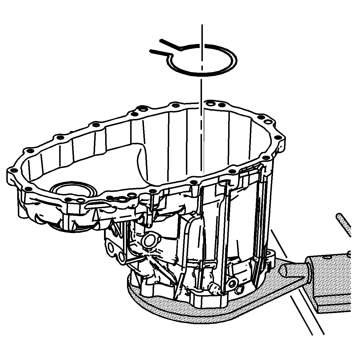
- Install the carrier bearing outer retaining ring in
the front case half.
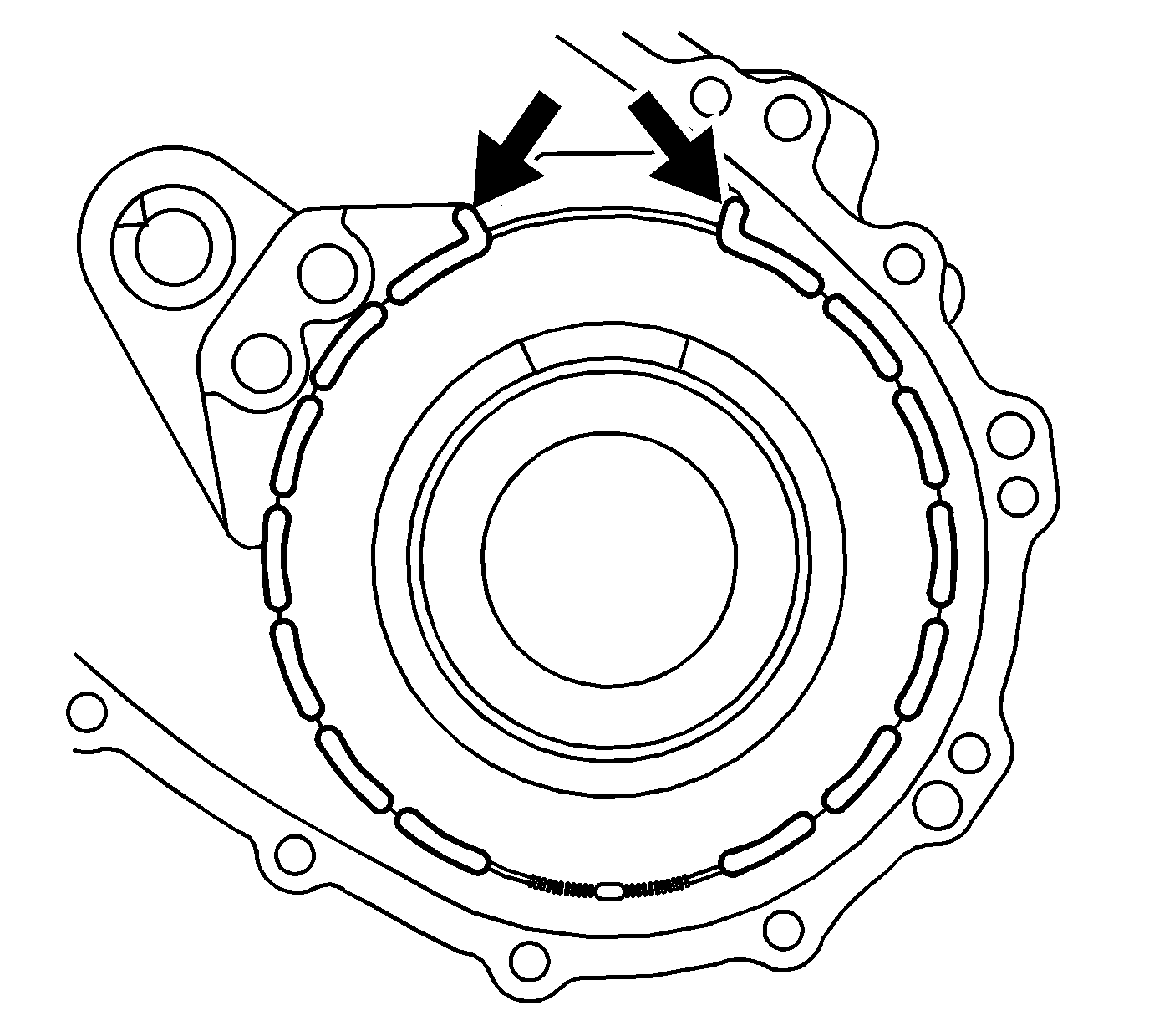
- Lubricate the annulus gear dampener with transfer case fluid.
- Install the dampener in the case.
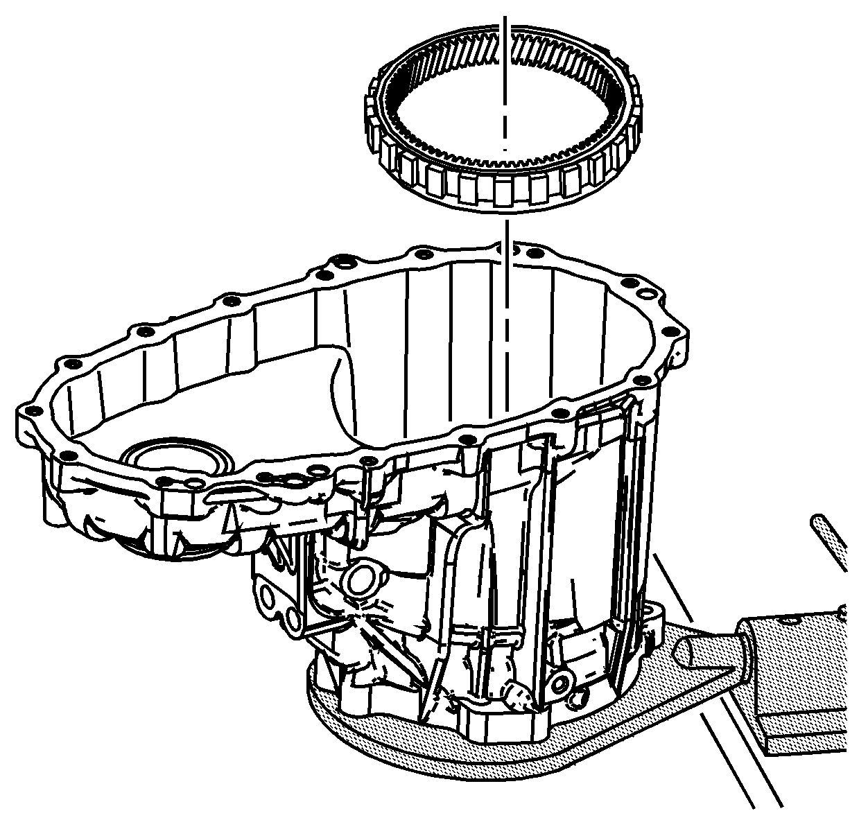
- Install the annulus gear in the front case. Ensure the dampener is still in the
correct position.
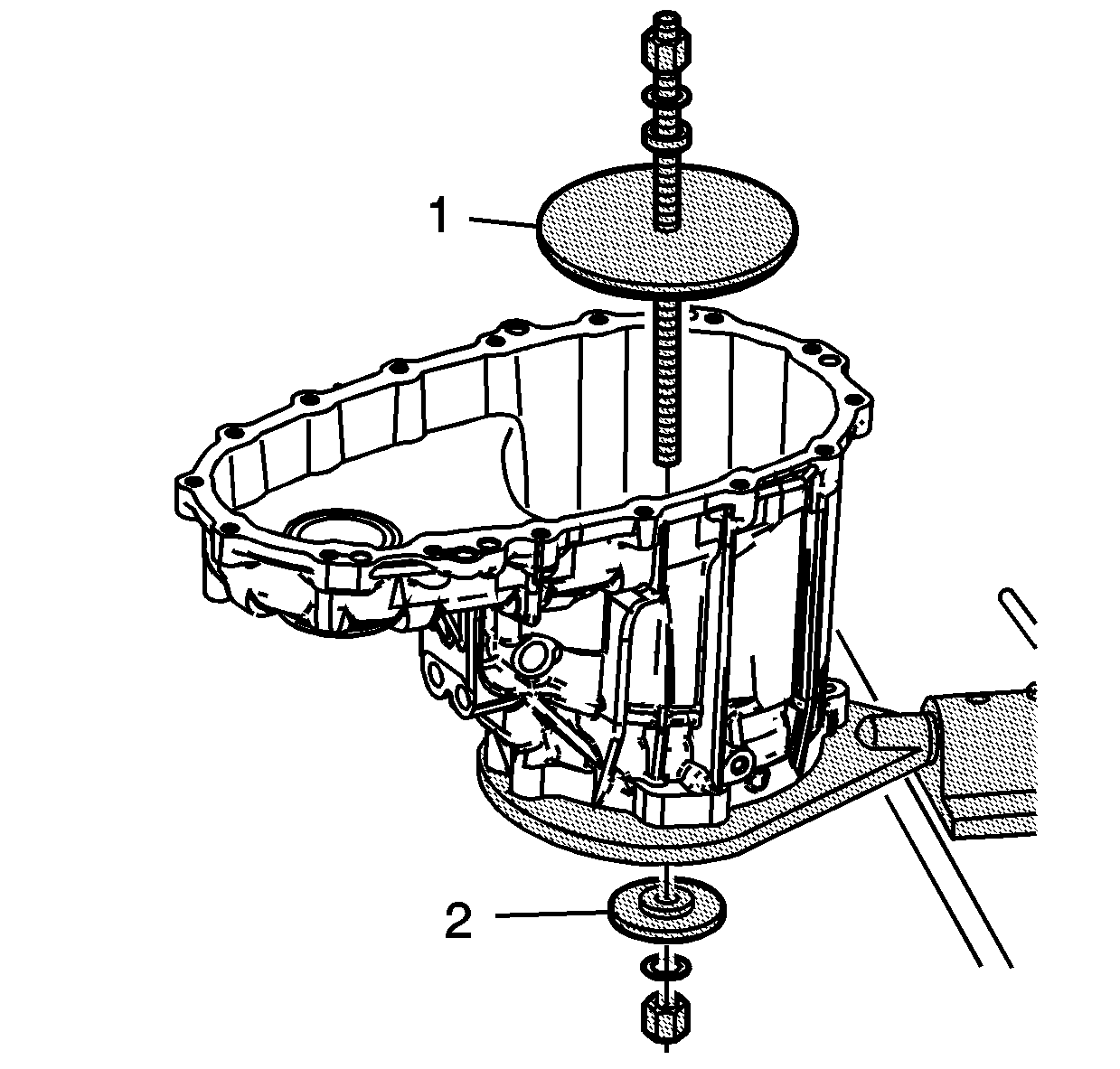
- Using the J 45933-2 (1)
and the J 45933-3 (2) of the
J 45933 assembly/disassembly kit
, compress the dampener under the annulus gear.
| • | Use the J 45933-2 (1) with the step in the annulus gear. |
| • | Use the J 45933-3 (2) in the bore of the input seal. |
| • | Compress the dampener until the groove for the annulus retaining ring is exposed. |
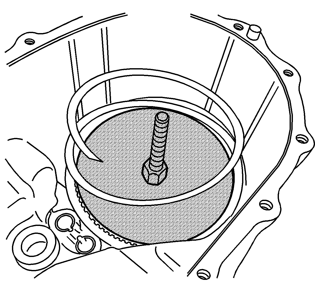
- Install the spiral retaining ring for the annulus gear.
- Remove the
J 45933 assembly/disassembly kit
and ensure the spiral retaining ring is fully seated.
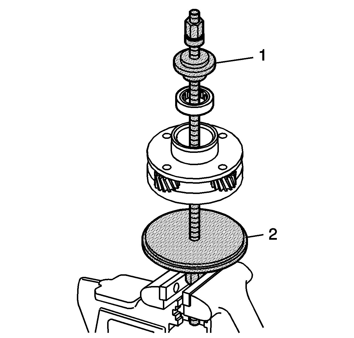
- Using the J 45933-1 (1)
and the J 45933-2 (2) of the
J 45933 assembly/disassembly kit
, install the input shaft bearing in the planetary carrier.
| • | For ease of installing the bearing, use a vise to hold the nut and the threaded shaft. |
| • | Stack the J 45933-2 and the planetary carrier over the threaded shaft. |
| • | In order to install the input shaft bearing at the proper depth, use the side of the J 45933-1 with the step against the bearing. |
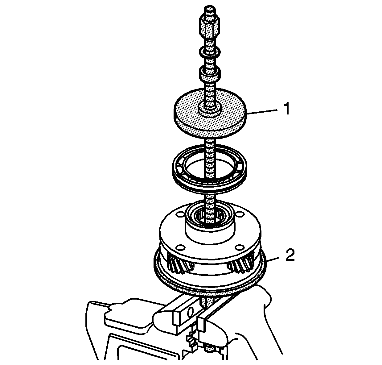
- Using the J 45933-3 (1) and the J 45933-2 (2)
of the
J 45933 assembly/disassembly kit
, install the bearing on the planetary carrier.
| • | The retaining ring groove on the bearing goes toward the planetary carrier. |
| • | For ease of installing the bearing, use a vise to hold the nut and the threaded shaft. |
| • | Stack the J 45933-2 and the planetary carrier over the threaded shaft. |
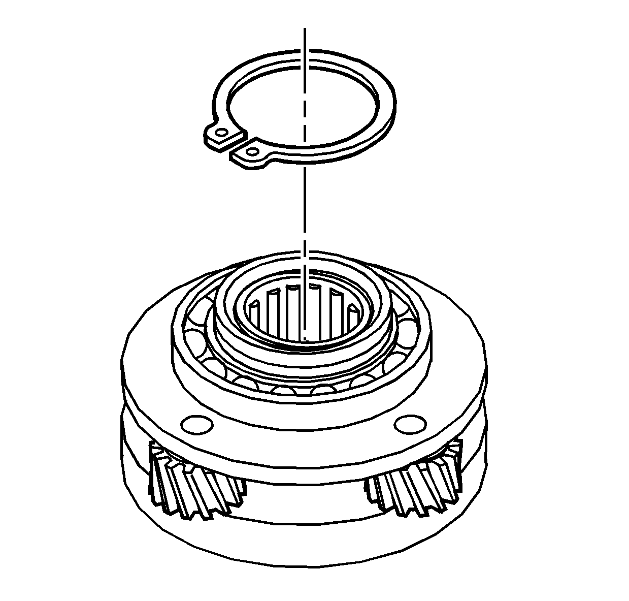
- Install the planetary carrier bearing
retaining ring.
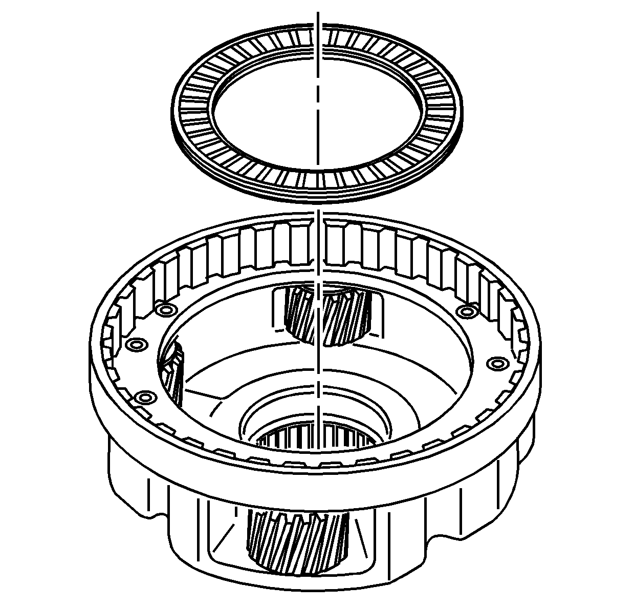
- Install the input shaft thrust bearing.
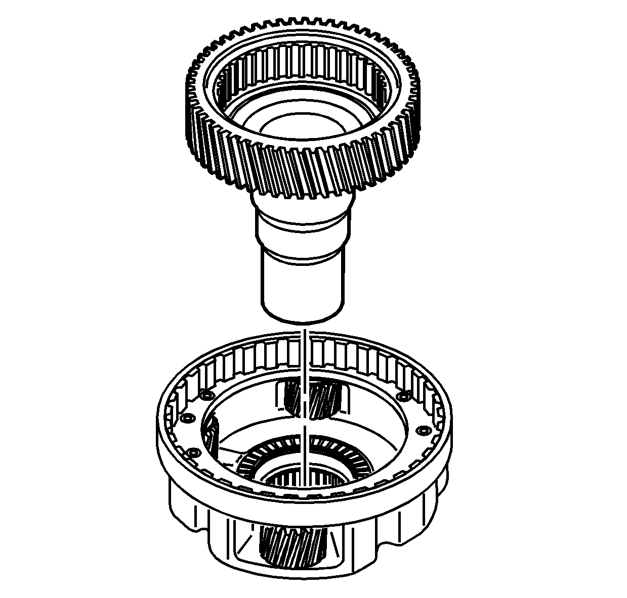
- Install the input shaft in the planetary carrier assembly.
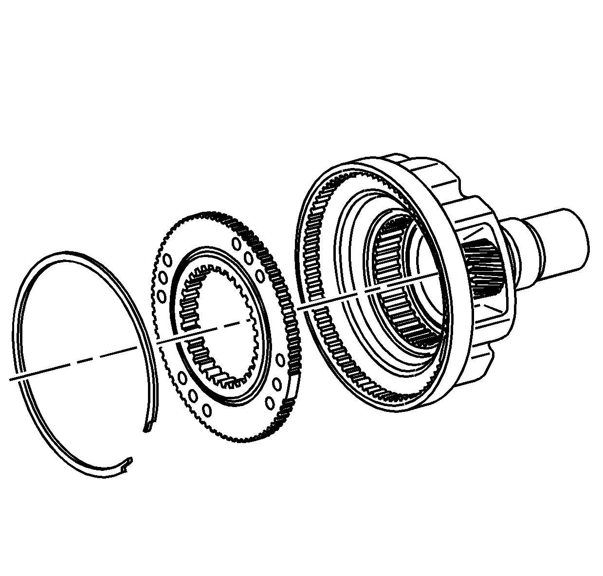
- If using the planetary carrier and
planetary carrier low gear again, align the marks from disassembly.
- Install the planetary carrier low gear. The side with the thrust surface faces toward the input shaft.
- Install the planetary carrier low gear retaining ring.
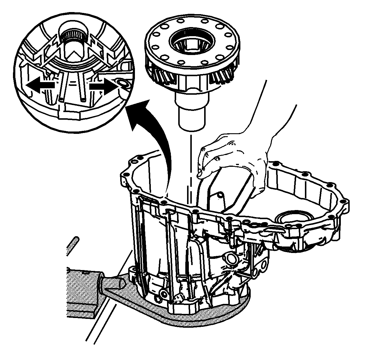
Note: Ensure the snap ring pliers do not catch on the ribs of the case. The retaining ring must be fully opened and retracted in the groove.
- Using a large pair of snap ring pliers, spread the carrier bearing retaining ring.
- While the retaining ring is spread, install the planetary carrier assembly.
- Ensure the retaining ring is secured on the planetary carrier bearing.
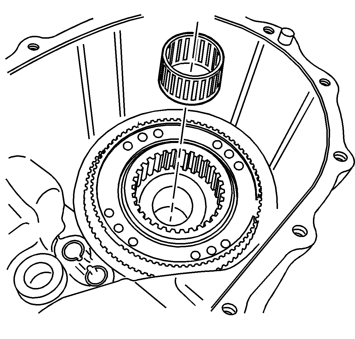
- Install the rear output shaft front support bearing.
- Using
J 36850 lubricant
, pack the bearing.
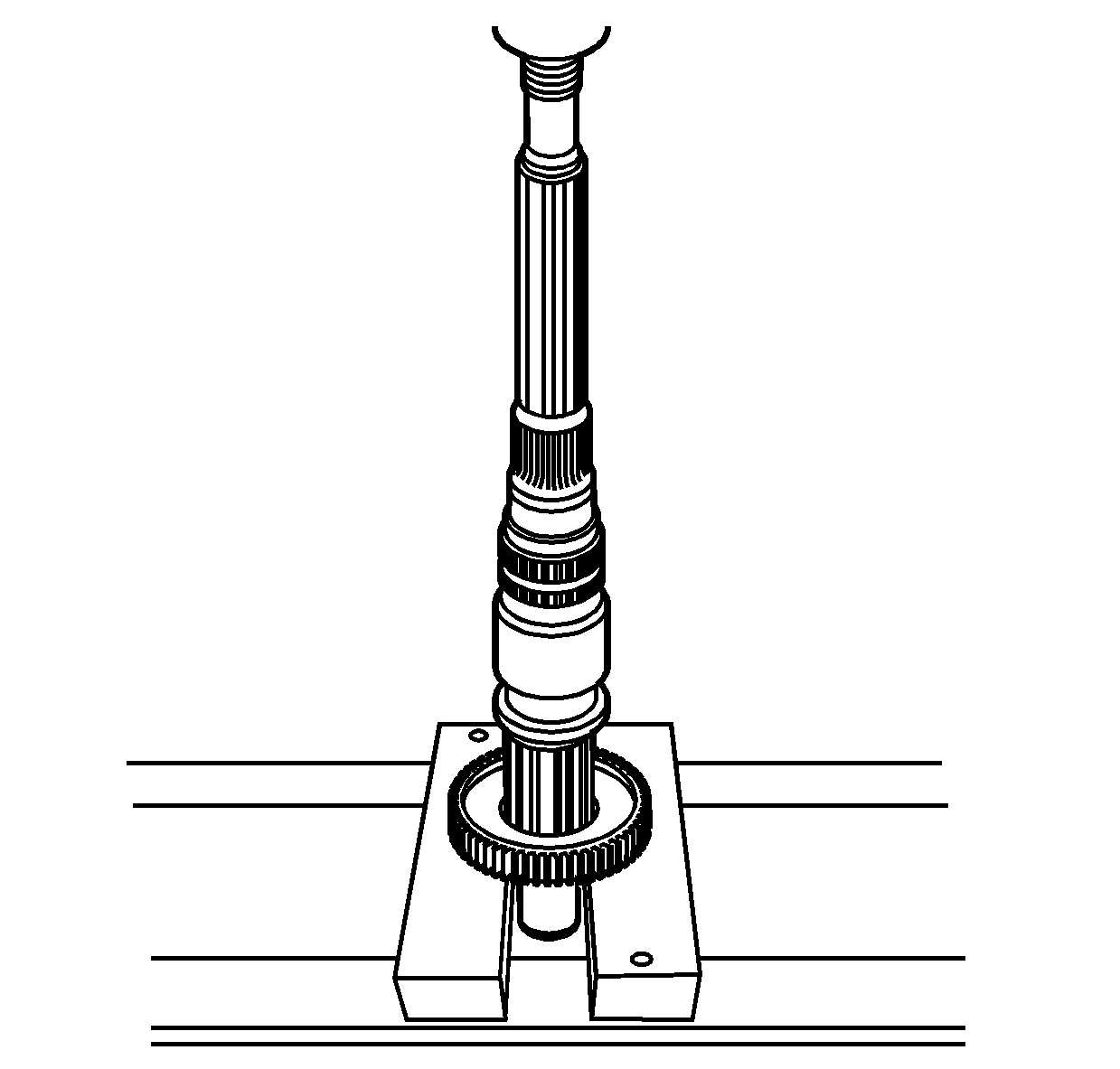
- Using a hydraulic press, install the 2/4 synchronizer hub.
| • | The non-shoulder side of the hub aligns to the rear of the rear output shaft. |
| • | Ensure the hub is supported on the shoulder flange, not on the external hub teeth. |
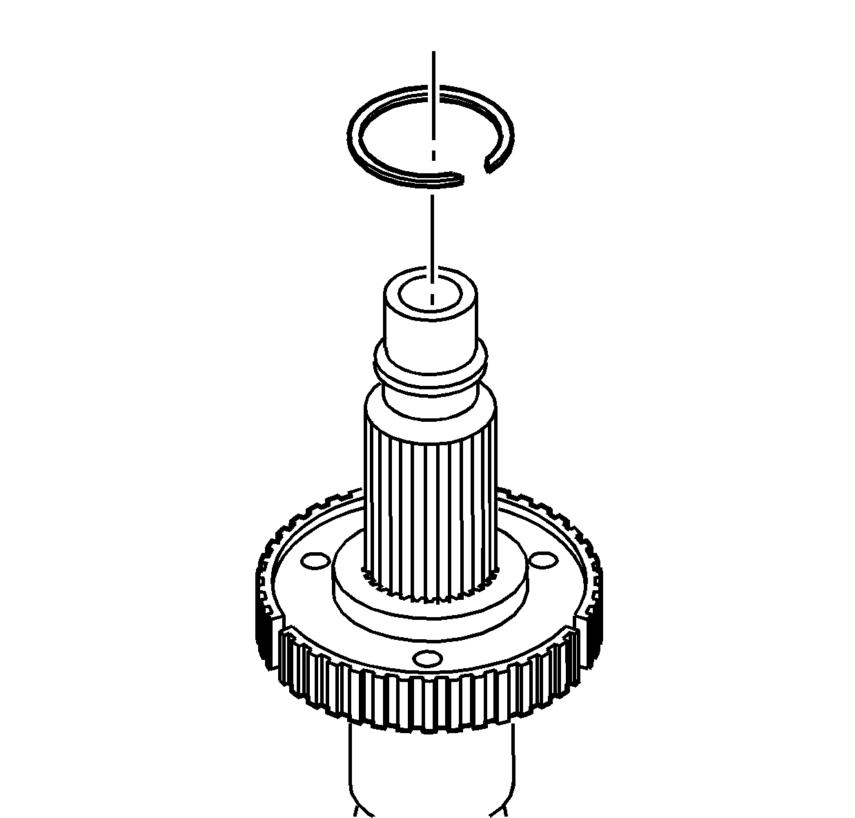
- Install the synchronizer hub retaining
ring.
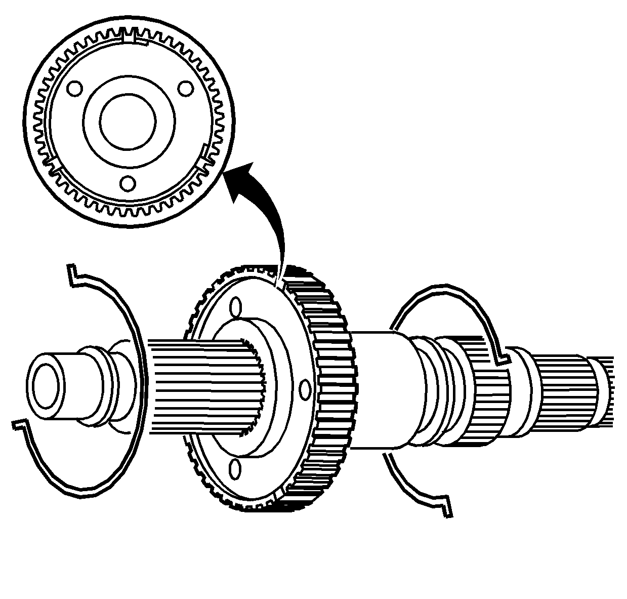
- Install the rear spring on the synchronizer hub.
- Align the spring ends by the insert slots.
- Install the front spring, with the ends opposite from the rear spring, on the synchronizer hub.
- Align the spring ends by the insert slots.
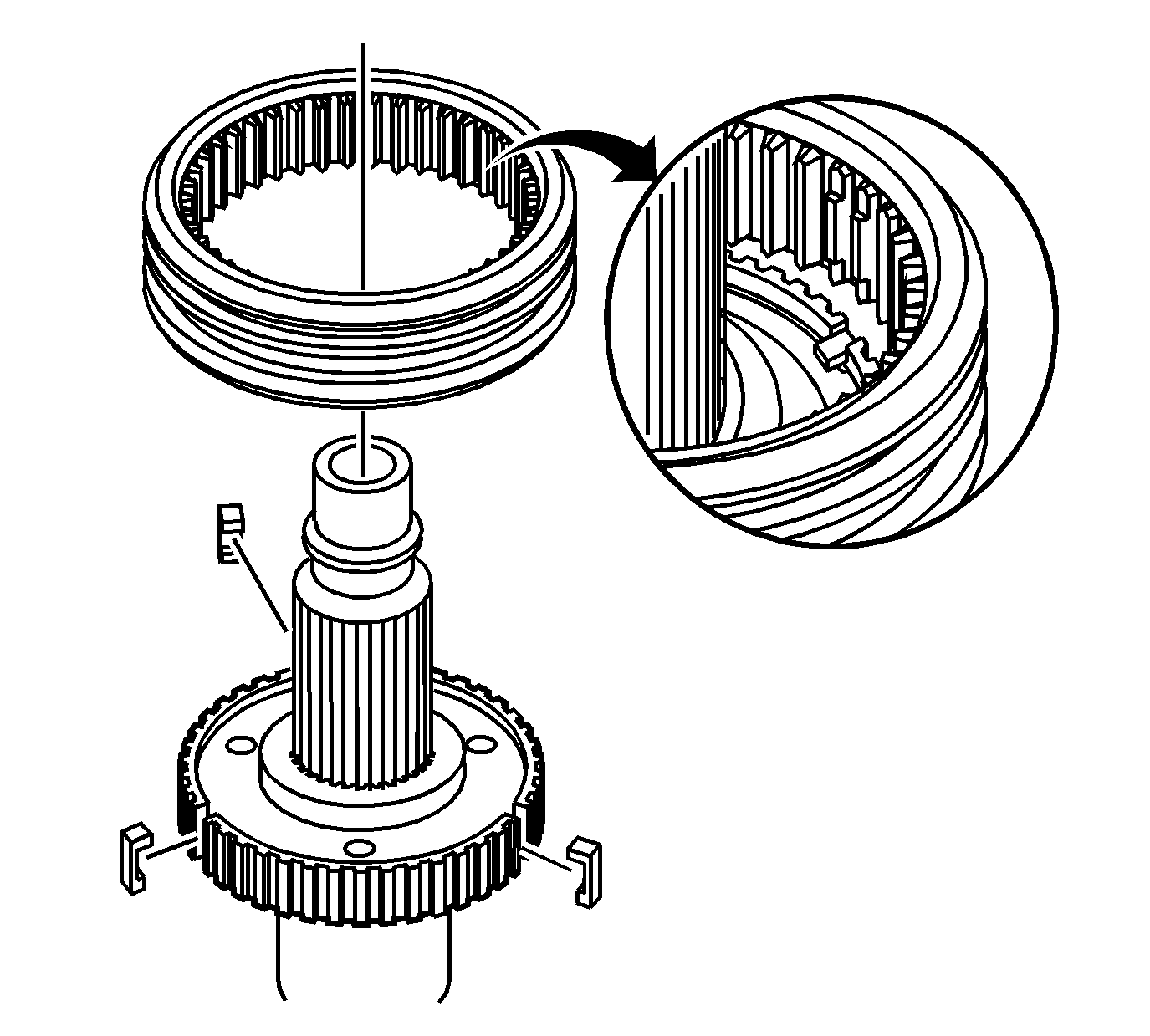
- Install the three synchronizer inserts in the synchronizer hub.
- Install the synchronizer sleeve.
| • | The sleeve shoulder with the groove aligns forward. |
| • | Align the flat teeth of the sleeve with the insert. |
| • | Push in on the inserts. |
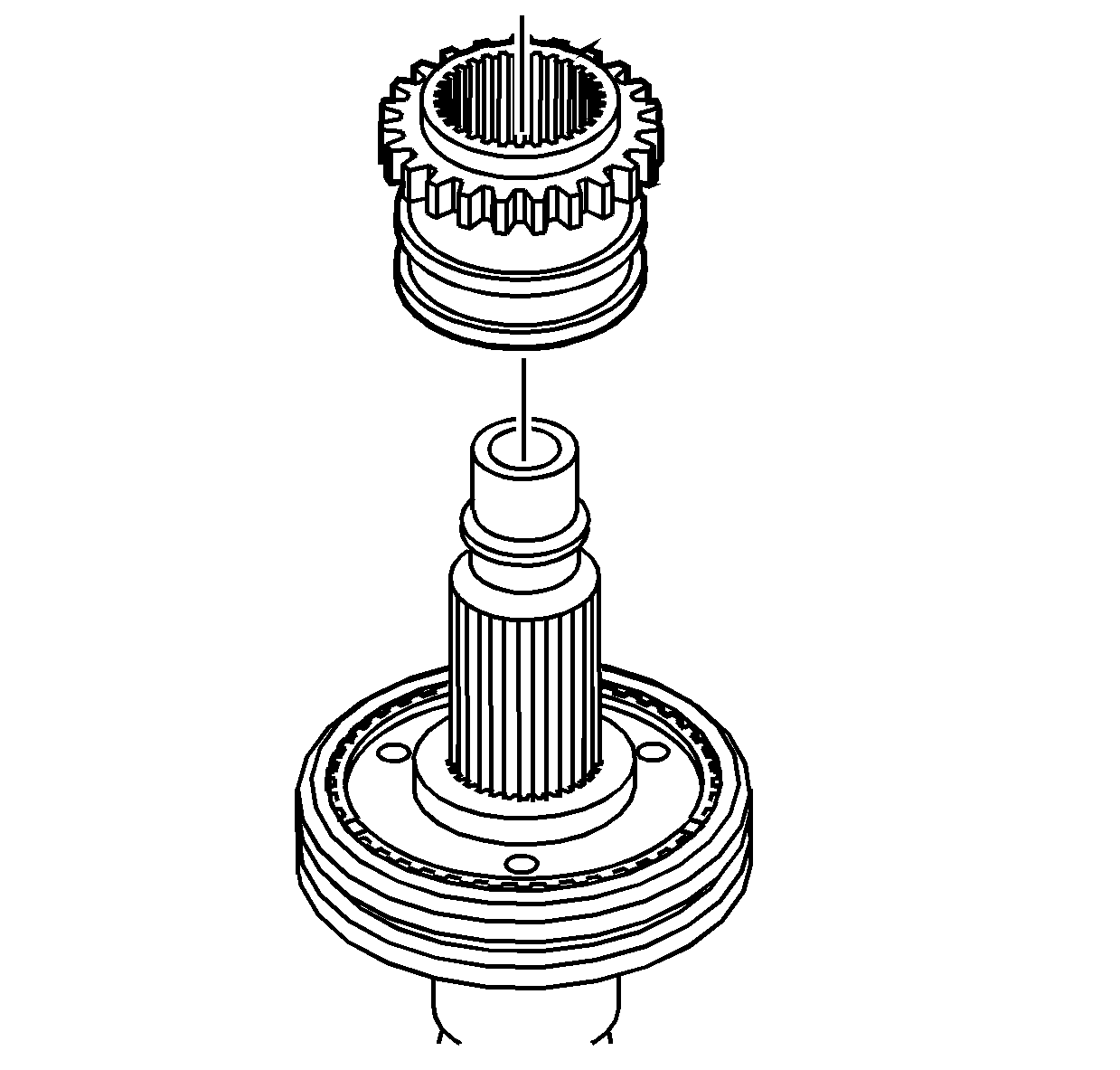
- Install the high/low range sleeve.
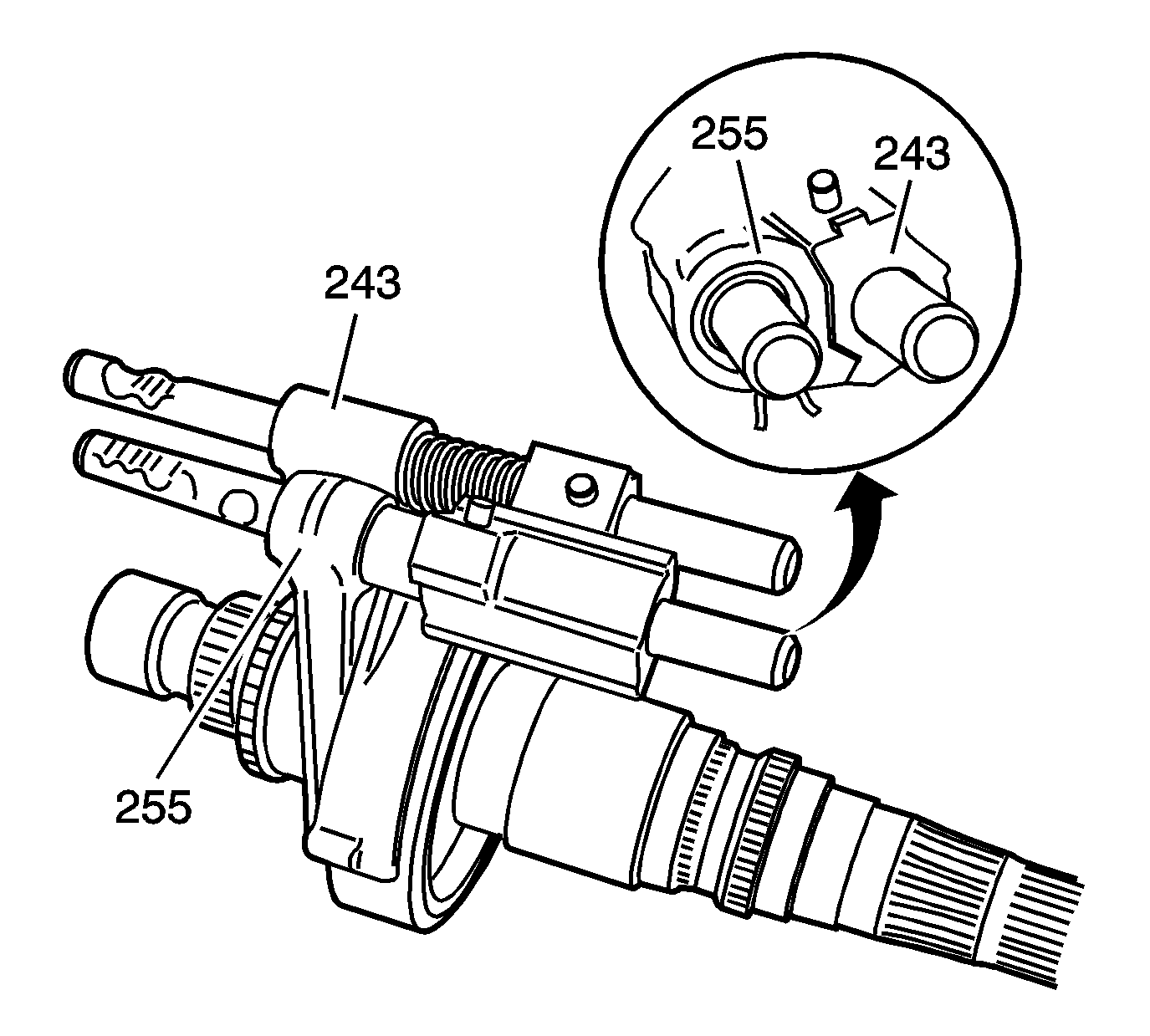
- Install the high/low shift fork assembly (255)
to the high/low range sleeve.
- Install the 2/4 shift fork assembly (243) to the 2/4 synchronizer sleeve.
- Align the shift blocks as shown.
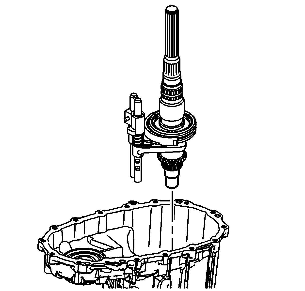
- Lubricate the shift shaft holes in
the front case with transfer case fluid.
- Install the rear output shaft, with the shift forks, to the front case half.
| • | Hold the shift forks in position to the sleeves. |
| • | Install the shift shafts in the holes in the case. |
| • | Align the high/low range sleeve teeth with the planetary low gear teeth. |
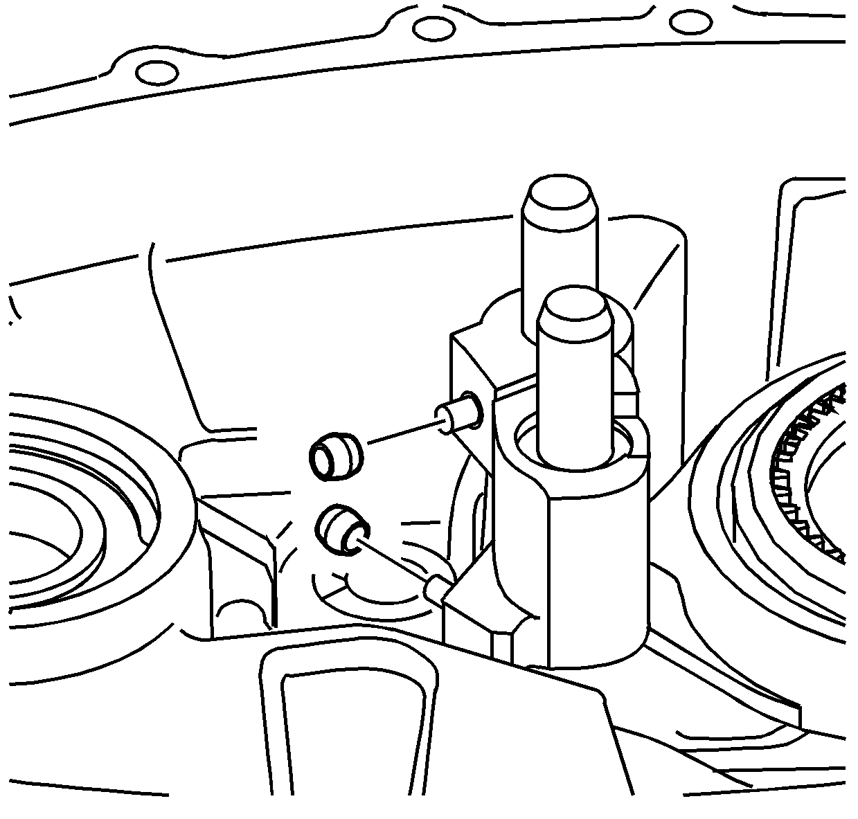
- Install the rollers on the shift forks.
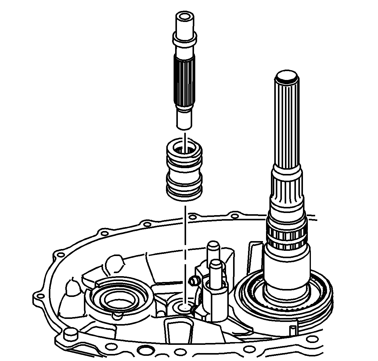
- Install the control actuator cam. The smaller recess
on the cam goes up and faces toward the shift rails.
- Rotate the control actuator cam to align to the shift forks.
- Install the control actuator shaft. Align the large spline on the shaft with the large groove in the cam.
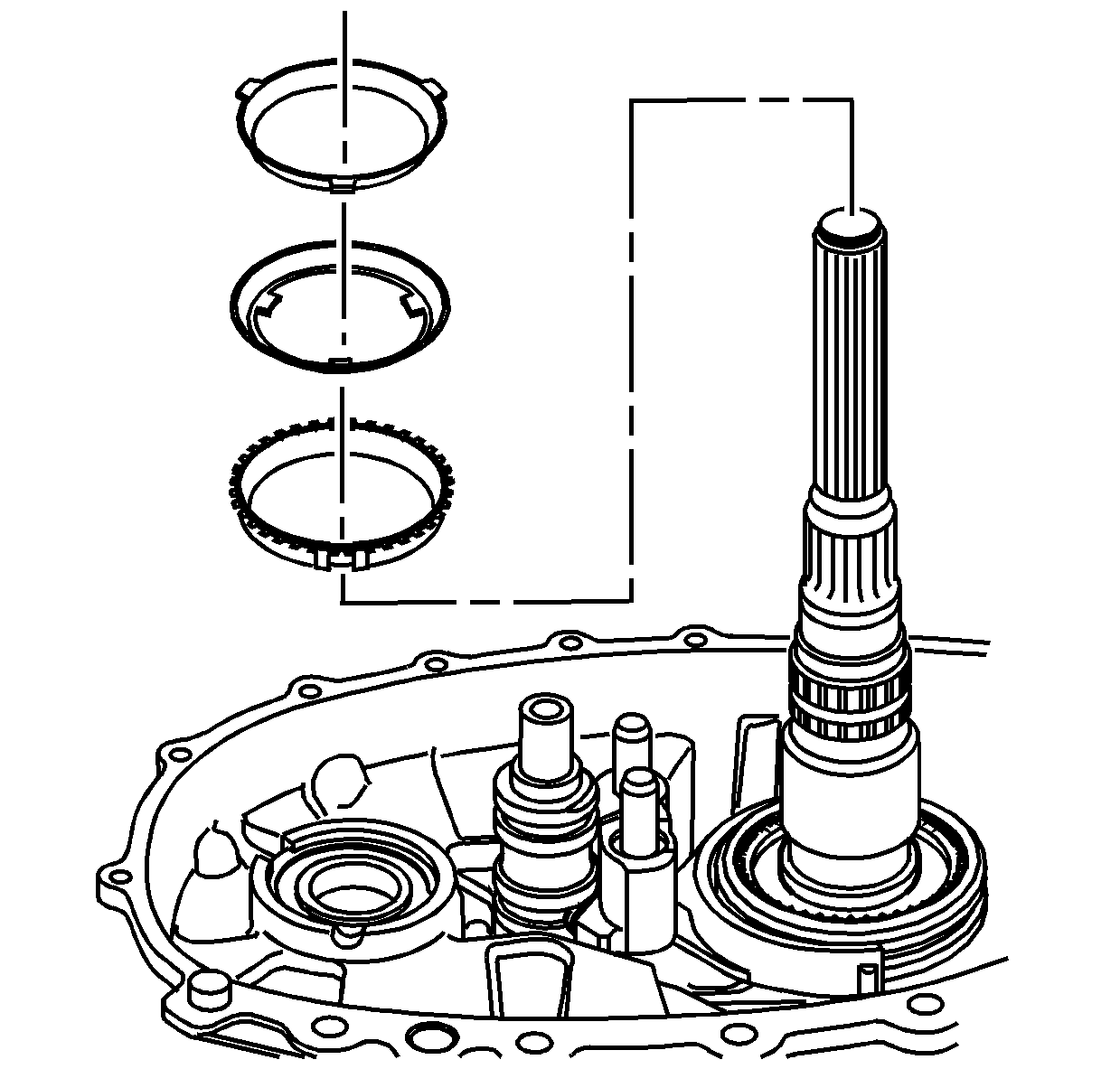
- Install the 2/4 synchronizer blocking ring. Align the tabs on the ring with the
insert grooves on the synchronizer hub.
- Install the 2/4 synchronizer middle ring.
- Install the 2/4 synchronizer inner ring.
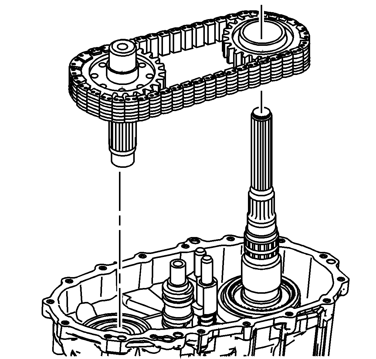
- Lubricate the journal on the rear output
shaft, for the drive sprocket, with transfer case fluid.
- With the blue link pointing to the rear case, install the chain on the drive sprocket and the driven sprocket.
- Install the chain, the front output shaft and the drive gear.
- Rotate the drive gear to align with the tabs on the 2/4 synchronizer rings.
- Inspect to ensure the drive gear and the rear output shaft assembly are installed properly. View the chain from the side. The chain links will be parallel to the case sealing flange. If the chain links are not parallel to the case, disassemble until
the condition is found.
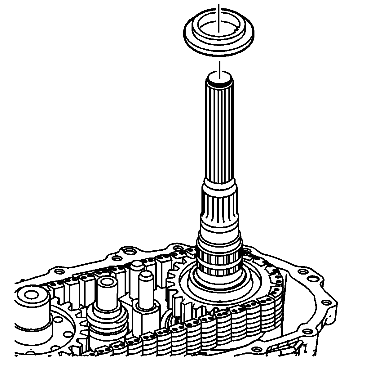
- Install the drive gear thrust washer. Align the thrust washer teeth with the flat
area on the rear output shaft.
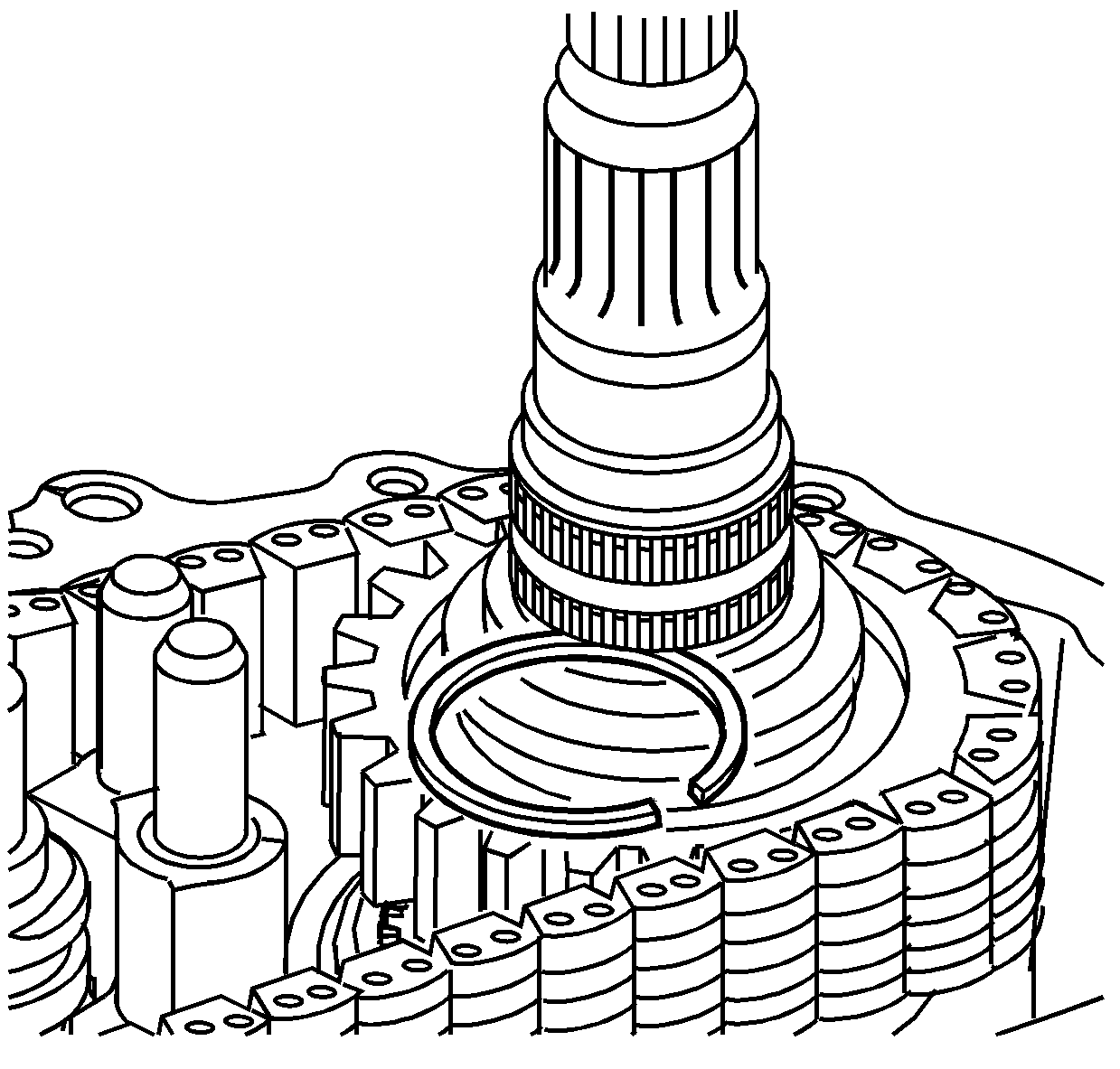
Note: The drive sprocket retaining rings are select fit. Use only a new retaining ring.
- Select the thickest drive sprocket retaining ring that will fit in the groove. Four sizes are available.
- Install the drive sprocket retaining ring.
- Measure the retaining ring outside diameter. If the measured diameter is larger than the specified range, use a thinner retaining ring. Retaining ring outside diameter:
53.0 +/- 0.5 mm (1.969 +/- 0.020 in)
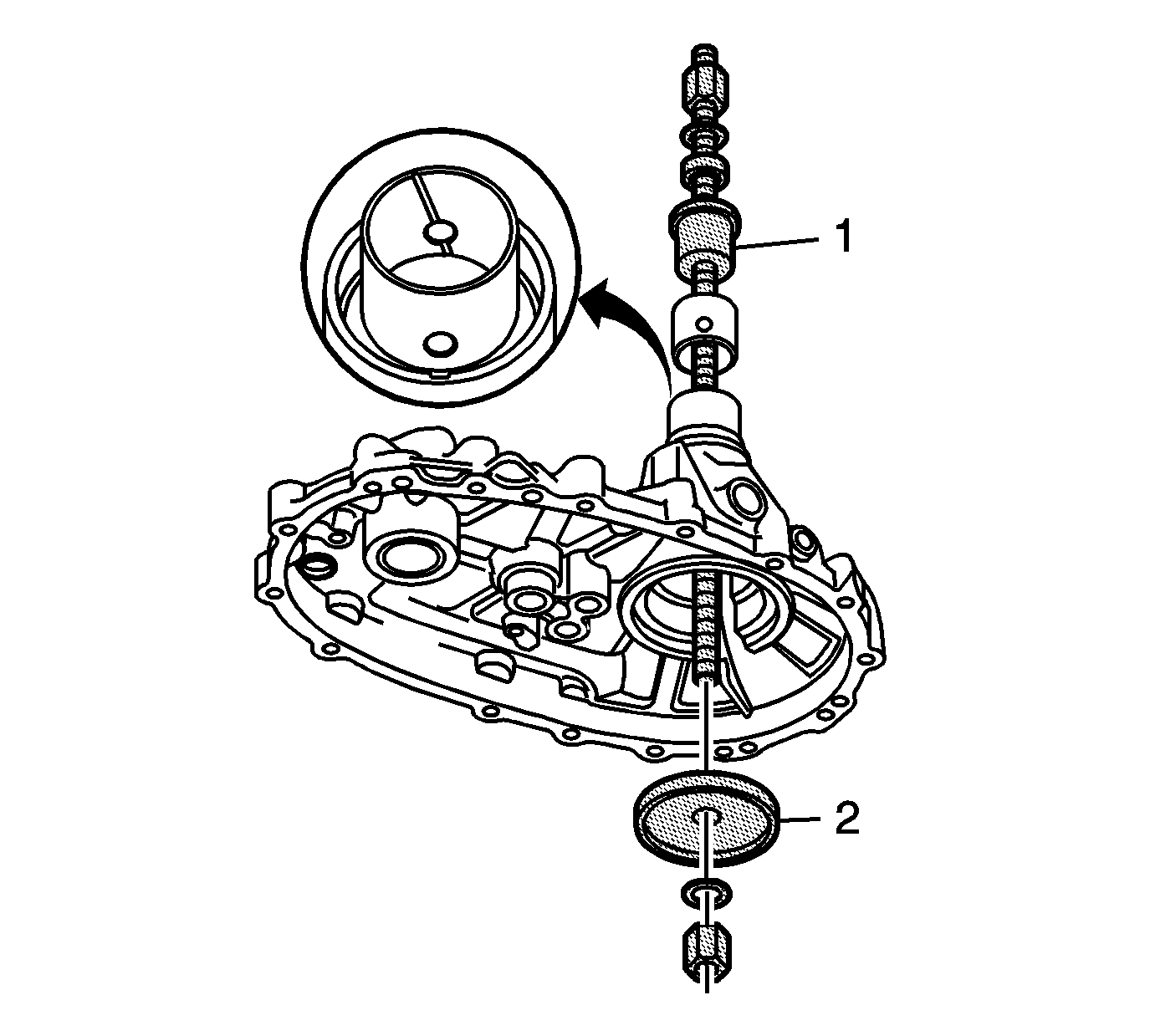
Note:
| • | Use the thrust bearing between the J 45933-4 (1) and a washer. |
| • | Ensure the threads of the threaded shaft on the
J 45933 assembly/disassembly kit
are lubricated with the supplied lubricant. |
- If removed, install the rear bushing in the rear case, using the J 45933-4 (1) and the J 45933-3 (2) of the
J 45933 assembly/disassembly kit
.
| • | Align the holes of the bushing with the oil grooves in the case. |
| • | The bushing installed depth is just past the shoulder in the case. |
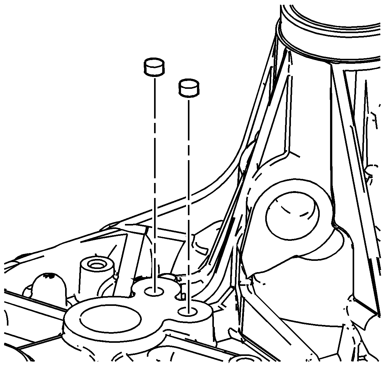
- If necessary, install the shift shaft plugs. Use threadlocker
GM P/N 12345382 (Canadian P/N 10953489), or equivalent, on the plugs.
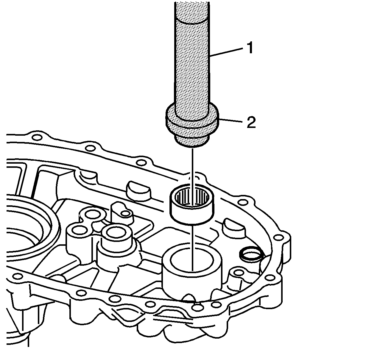
- Using
J 8092 driver
(1) and
J 46199 bearing remover/installer
(2), install the front output shaft rear bearing. The part numbers on the bearing align
away from the case and toward the tool.
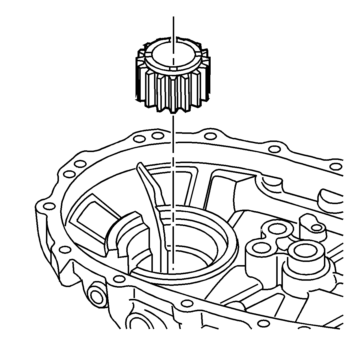
- Position the speed sensor reluctor wheel in the rear case half, with the oil grooved
side toward the inside of the rear case half.
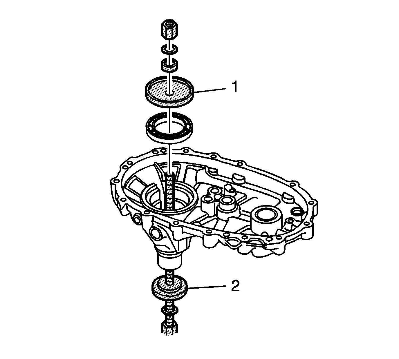
- Install the rear output shaft bearing in the rear case
half, using the J 45933-3 (1) and the J 45933-1 (2) of the
J 45933 assembly/disassembly kit
.
| • | Use the single shoulder side of the J 45933-3 in the rear seal bore. |
| • | Ensure the bearing is being installed square to the bearing bore. |
| • | Install the bearing until it bottoms in the bearing bore. |
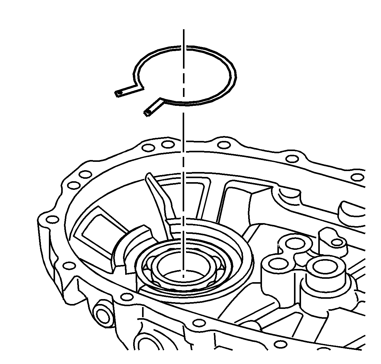
- Install the rear output shaft bearing
retaining ring.
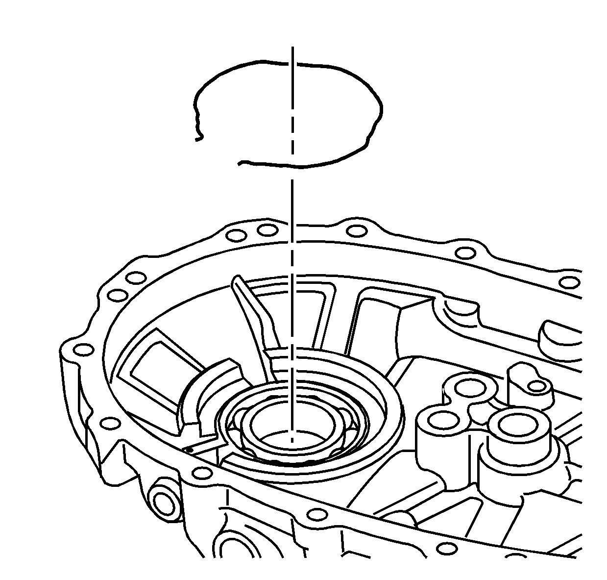
- Install the oil pump wire retaining ring, with the ends aligning in the larger
open area of the bore.
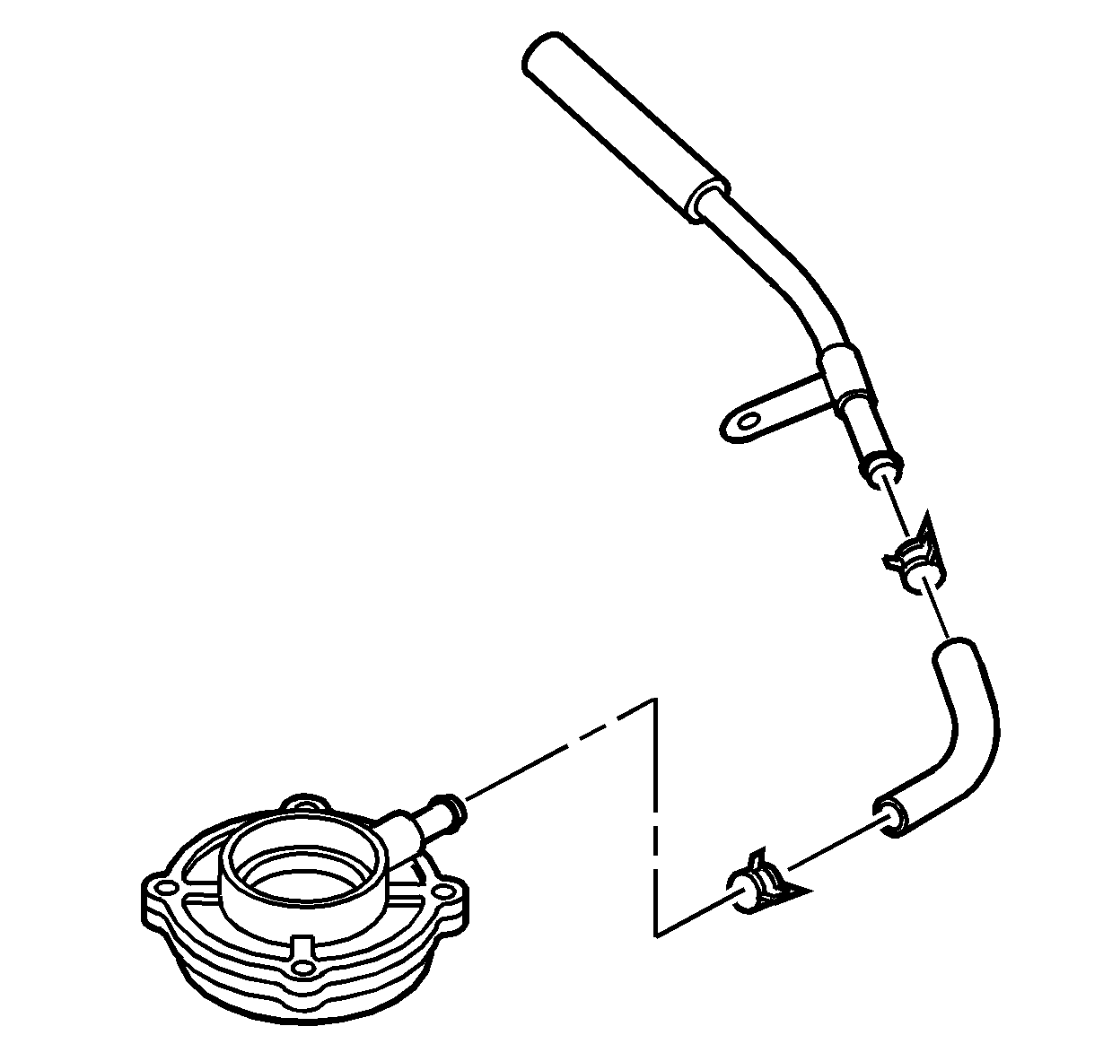
- Prelube the oil pump.
| 76.1. | Pour a small quantity of transfer case fluid in the oil suction pipe fitting. |
| 76.2. | Rotate the oil pump gear a few turns. |
- Install the oil pump suction hose to the oil pump.
- Install the oil pump suction hose to the oil pump screen.
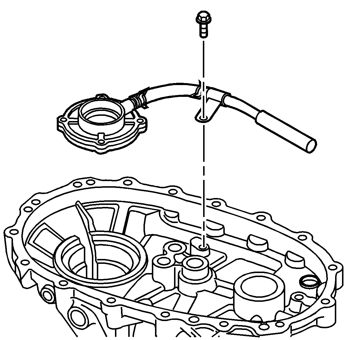
- Install the oil pump, with the screen, in the rear case
half. Push on the oil pump and it will snap into position.
- Install the oil pump suction tube bolt. Tighten the suction tube bolt to
15 N·m (11 lb ft).
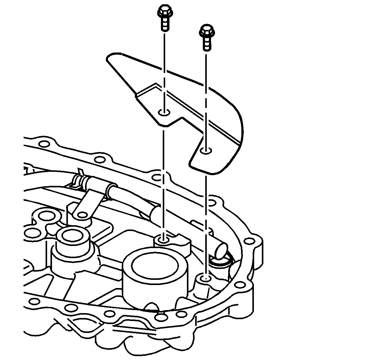
- Install the oil deflector and bolts. Tighten the deflector bolts to
15 N·m (11 lb ft).
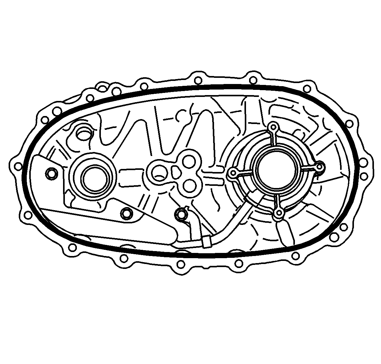
Caution: Apply the proper amount of sealant to the flange when assembling the transfer case. Excessive amounts of sealant can plug the oil pump screen, resulting in internal component failure.
Note:
| • | Ensure that the sealing surfaces of the front and rear case halves are free of dirt, oil and cleaning solvent. |
| • | Ensure the locating pins are installed in the front case half. Install the locating pins if necessary. |
- Apply a 3 mm (1/8 in) bead of flange sealant GM P/N 12378517 (Canadian P/N 88900757) to the sealing flange on the rear case half. Apply the sealer evenly to the inside surface of the bolt holes, with no gaps.
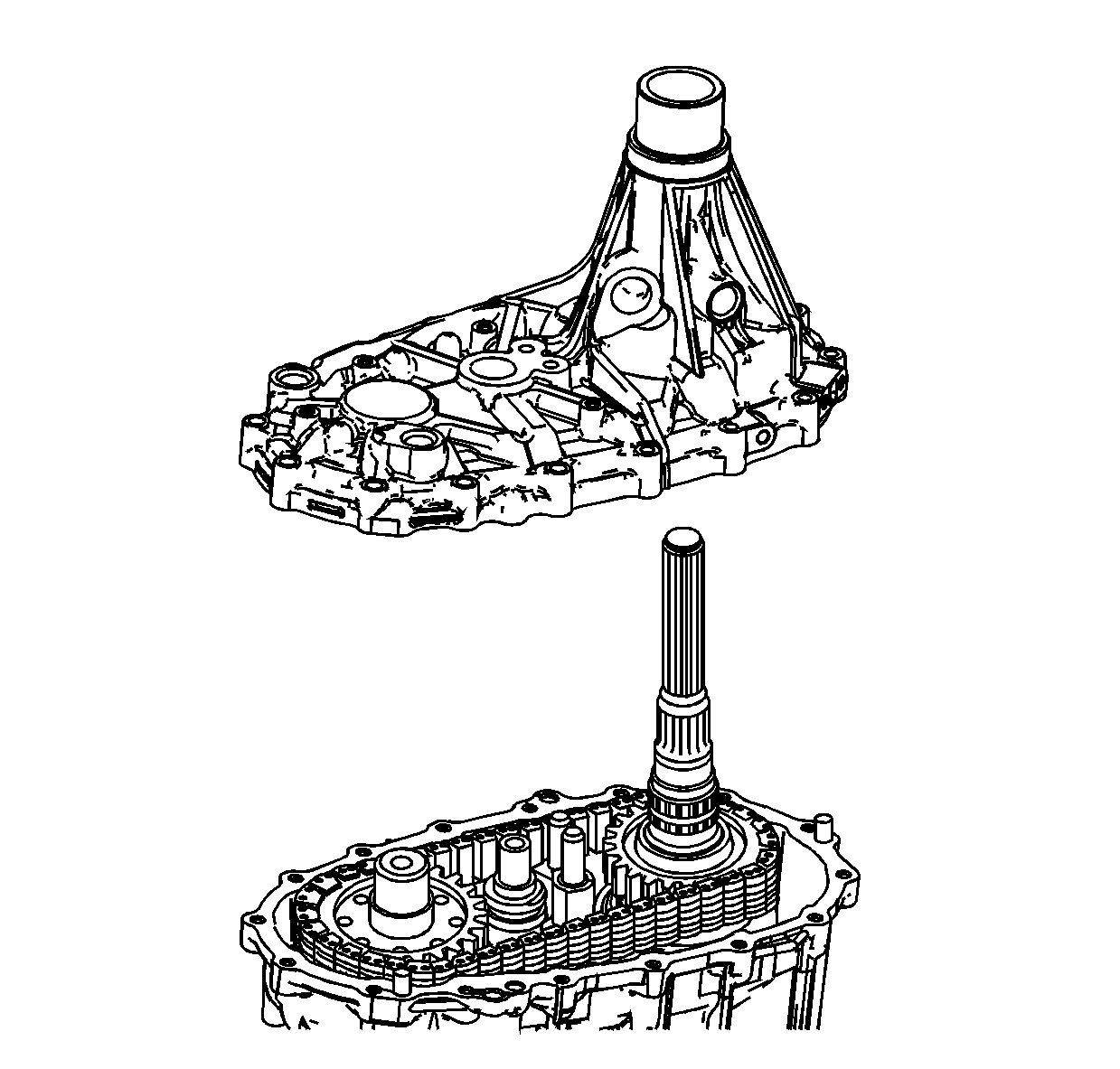
Note: The locating pins must be installed in the front case half.
- If necessary, install the locating pins in the front case half.
- Install the rear case half.
| • | Rotate the input shaft to allow the rear output shaft to align with the speed sensor reluctor wheel splines. |
| • | Lightly tap down on the rear case half to fully install on the locating pins. |
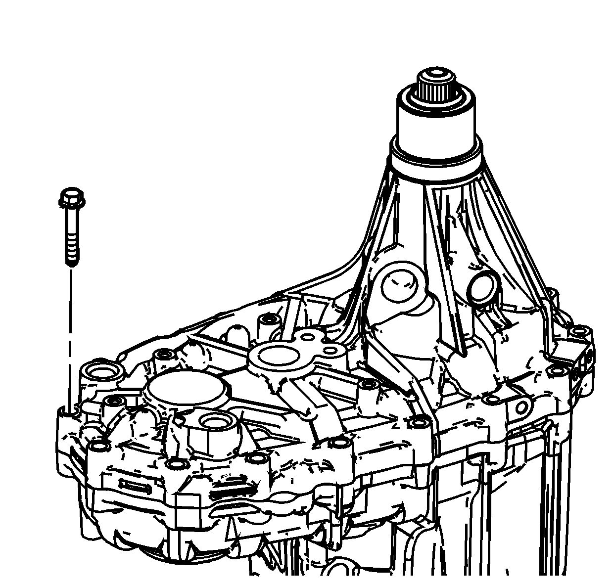
- Install the case half bolts. Tighten the case half bolts to
22 N·m
(16 lb ft).
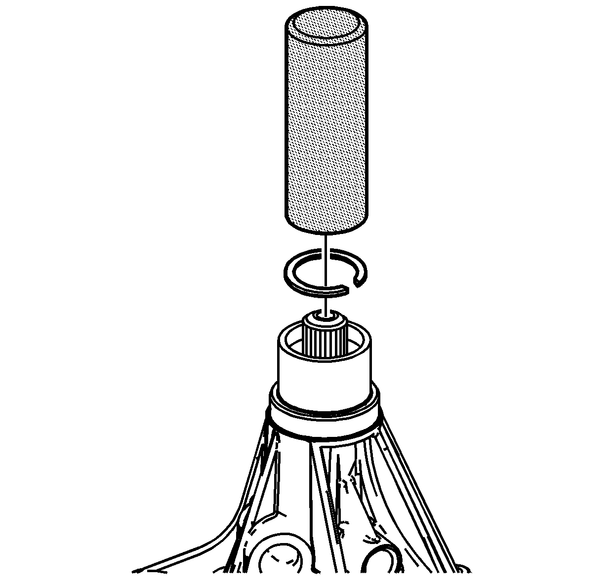
- Position a new rear output shaft retaining ring over
the rear output shaft.
Note: Push inward against the input shaft to expose the retaining ring groove and allow the retaining ring to seat fully into the groove.
- Using the
J 45937 retaining ring installer
, install the retaining ring. Tap lightly, or use hand pressure on the
J 45937 retaining
ring installer
until the retaining ring installs in the groove.
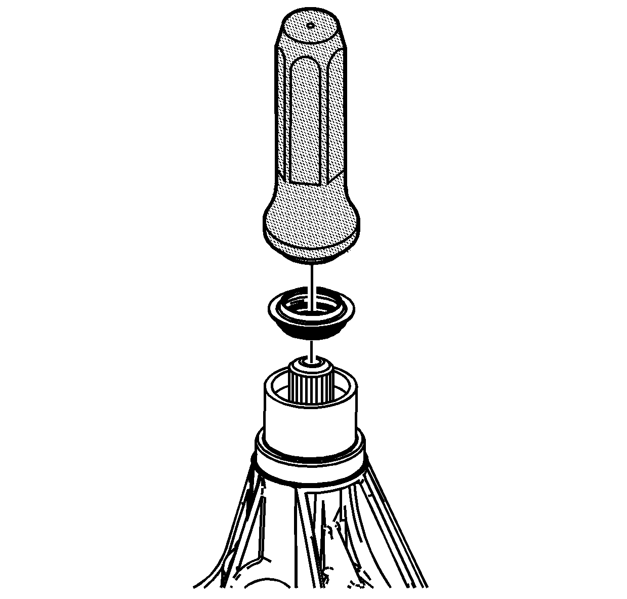
- Using the
J 35582 seal installer
with a hammer, install the rear output shaft seal.
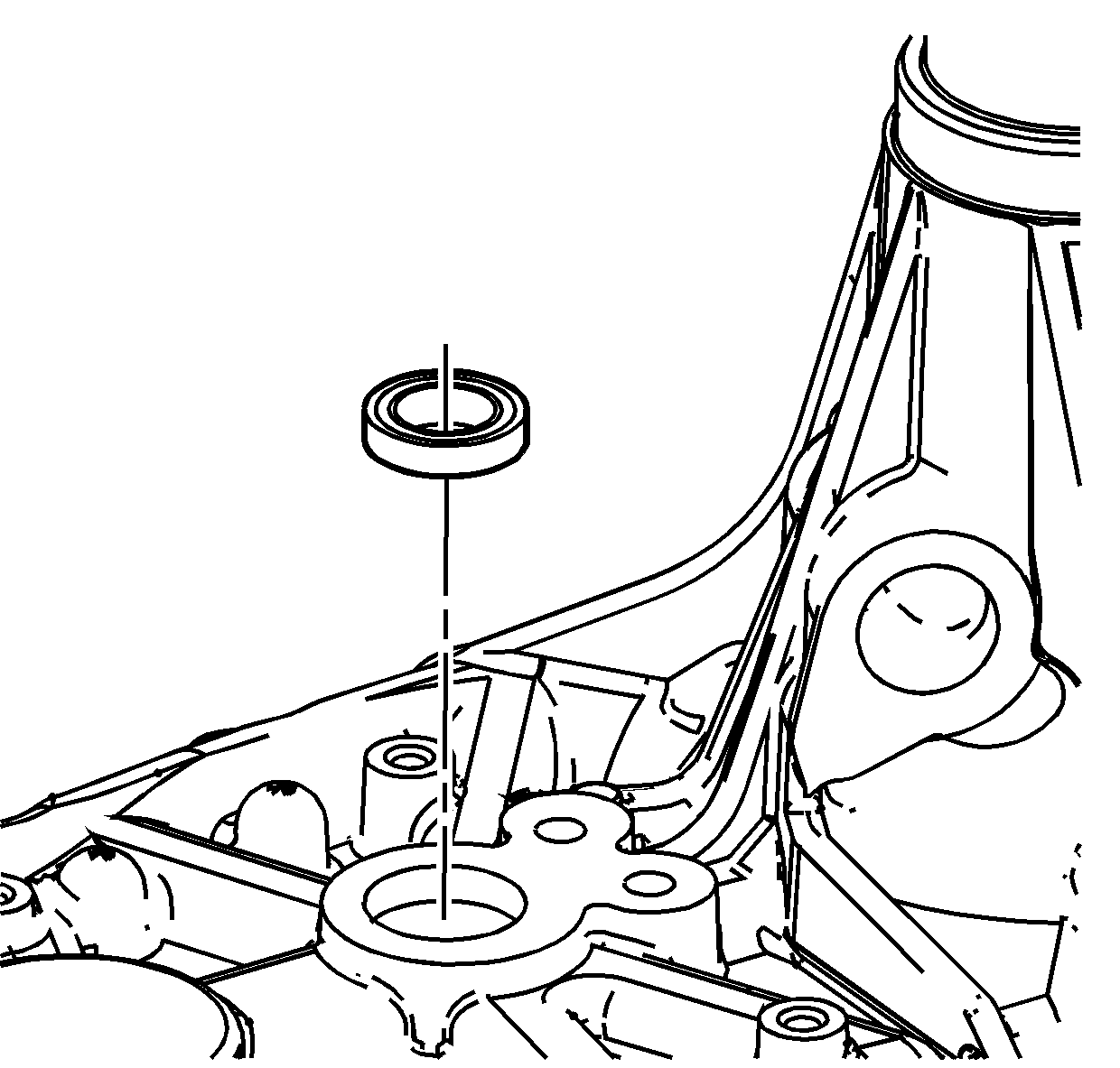
- Install the control actuator shaft seal flush to the case surface. The spring
side installs to the inside.
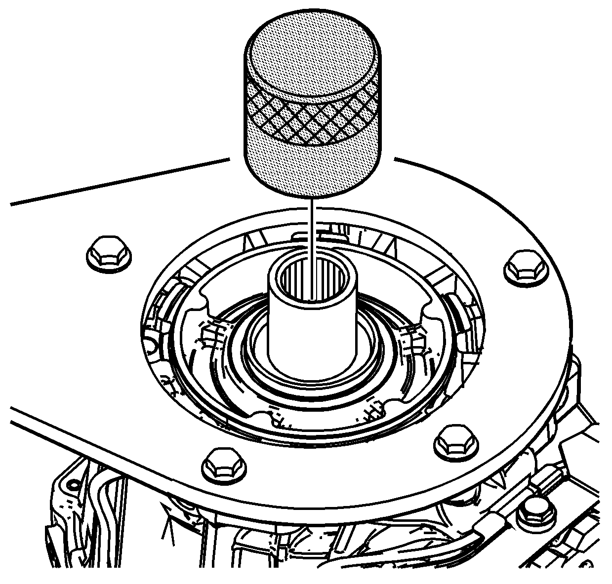
- Using the
J 45934 seal installer
with a hammer, install the input shaft seal.
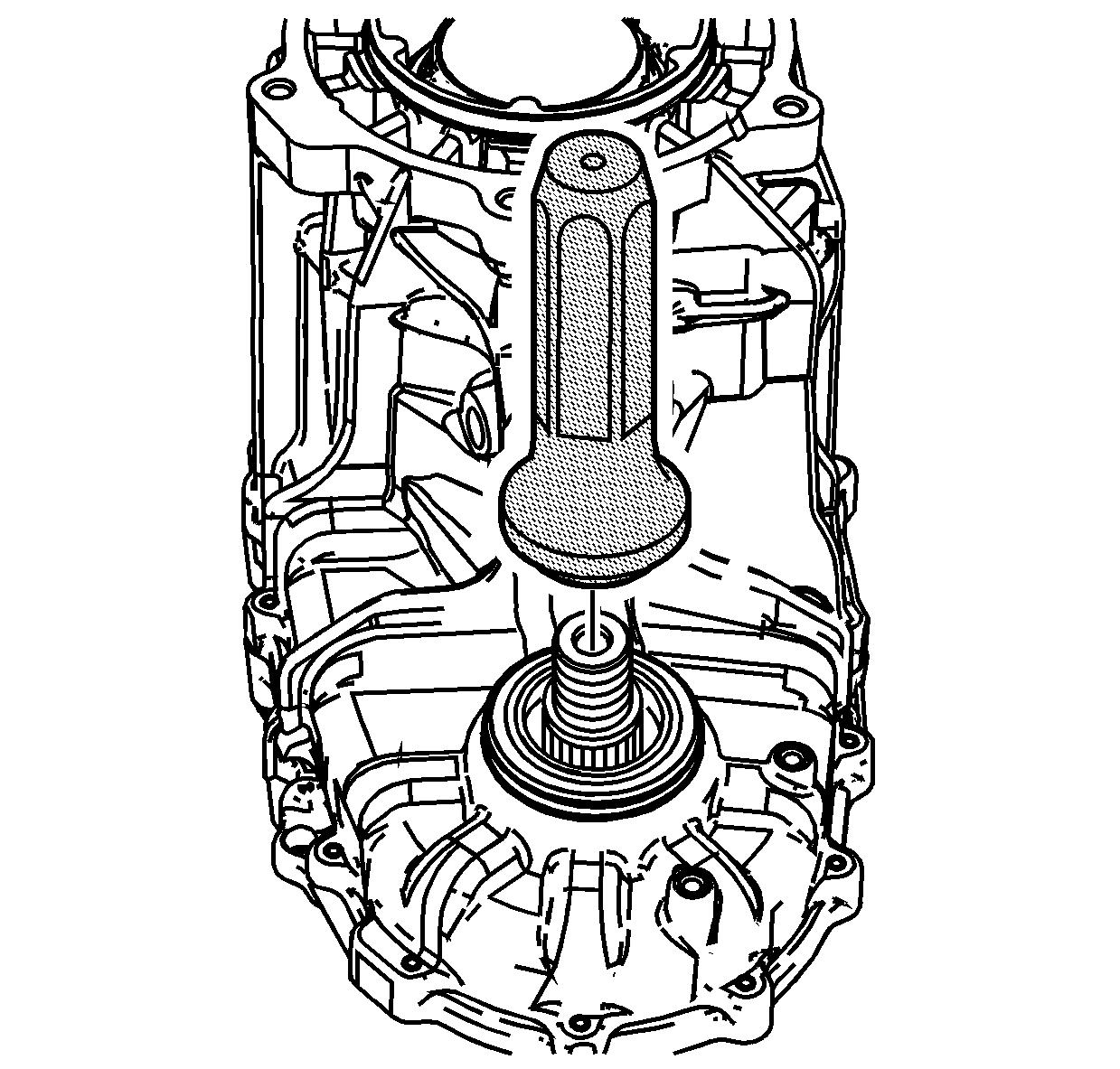
- Using the
J 37212 seal installer
with a hammer, install the front output shaft seal.
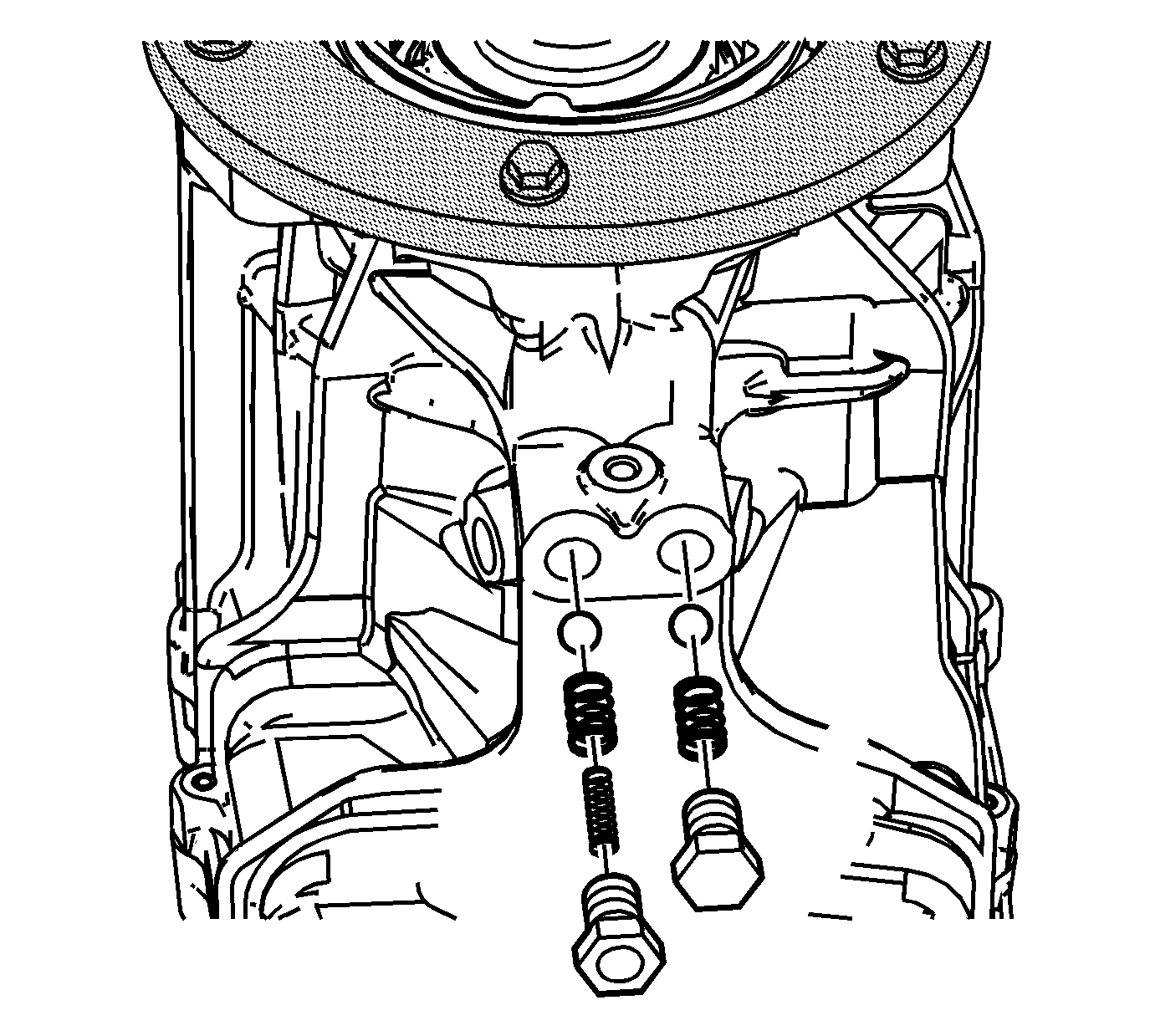
Note: Depending on design levels, this transfer case may or may not have an additional spring nesting inside the high/low shift shaft detent.
- Install the detent springs and balls.
- Apply GM P/N 12346004 (Canadian P/N 10953480) to the threads on the detent plugs.
- Install the detent plugs. Tighten the detent plugs to
19 N·m (14 lb ft).
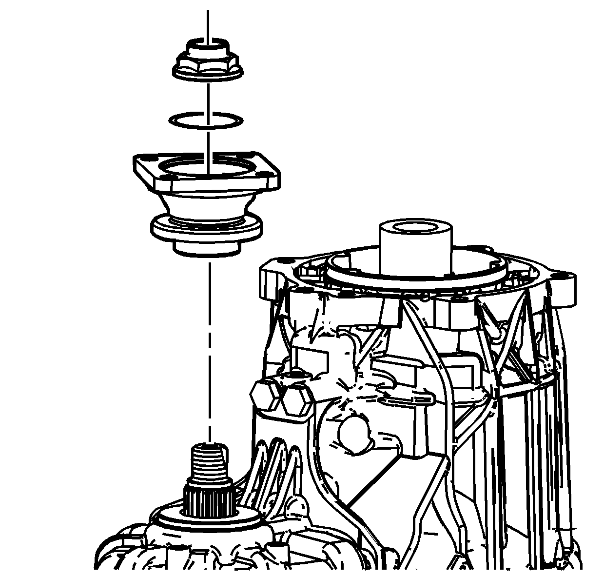
- Install the yoke flange on the front
output shaft.
- Lightly lubricate a new yoke flange O-ring with transfer case fluid.
- Install the yoke flange O-ring.
- Install a new yoke flange nut.
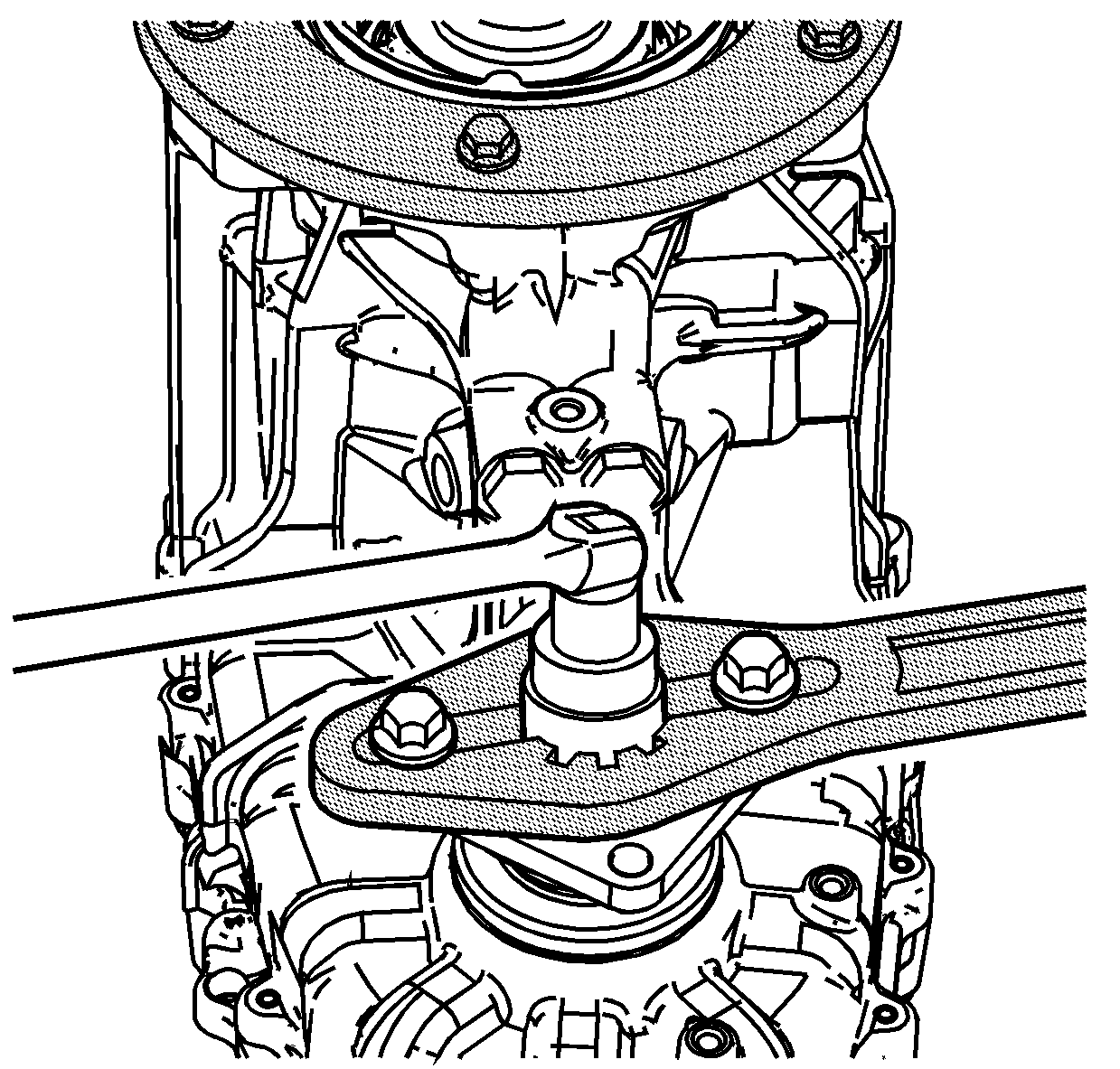
- Install the
J 8614-01 holding tool
to assist in tightening the yoke flange nut. Tighten the yoke flange nut to
137 N·m (101 lb ft).
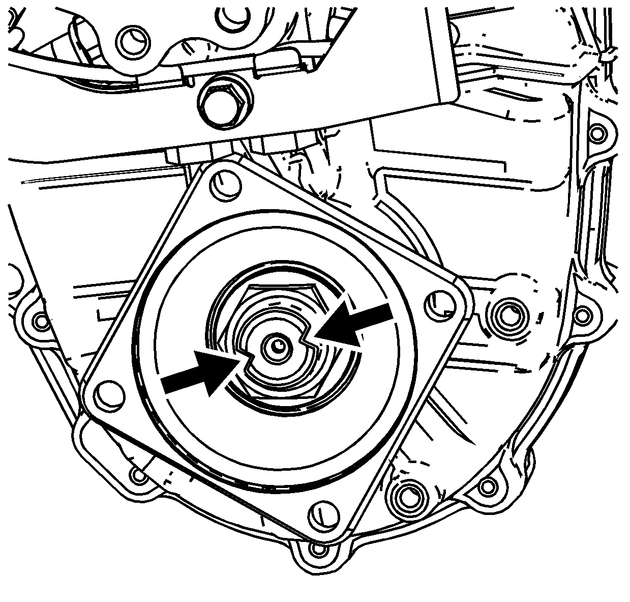
- Remove the
J 8614-01 holding tool
.
- Using a suitable punch, stake the yoke flange nut in 2 places.
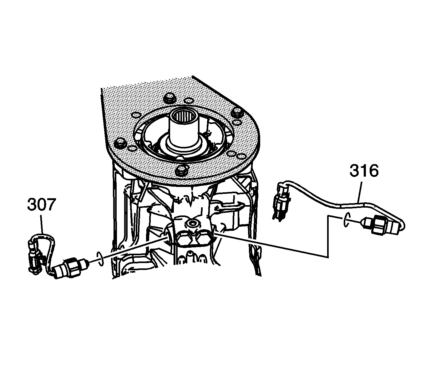
- Install the 2/4 switch assembly (316) with the copper gasket. The
2/4 switch has the gray wiring harness connector. Tighten the 2/4 switch to
39 N·m (29 lb ft).
- Install the NEUTRAL start switch (307) with the copper gasket. The NEUTRAL start switch has the brown wiring harness connector. Tighten the NEUTRAL switch to
39 N·m (29 lb ft).
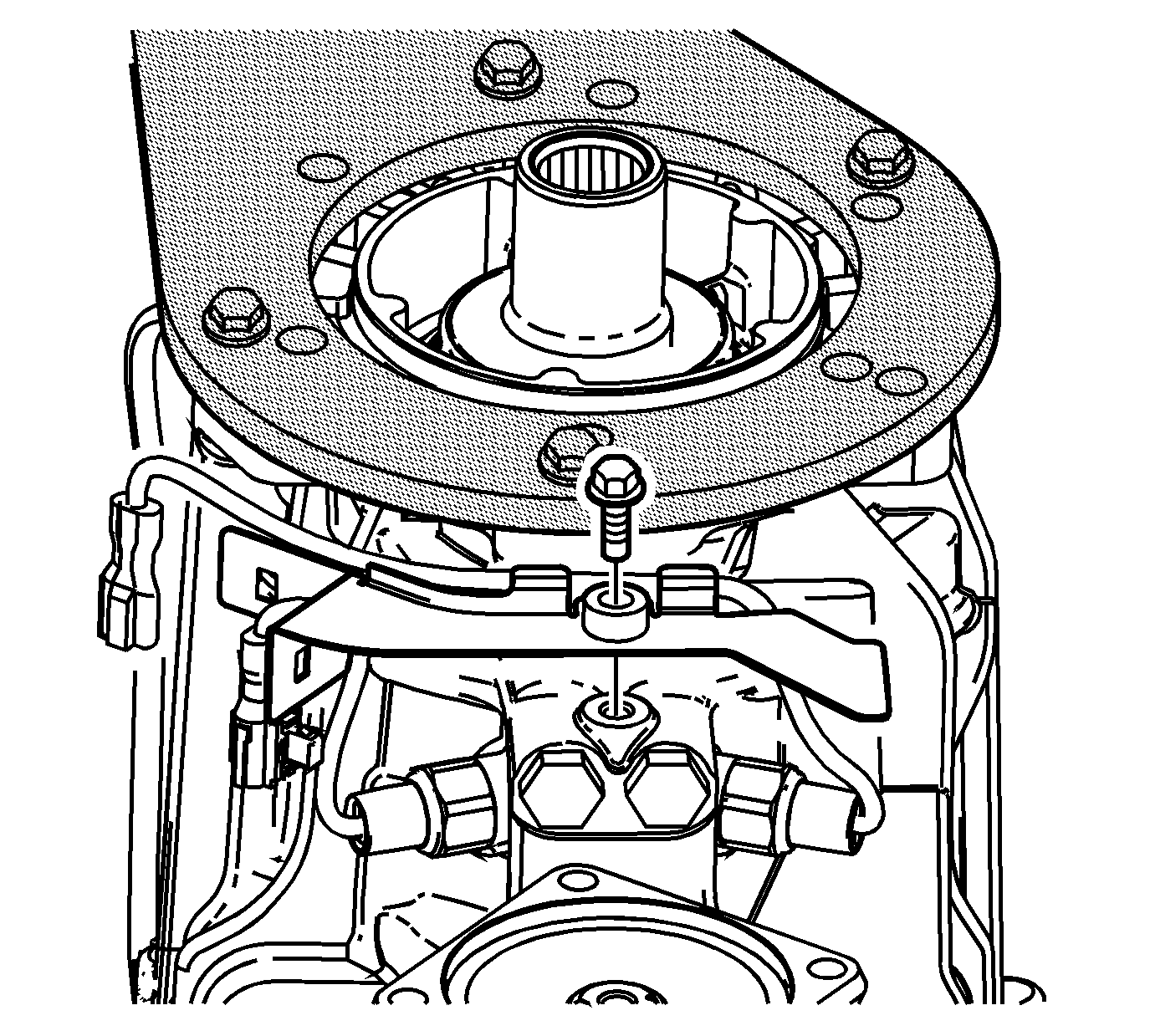
- Install the switch connector bracket
and spacer.
- Install the connector bracket bolt. Tighten the connector bracket bolt to
15 N·m (11 lb ft).
- Install the wiring harness connectors, for the switches, into the switch connector bracket.
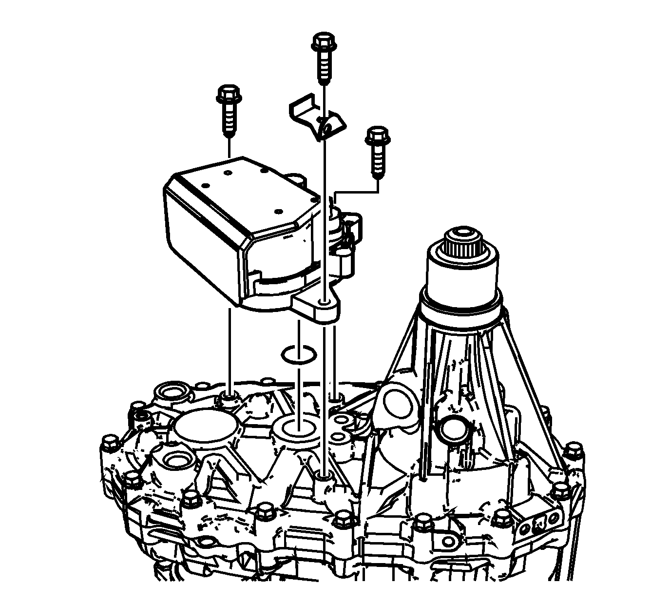
Note: Do not rotate the actuator assembly shaft to align with the control actuator shaft.
- Install the actuator assembly and the new O-ring seal.
- Install the actuator assembly bolts and wire harness bracket. Tighten the actuator assembly bolts to
22 N·m (16 lb ft).
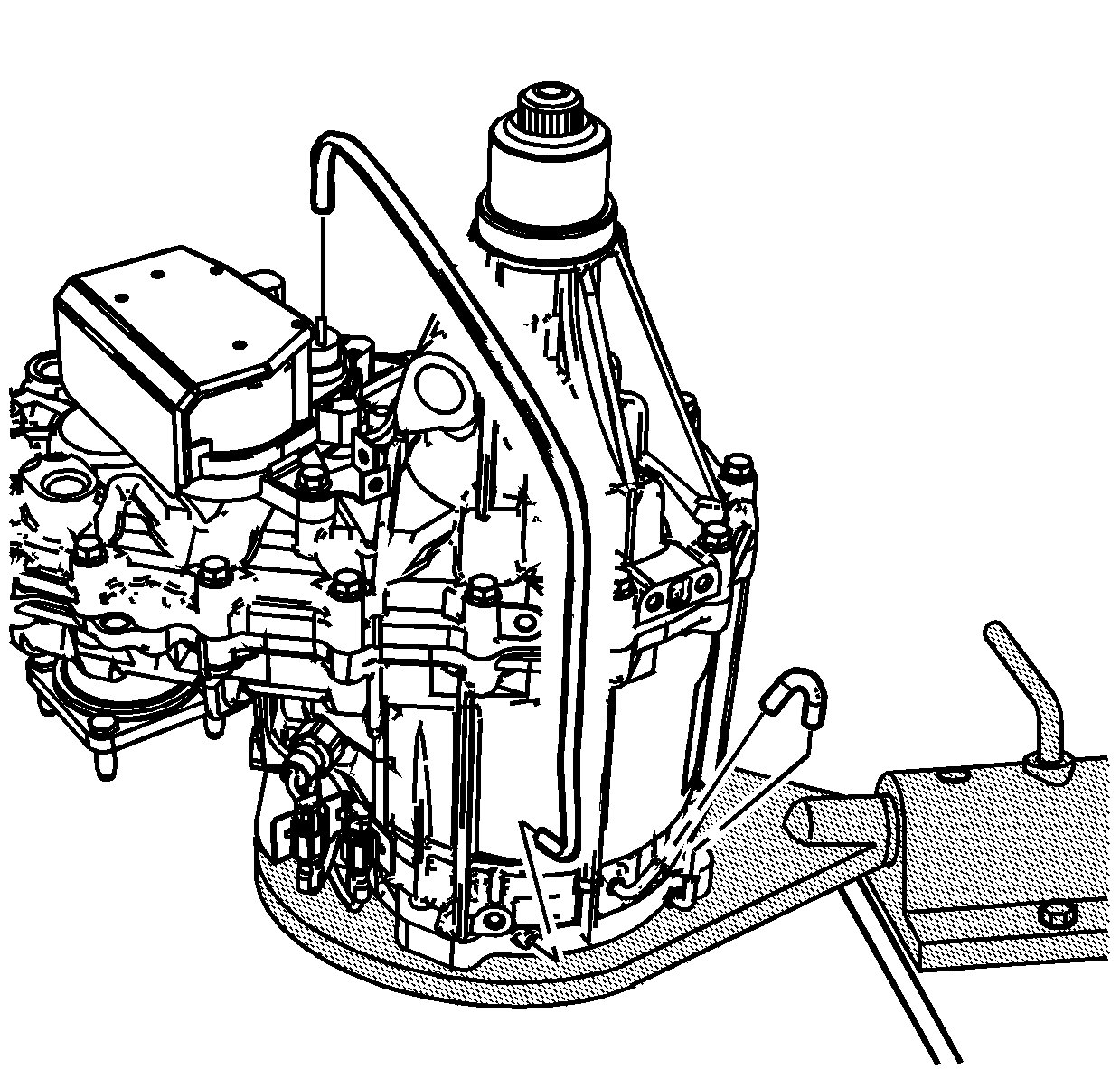
- Install the vent hose to the actuator
assembly.
- Install the breather hose.
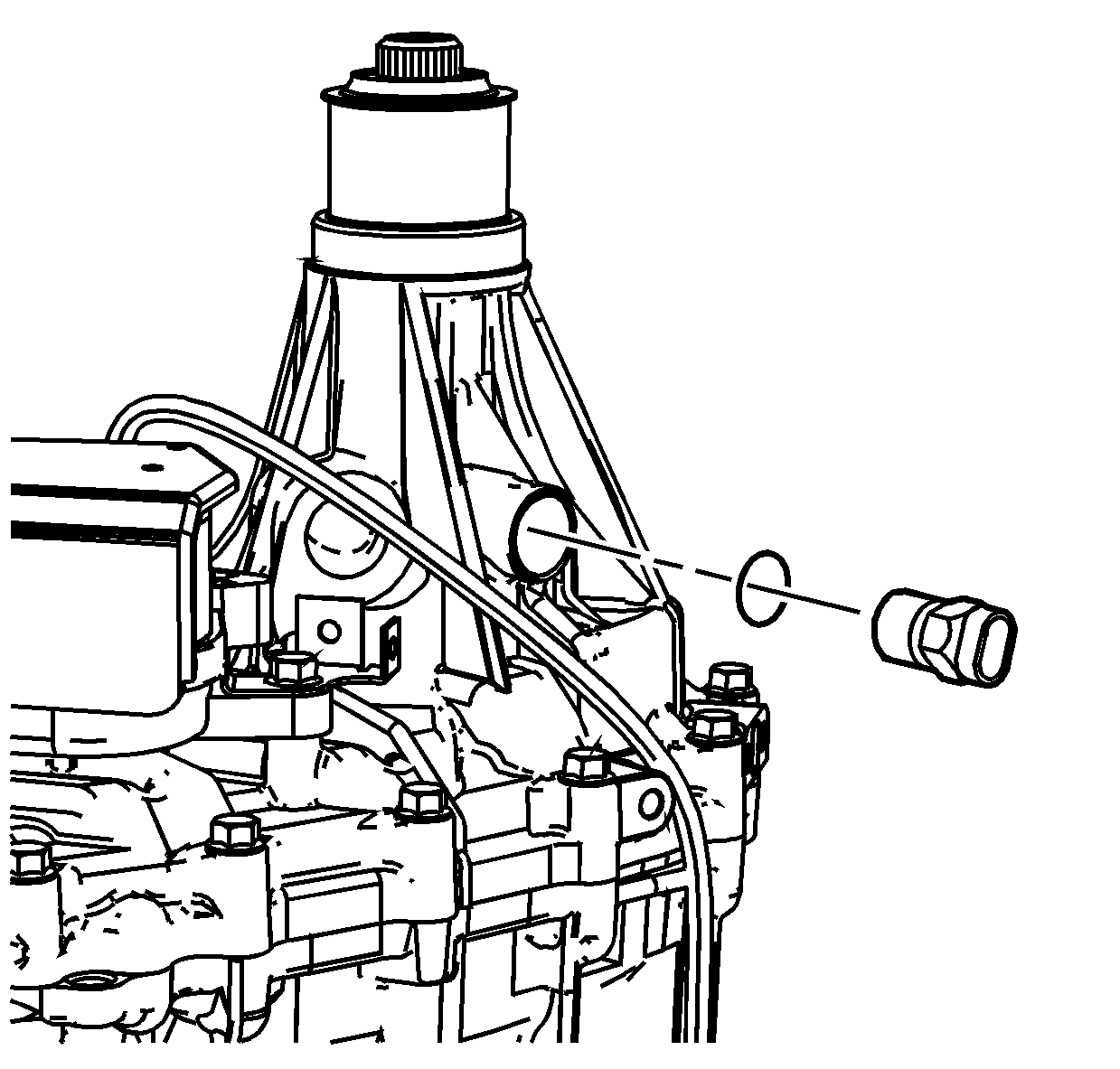
- Install the vehicle speed sensor (VSS) and O-ring
seal. Tighten the VSS to
17 N·m (13 lb ft).
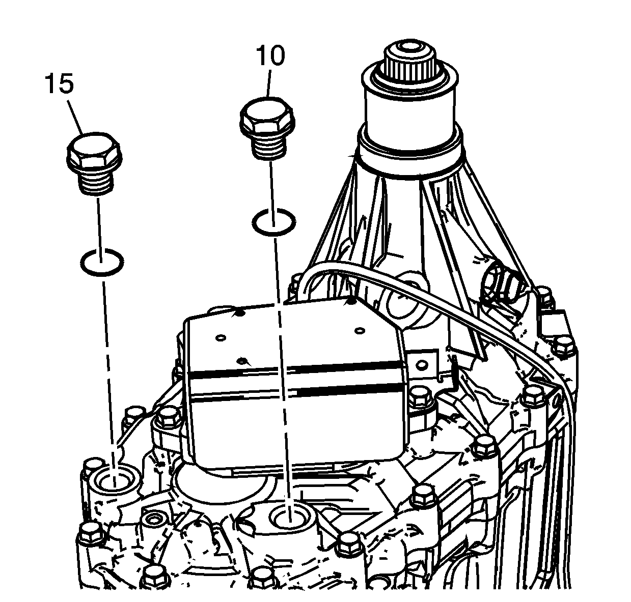
- Install a new O-ring gasket on the drain plug
and the fill plug.
- Install the drain plug (15) and the fill plug (10). Tighten the drain plug and fill plug to
39 N·m (29 lb ft).
- Remove the transfer case from the
J 3289-20 holding fixture
.
- Remove the
J 45759 fixture
from the transfer case.


