For 1990-2009 cars only
Removal Procedure
- Raise and support the vehicle. Refer to Lifting and Jacking the Vehicle .
- Allow the front suspension to hang in the rebound position.
- Mark the adjuster bolt.
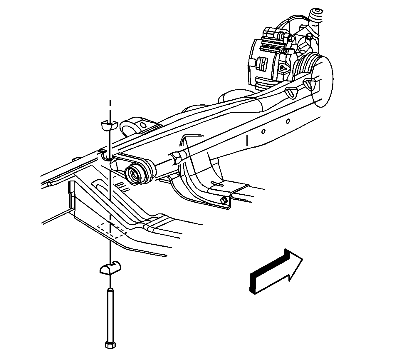
- Remove the adjuster bolt, spacer and adjuster nut.
- Remove the adjustment arms and torsion bars as a unit, moving it rearward to disengage the lower control arm.
Notice: Use care when handling the torsion bars in order to avoid chipping or scratching the coating. Damage to the coating will result in premature failure of the torsion bars.

Important: To aid in re-assembly record the number of turns that are required to remove the adjuster bolt.
Important: Take note that the torsion bars are specific to the left and right sides of the vehicle.
Installation Procedure
- Install the adjustment arms and torsion bars in relation to where the bars were removed.
- Install the adjustment arm to the torsion bar and slide the torsion bar forward until the torsion bar fully engages the lower control arm.
- Install the adjuster bolt, spacer and adjuster nut.
- Lower the vehicle.
- Check the Z-Height. Refer to Trim Height Specifications .

