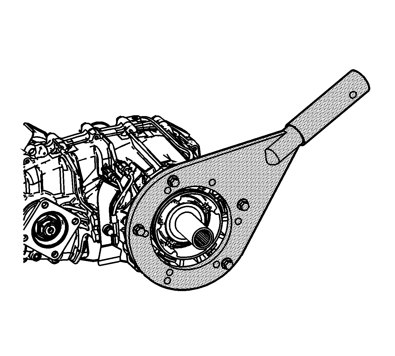
- Install the J 45759
to the transfer case, using 4 suitable bolts.
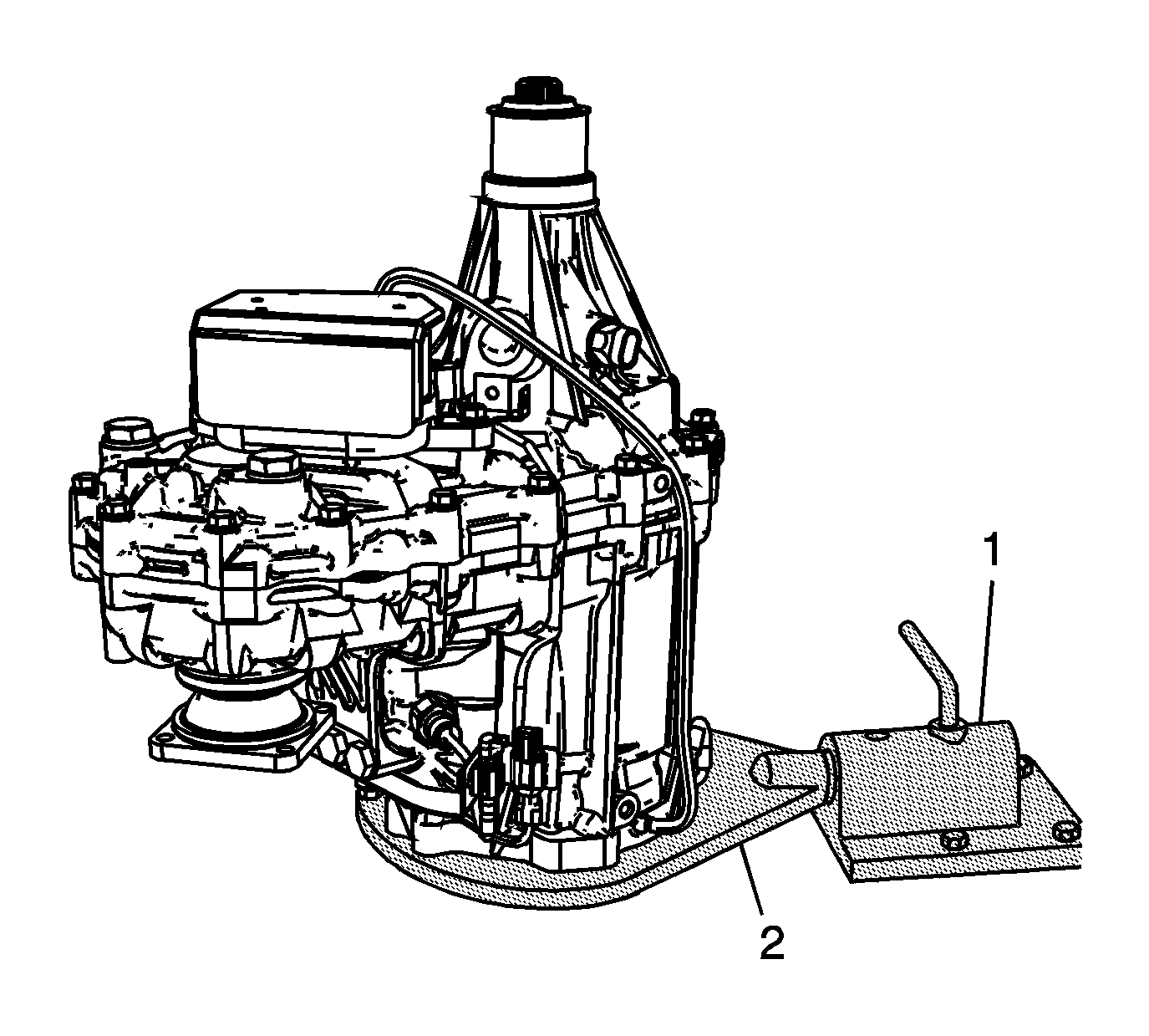
- Mount the J 3289-20
(1) to a sturdy workbench.
- Install the J 45759
(2),
with the transfer case, into the J 3289-20
(1) and secure with the pivot pin.
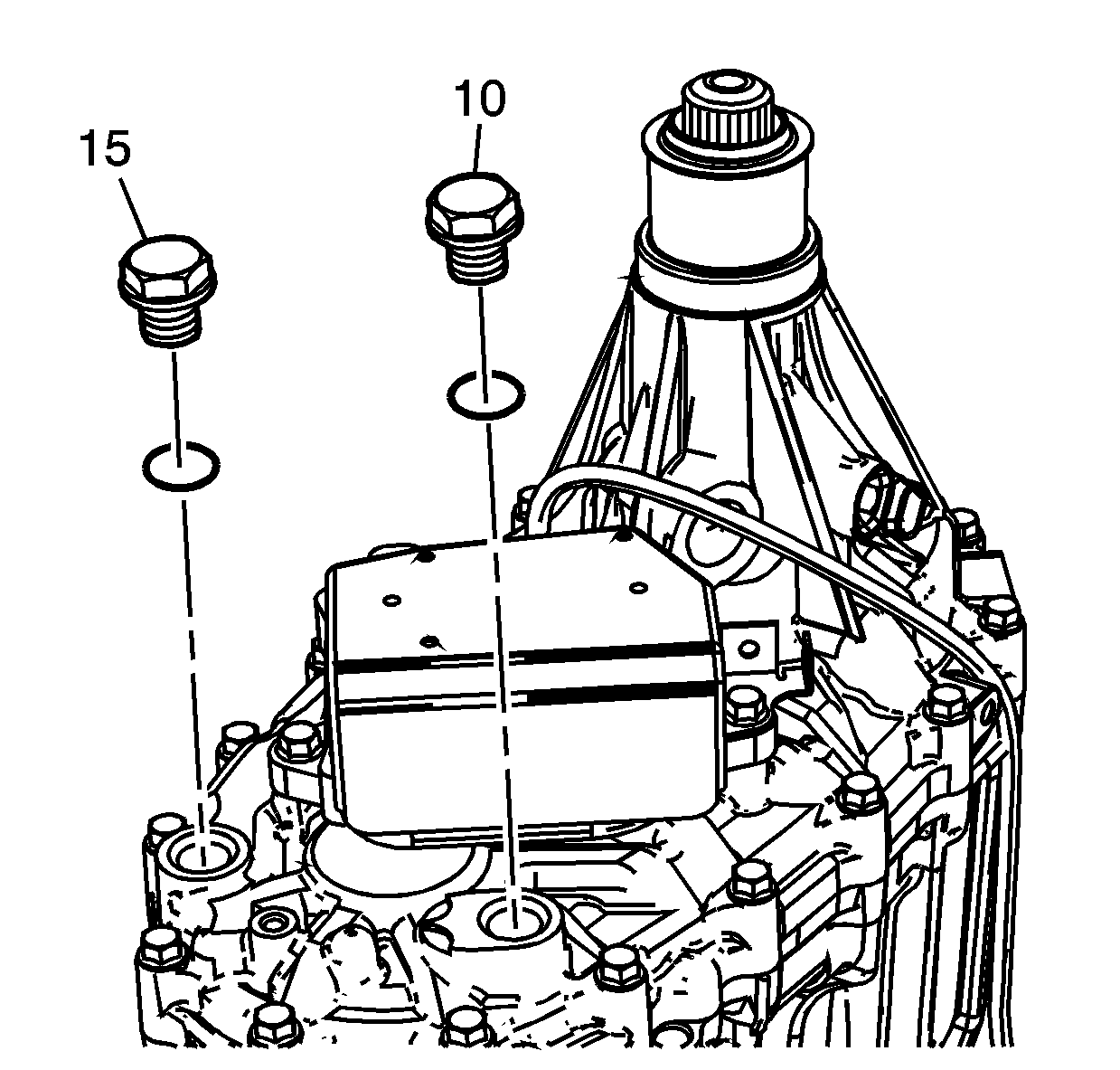
- Remove the drain plug (15) and the
fill plug (10).
- Drain the oil.
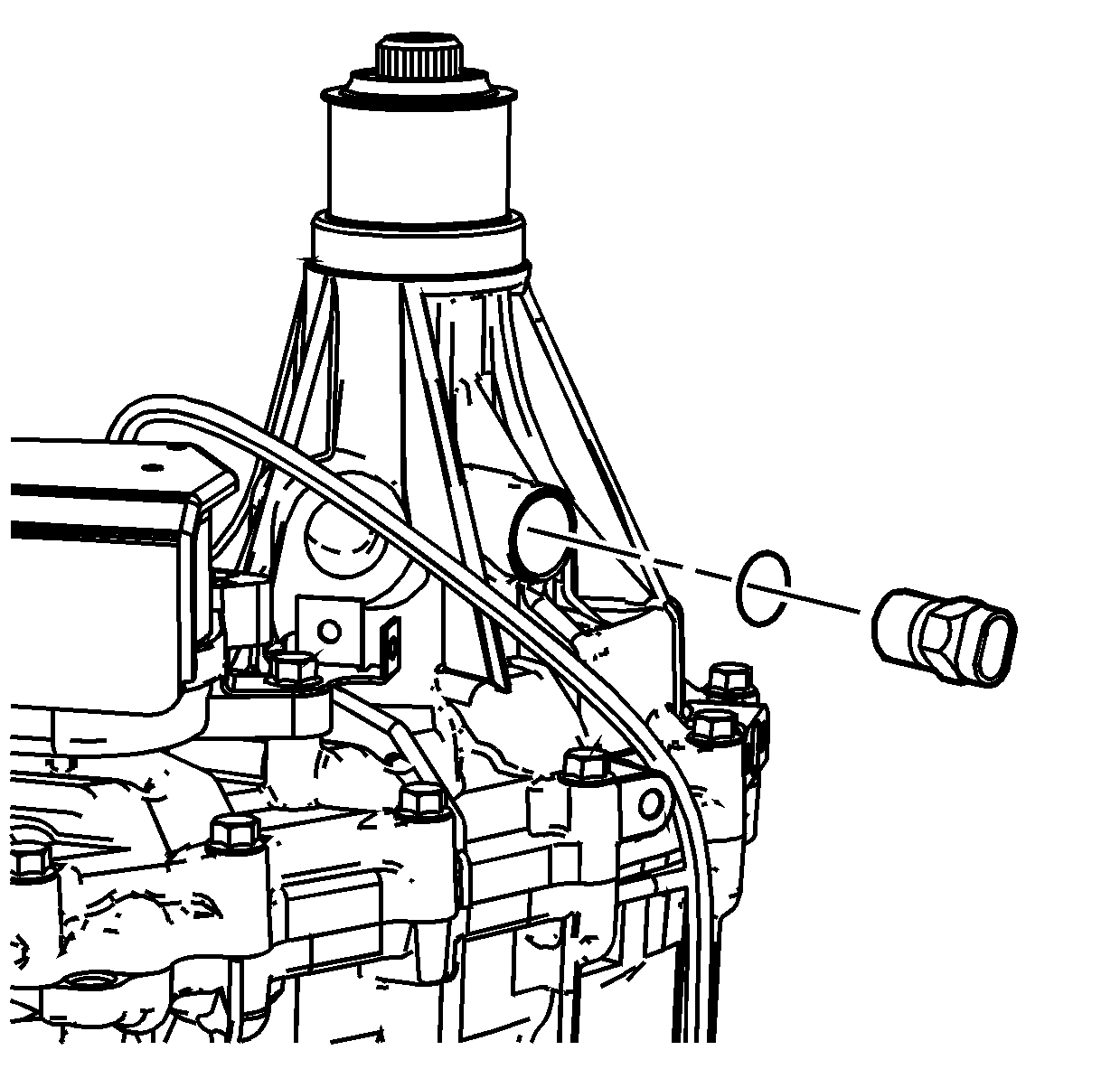
- Remove the vehicle speed sensor and O-ring
seal.
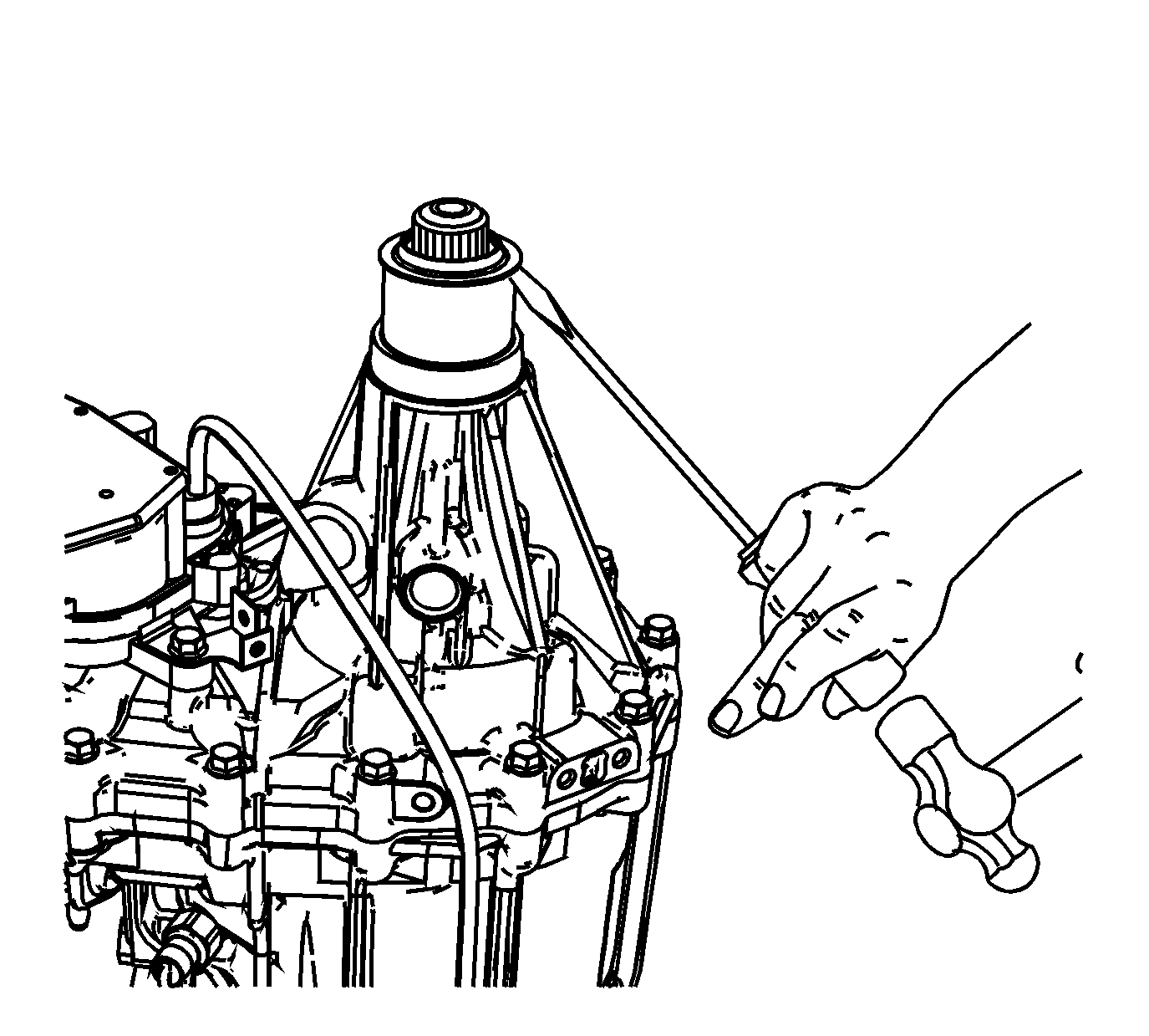
- Remove the rear output shaft seal.
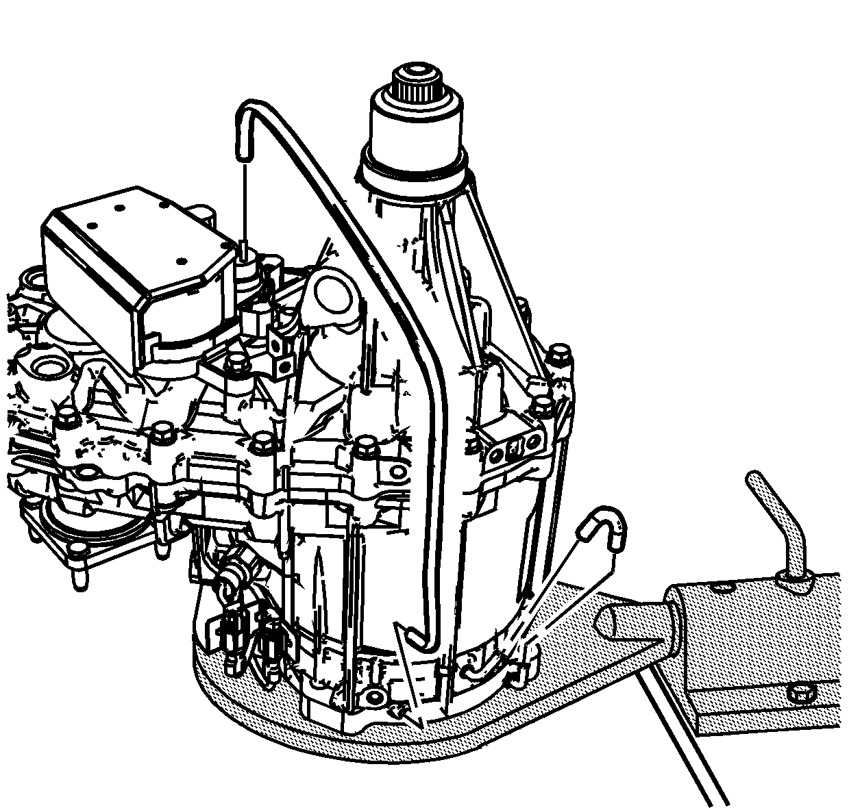
- Remove the vent hose to the actuator assembly.
- Remove the breather hose.
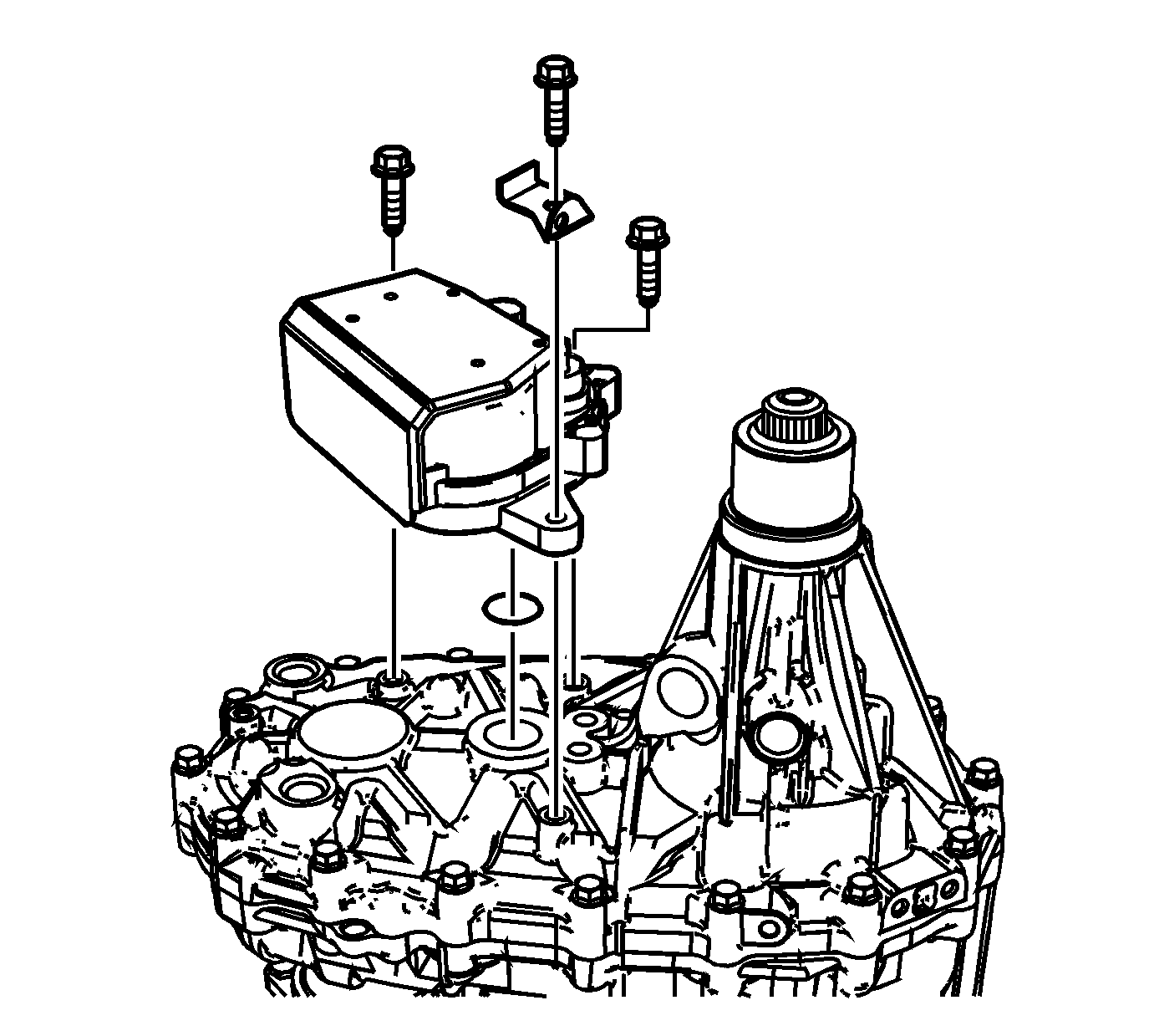
- Remove the actuator assembly bolts and wire
harness bracket.
- Remove the actuator assembly and the O-ring seal.
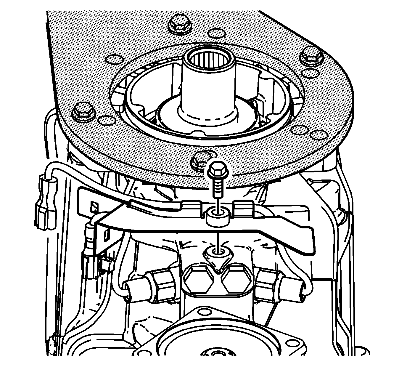
- Remove the wiring harness connectors, for
the switches, from the switch connector bracket.
- Remove the bolt for the connector bracket.
- Remove the connector bracket and spacer.
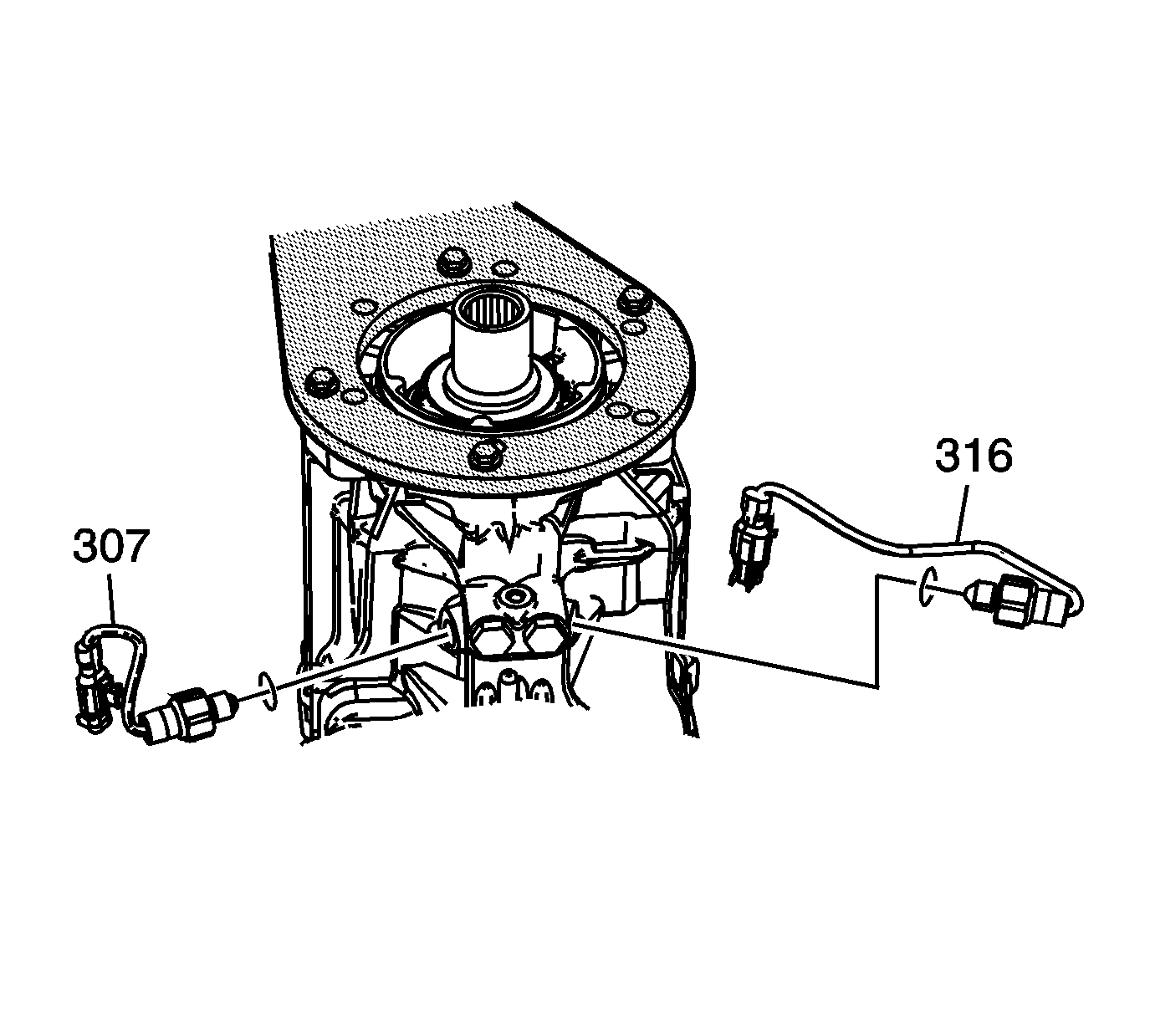
- Remove the 2/4 switch assembly (316)
with the copper gasket. The 2/4 switch has the gray wiring harness connector.
- Remove the NEUTRAL start switch (307) with the copper gasket.
The NEUTRAL start switch has the brown wiring harness connector.
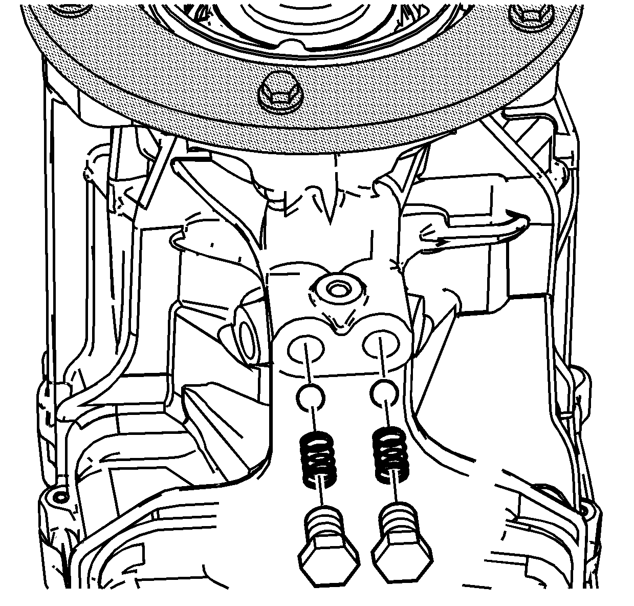
- Remove
the detent plugs, springs and balls.
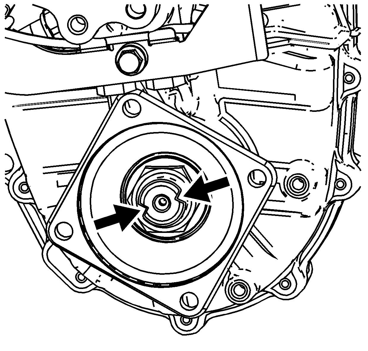
Important: In order to easily remove the nut, ensure
the staked areas are completely bent out from the shaft.
- Using a suitable punch, bend the stakes out on the yoke flange nut.
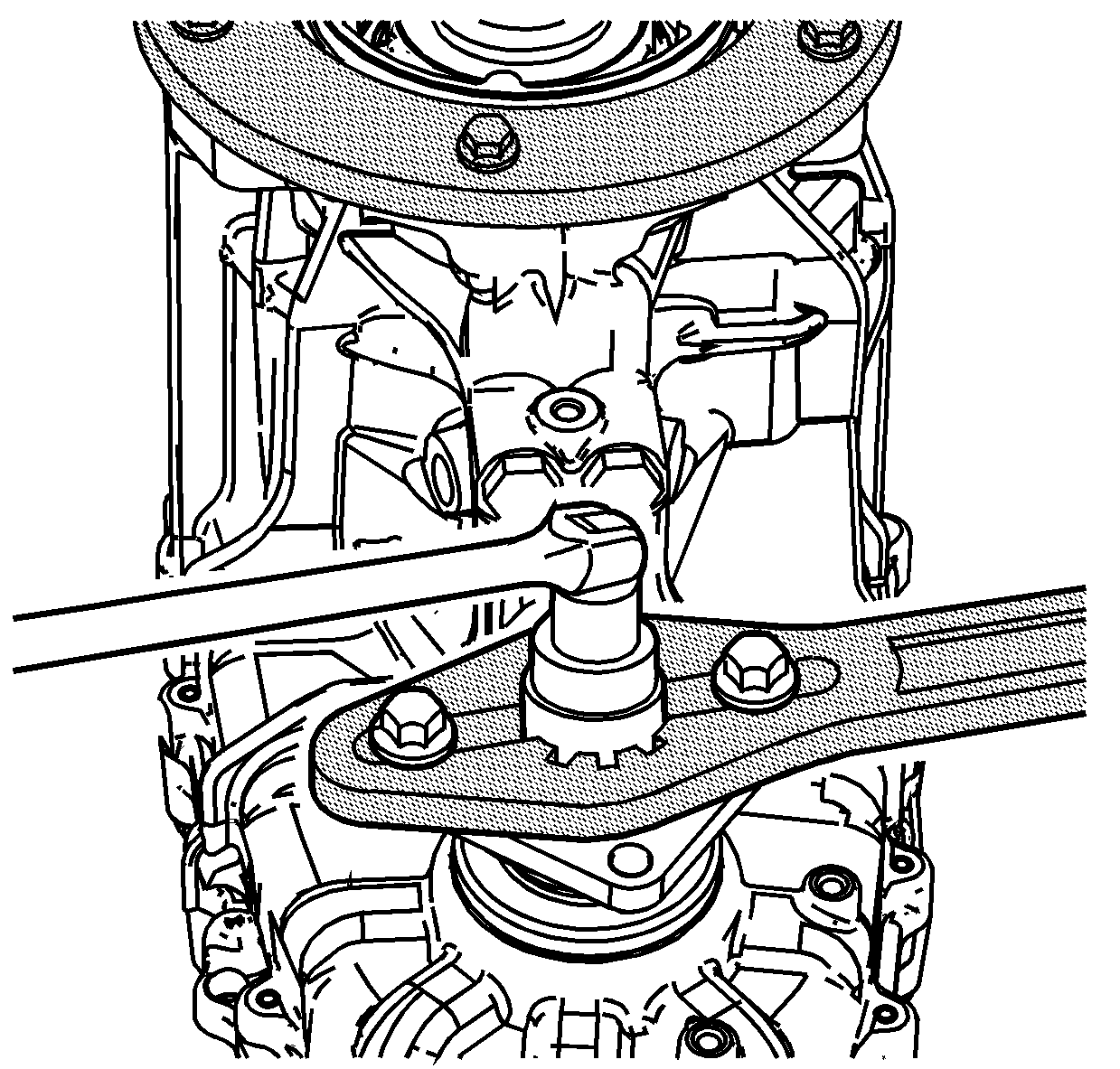
- Using the J 8614-01
, loosen the yoke flange nut.
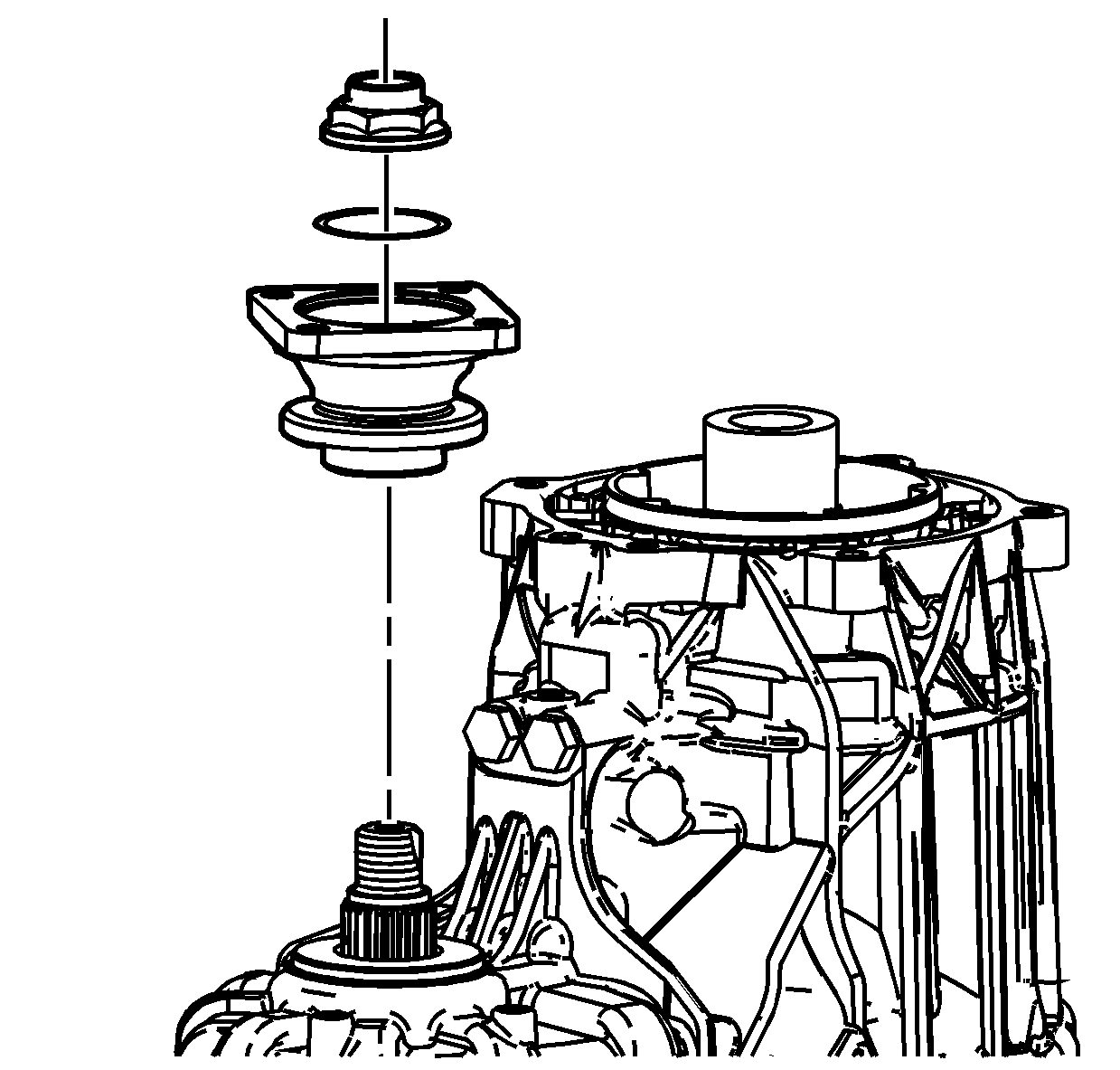
- Remove the yoke flange nut, the O-ring
seal, and the front output yoke flange.
- Discard the nut and O-ring seal after removal.
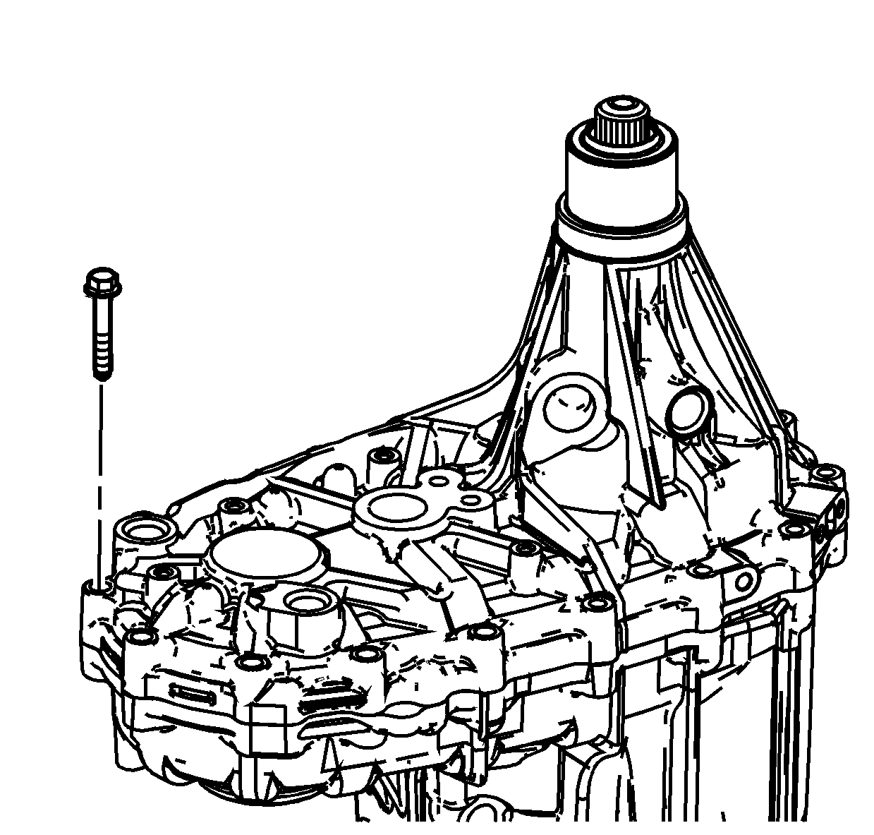
- Remove the case half bolts.
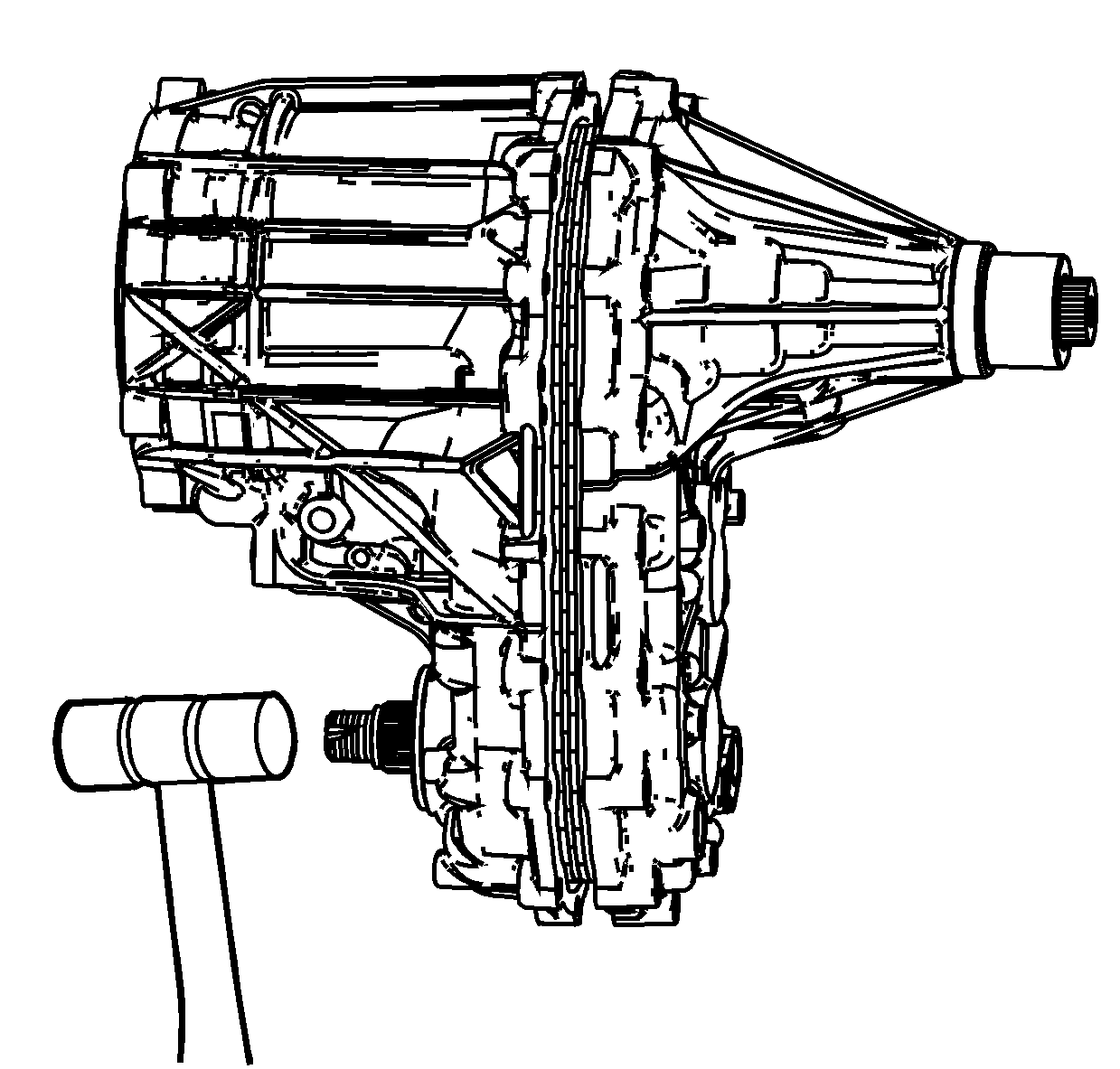
- Using a soft face hammer on the rear case
half, shear the case half sealer.
- Using a soft face hammer on the end of the front output shaft, separate
the case halves.
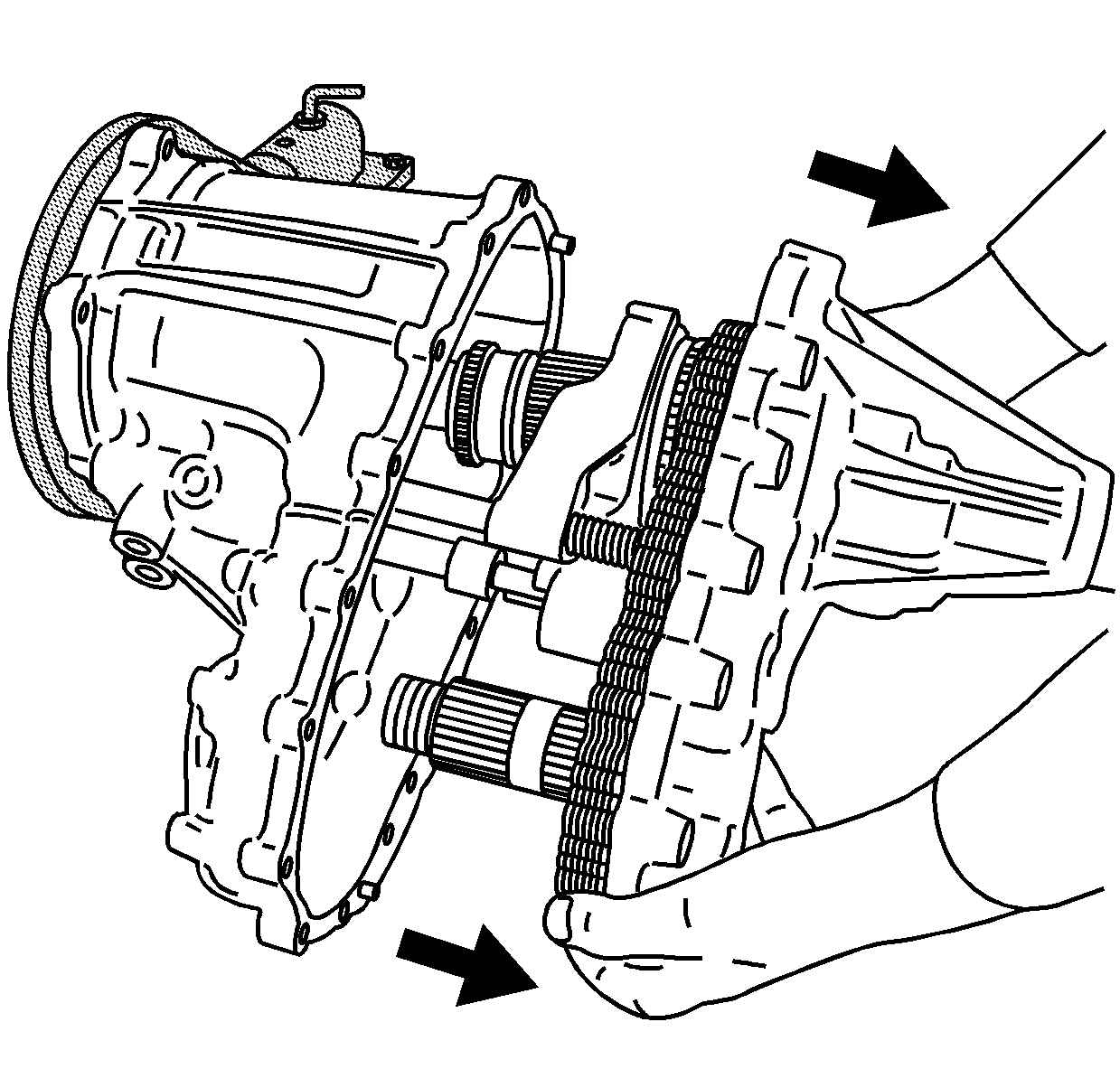
Important: Hold the rear case half straight to the front
case when removing. It may be necessary to reach in and hold the shift forks in position.
Watch for pieces to fall out of the cases, if not removed straight and if the shift
forks bind.
- Carefully remove the rear case half from the front case half. Only the input
shaft, with the planetary carrier assembly, will remain in the front case half.
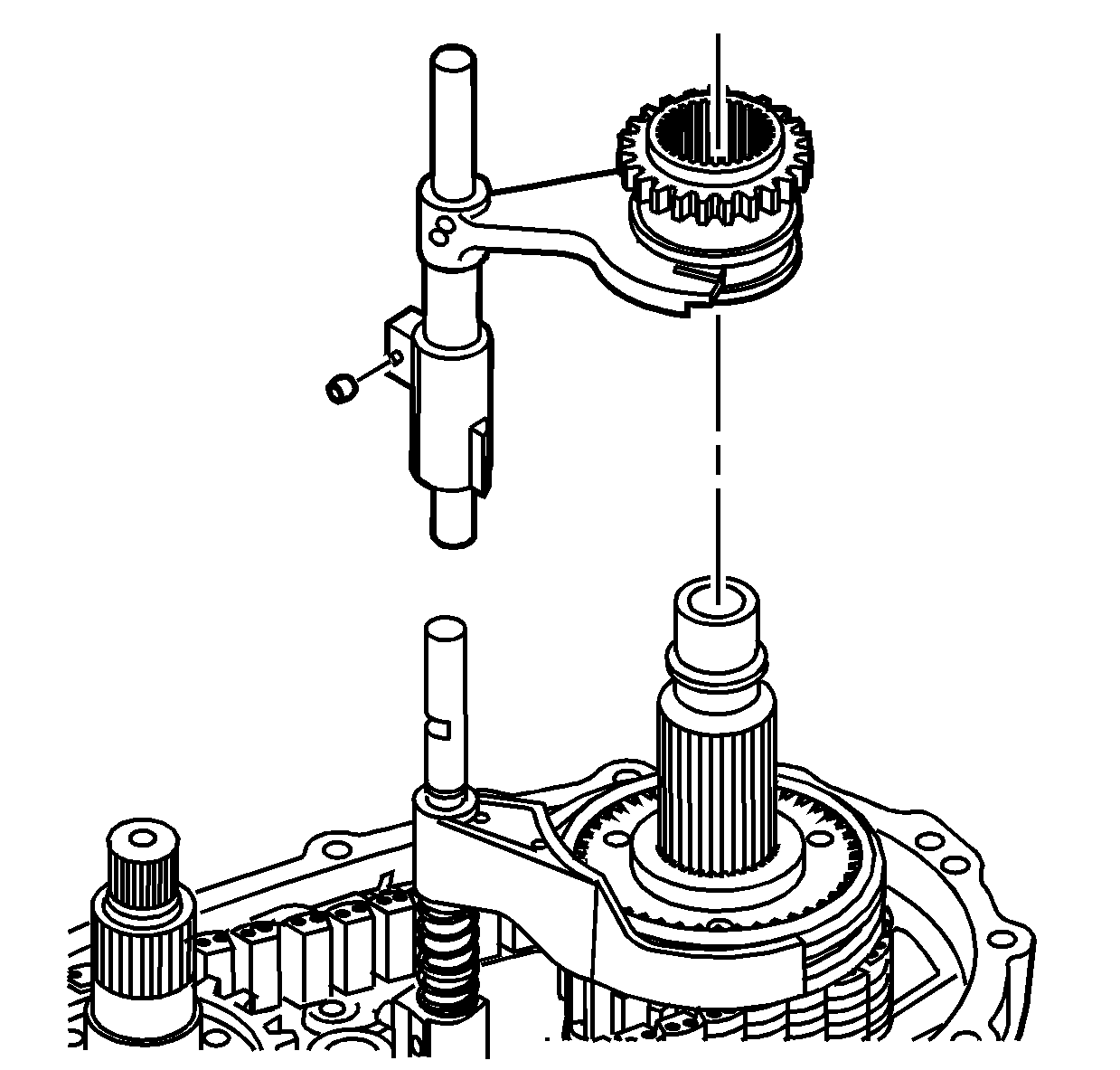
- Remove the high/low shift fork, with the
high/low range sleeve and fork, from the output shaft.
| • | The 2/4 synchronizer sleeve may have to be moved forward. |
| • | The roller on the shift fork may fall off because it is not fastened. |
- Remove the high/low shift fork from the range sleeve.
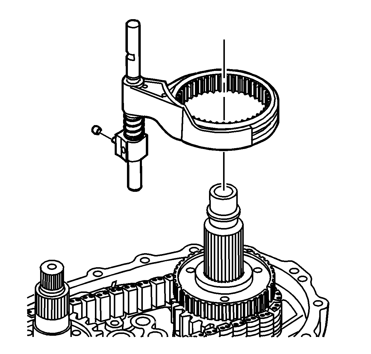
- Remove the 2/4 wheel drive shift fork, and
the 2/4 wheel drive synchronizer sleeve. The roller on the shift fork may fall off
because it is not fastened.
- Remove the shift fork from the sleeve.
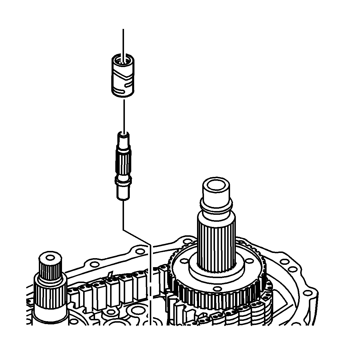
- Remove
the control actuator shaft and the cam.
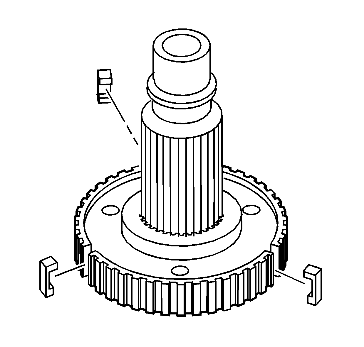
- Remove the 2/4 wheel drive synchronizer
inserts from the synchronizer hub.
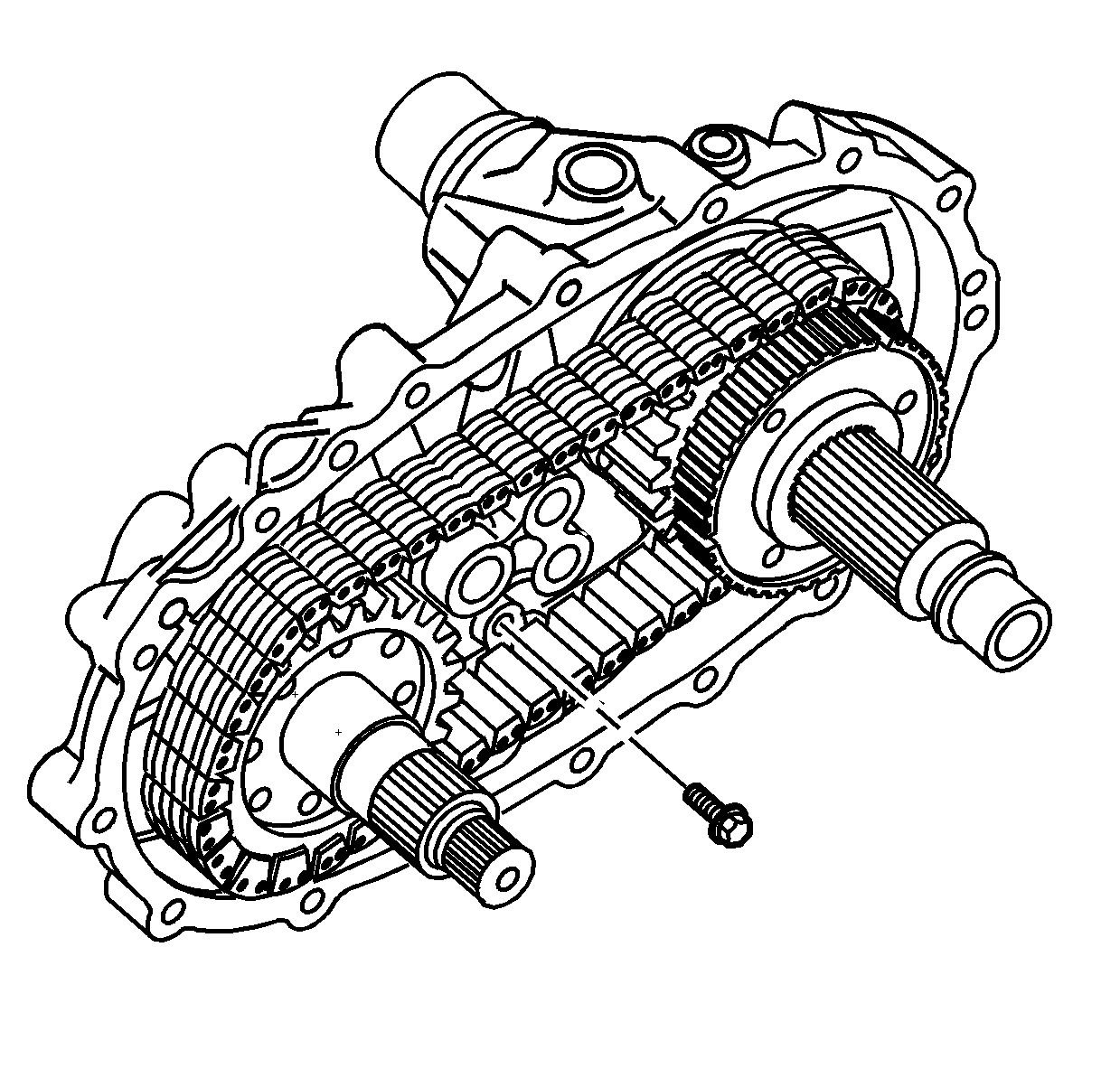
- Remove the bolt retaining the oil pump pick-up
tube.
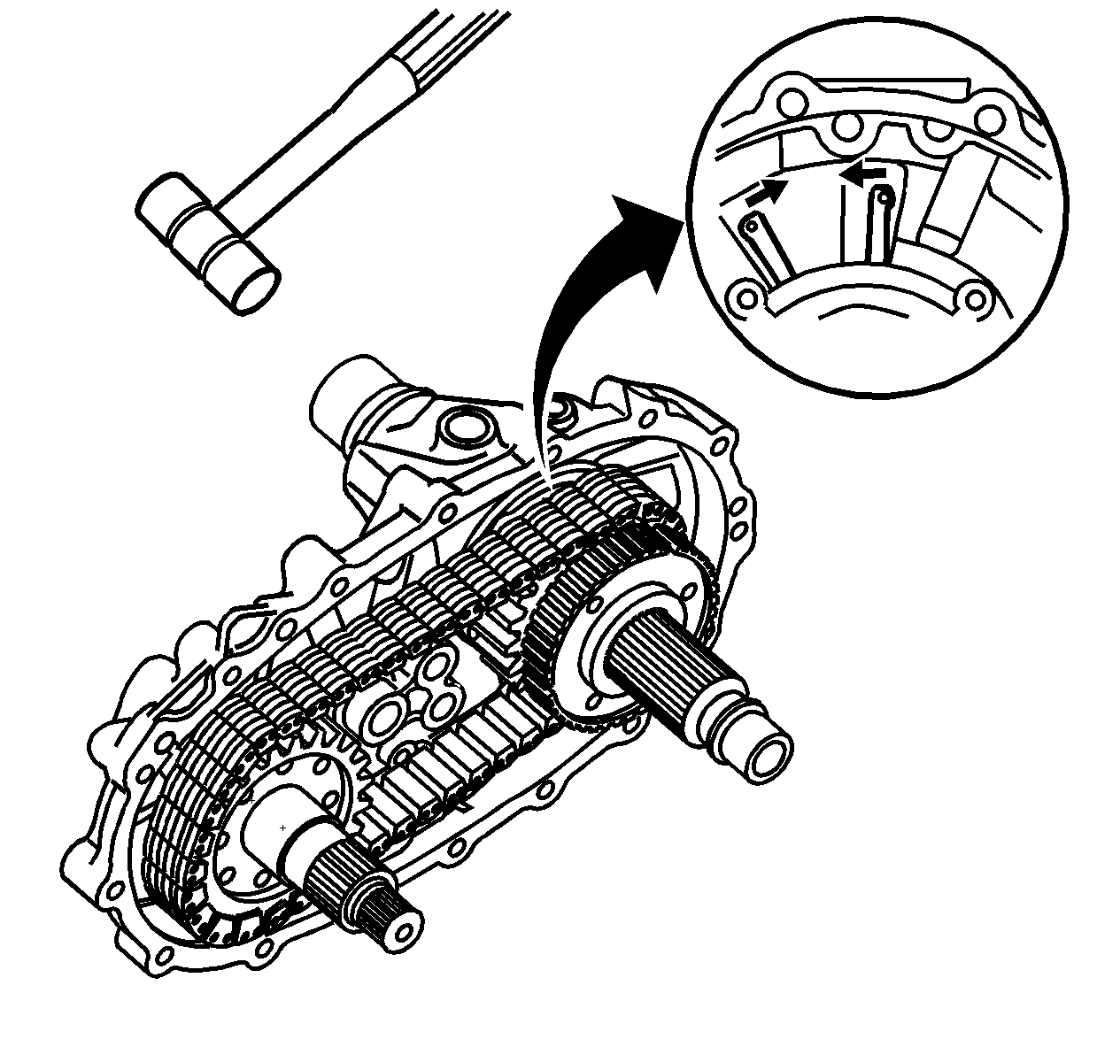
- Using snap ring pliers, squeeze together
the retaining ring for the rear output shaft rear bearing.
- Using a soft face hammer on the rear output shaft, remove the rear output
shaft assembly until the rear output shaft bearing is just out of the case.
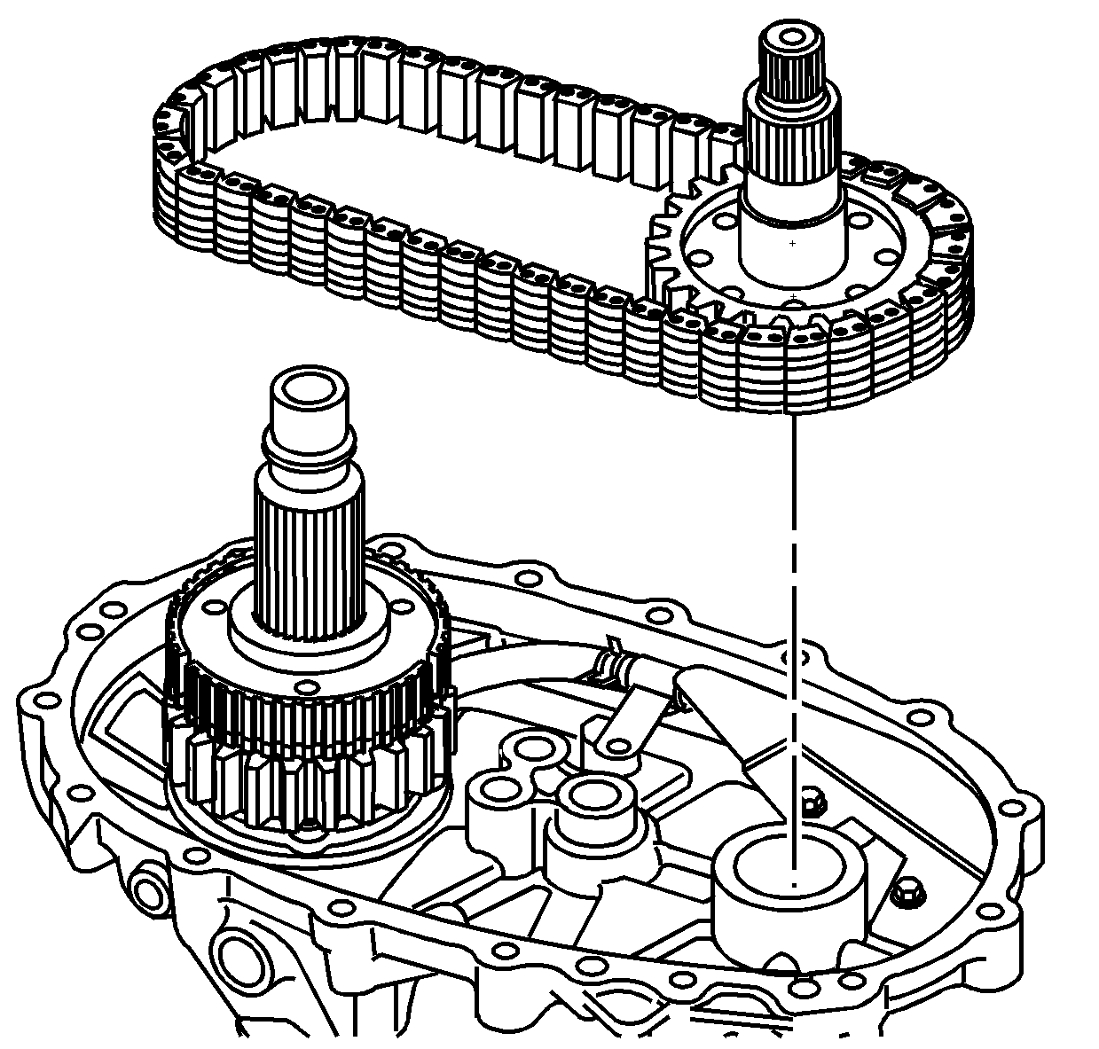
- Remove the front output shaft and the drive
chain.
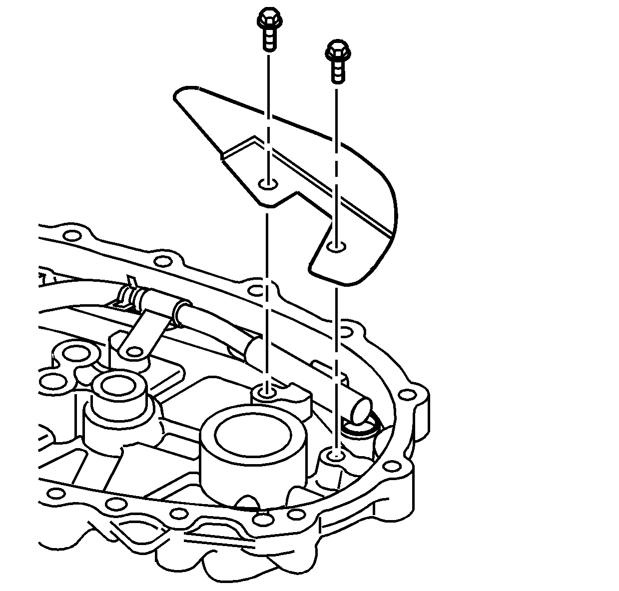
- Remove the bolts and the oil deflector.
- Remove the rear output shaft assembly completely from the rear case half.
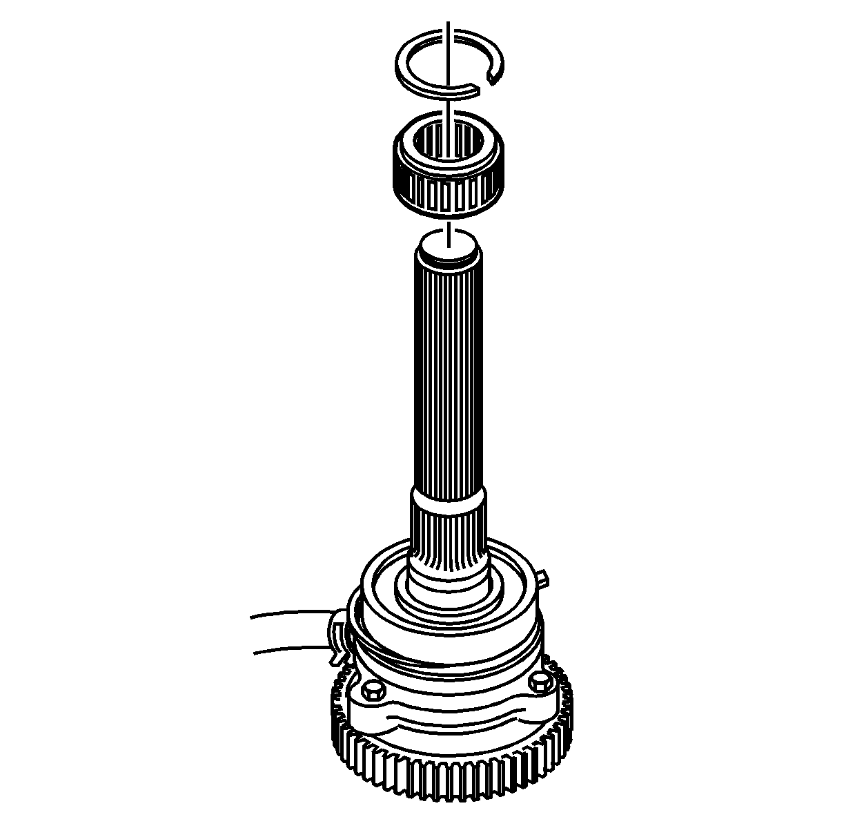
- Remove the rear output shaft retaining ring.
- Remove the speed sensor reluctor wheel.
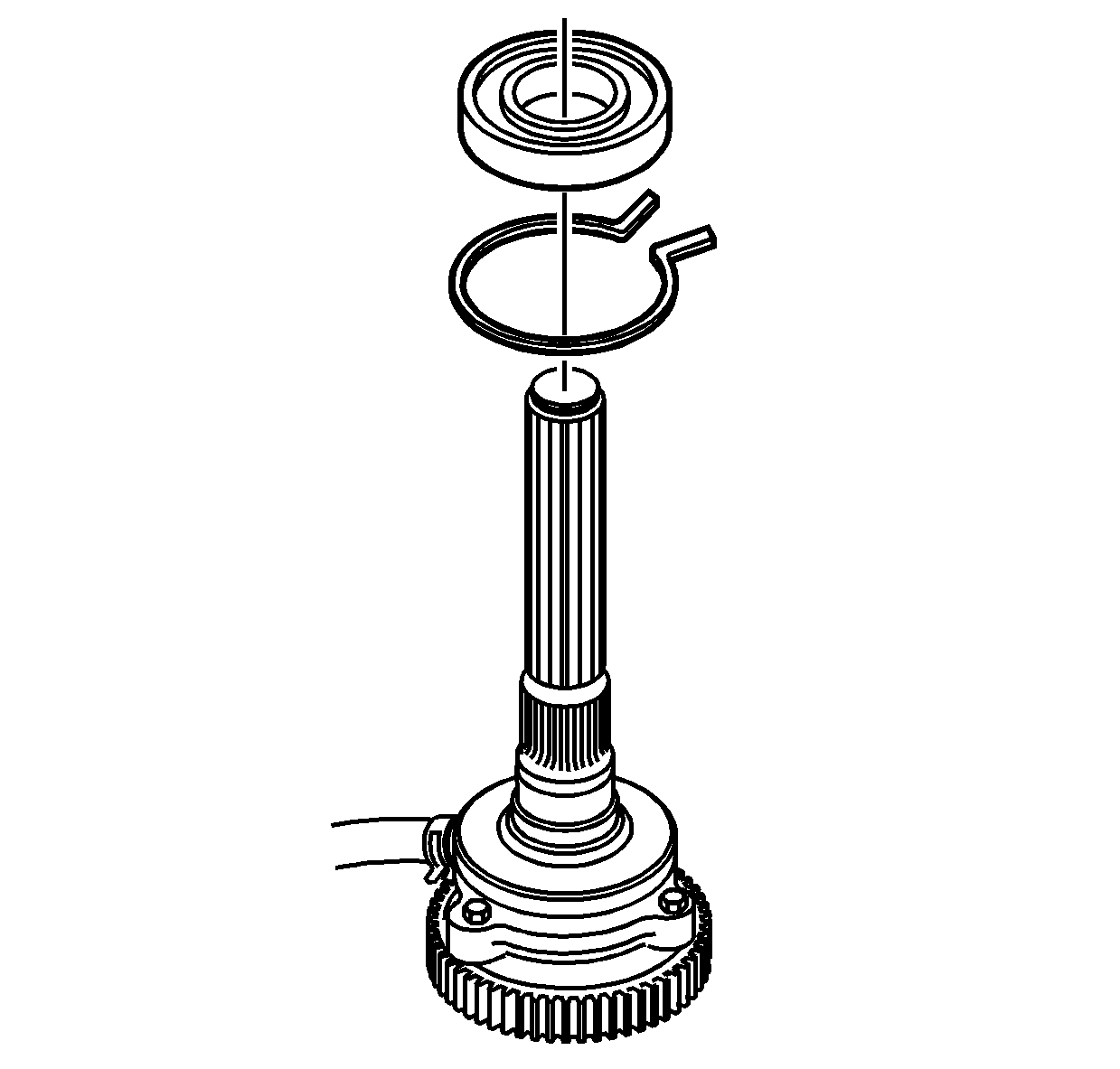
- Remove the rear output shaft bearing.
- Remove the rear output shaft bearing outer retaining ring.
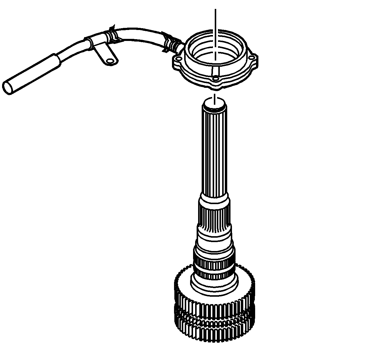
- Remove the oil pump assembly with suction
hose.
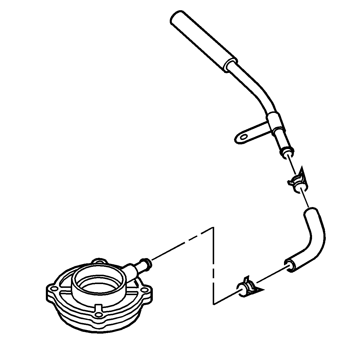
- Remove the oil pump suction hose from the
oil pump.
- Remove the oil pump suction hose from the oil pump screen.
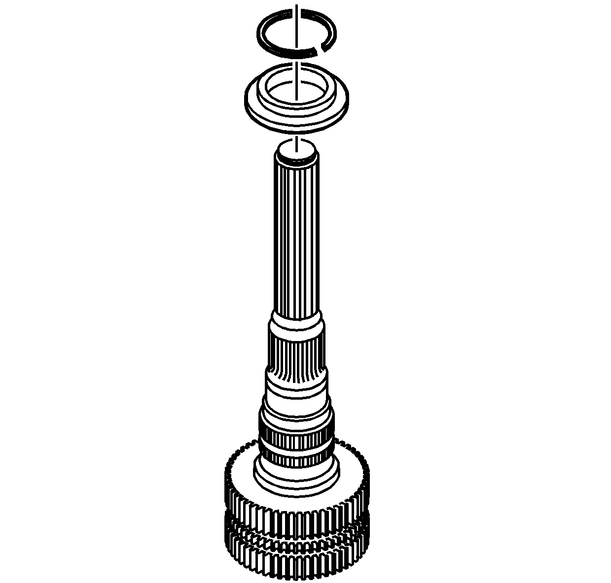
- Remove the drive sprocket retaining ring.
- Remove the drive sprocket thrust washer.
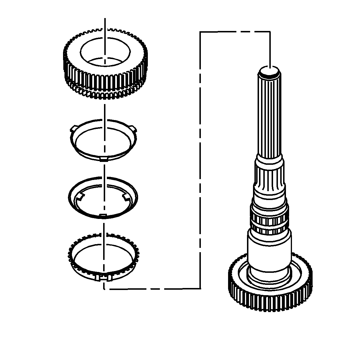
- Remove the drive sprocket.
- Remove the synchronizer blocking ring, middle ring and inner ring.
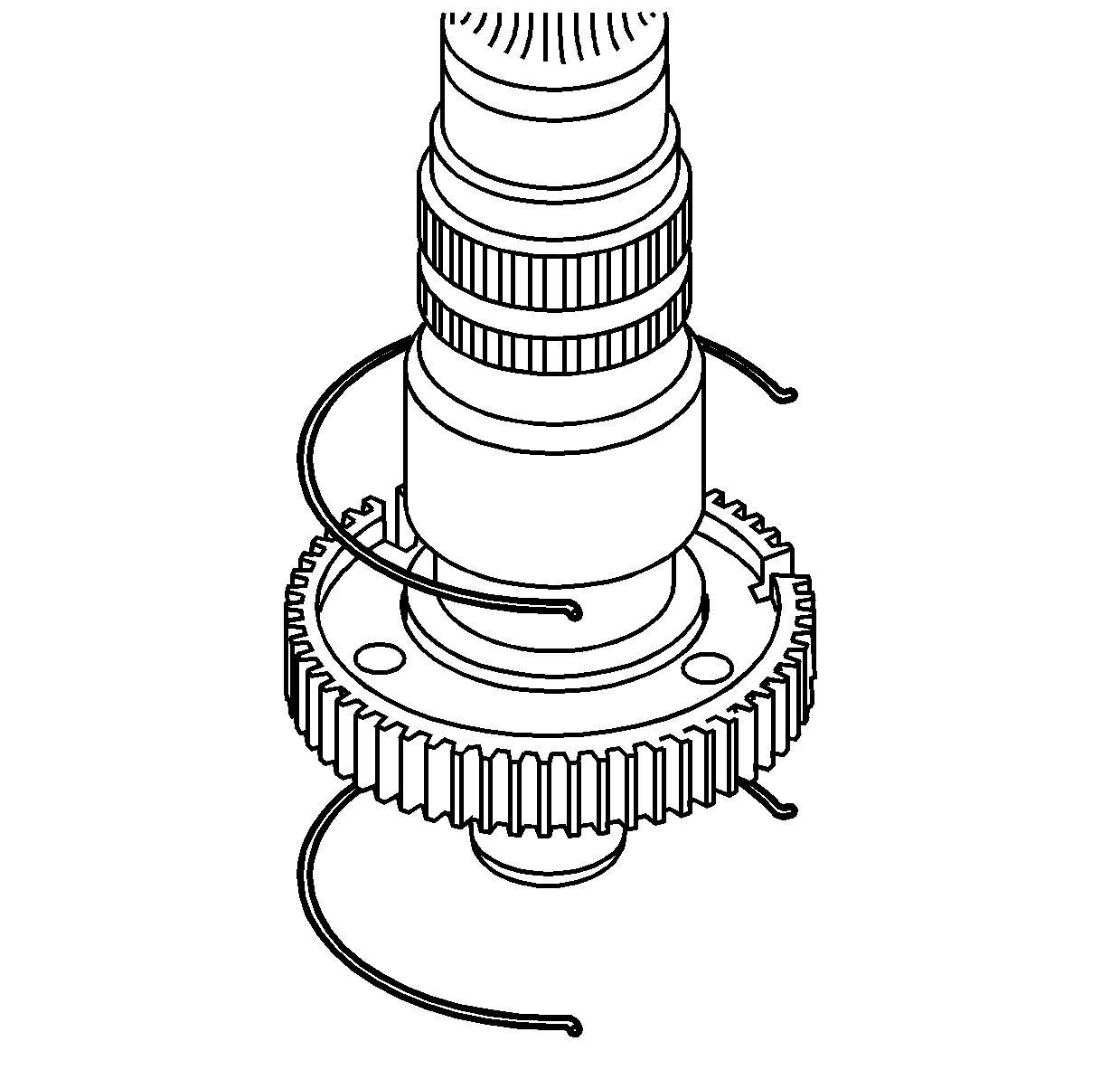
- Remove the springs from the synchronizer
hub.
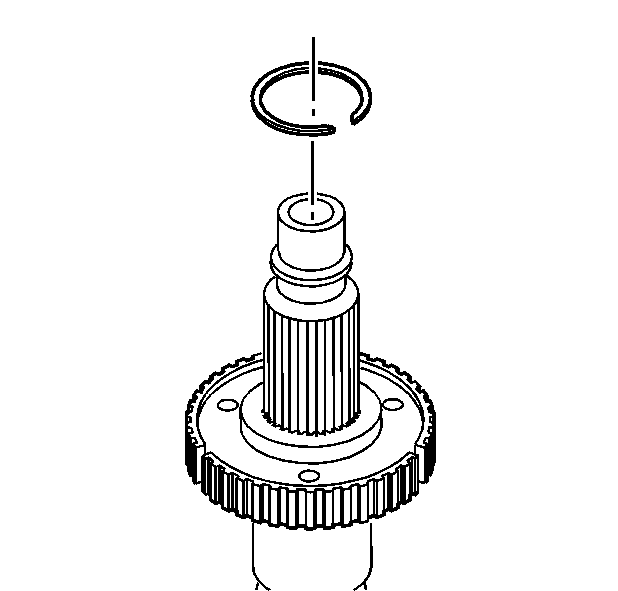
- Remove the synchronizer hub retaining ring.
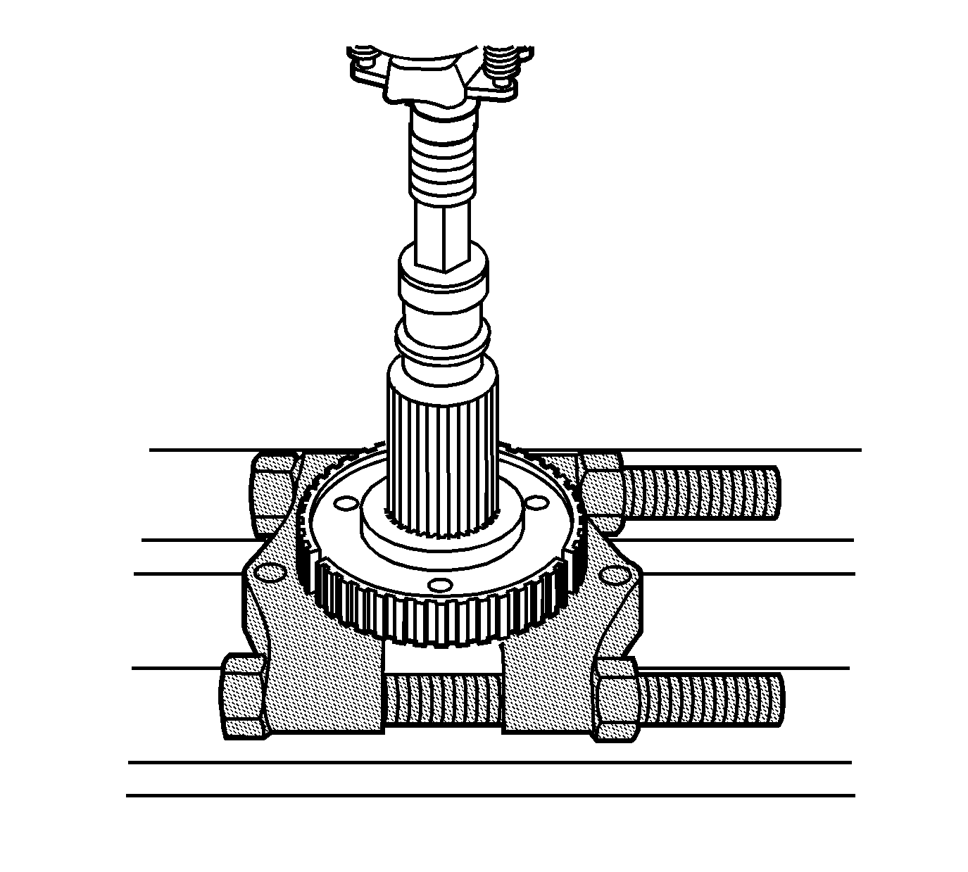
- Using a hydraulic press and the J 22912-B
, remove the synchronizer hub from the rear
output shaft.
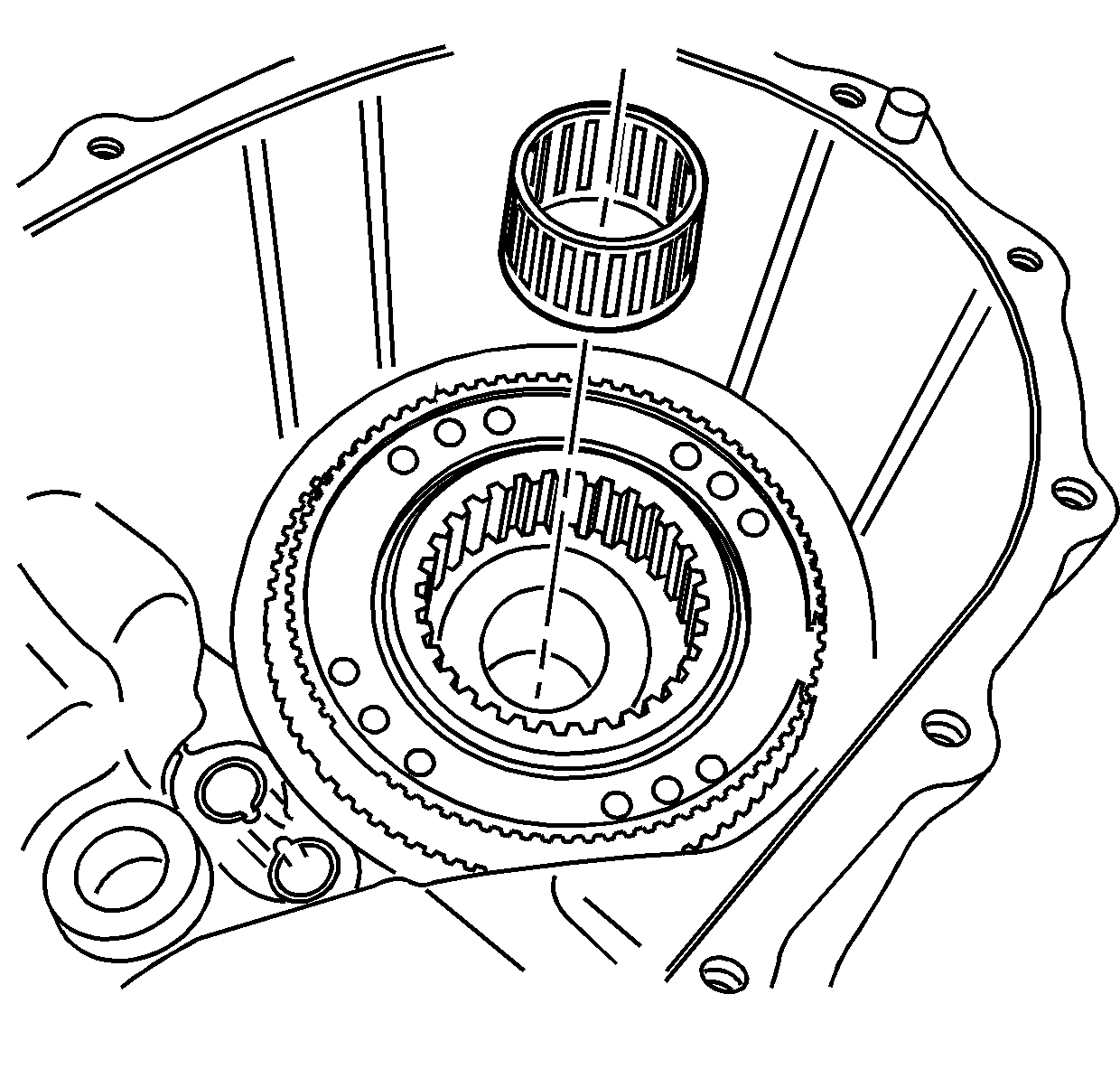
- Remove the rear output shaft front support
bearing from inside of the input shaft.
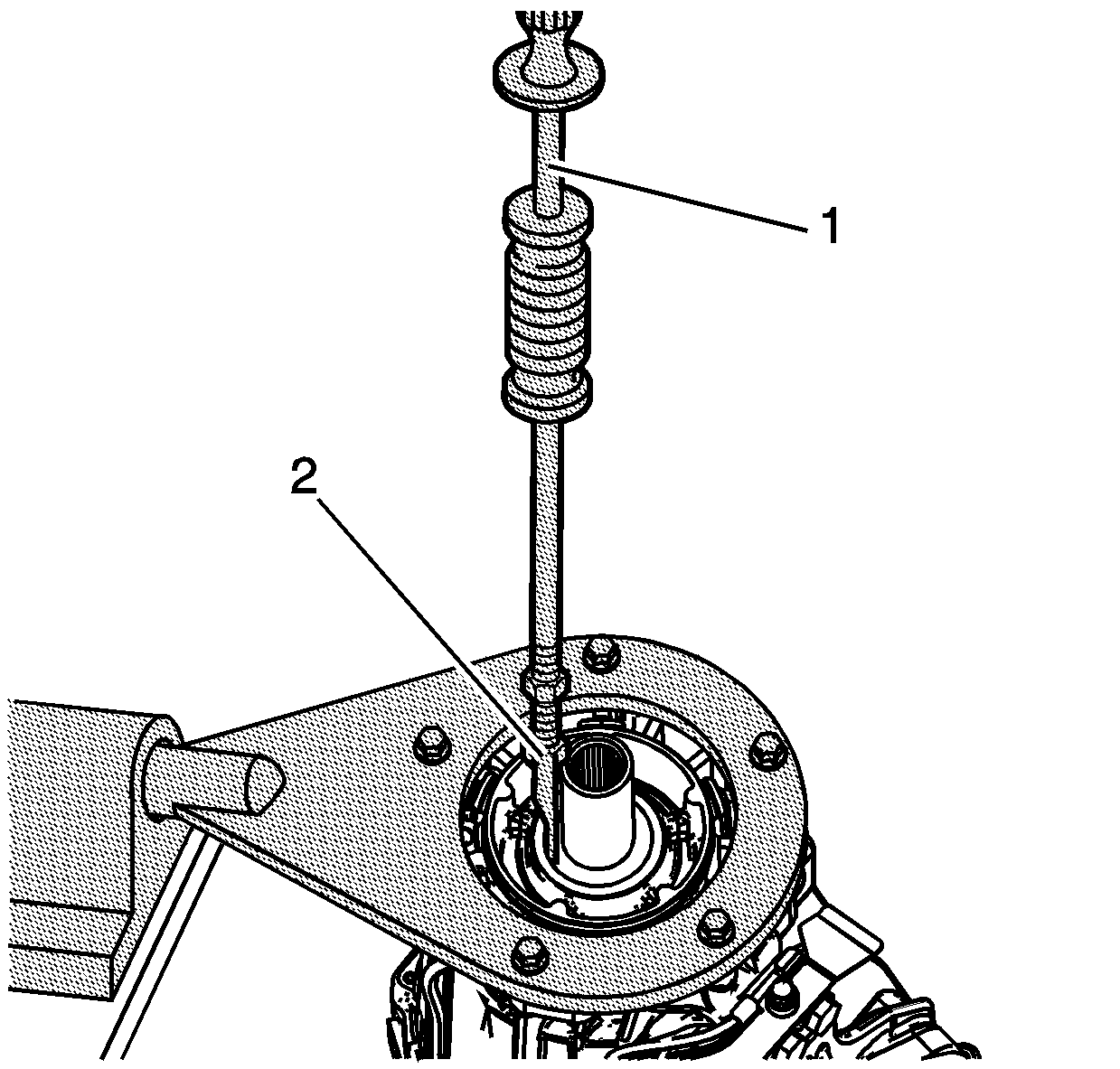
- Using the J 23907
(1) and the J 45278
(2), remove the input shaft seal.
| • | There is not a shoulder to prevent the seal from going into the case. |
| • | Turn, and hold the J 45278
(2) under the seal for removal. |
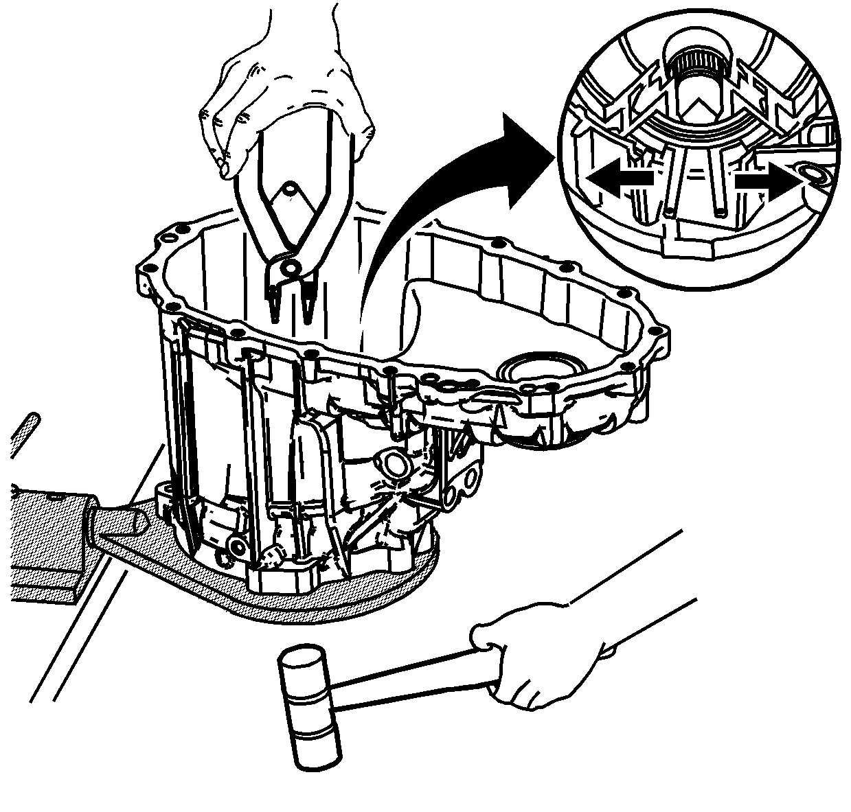
- Using a large pair of snap ring pliers,
spread the retaining ring for the planetary carrier bearing.
Important: Ensure the snap ring pliers do not catch
on the ribs in the case. The retaining ring must be completely spread open.
- While the retaining ring is spread, use a soft face hammer on the input shaft
to remove the planetary carrier assembly.
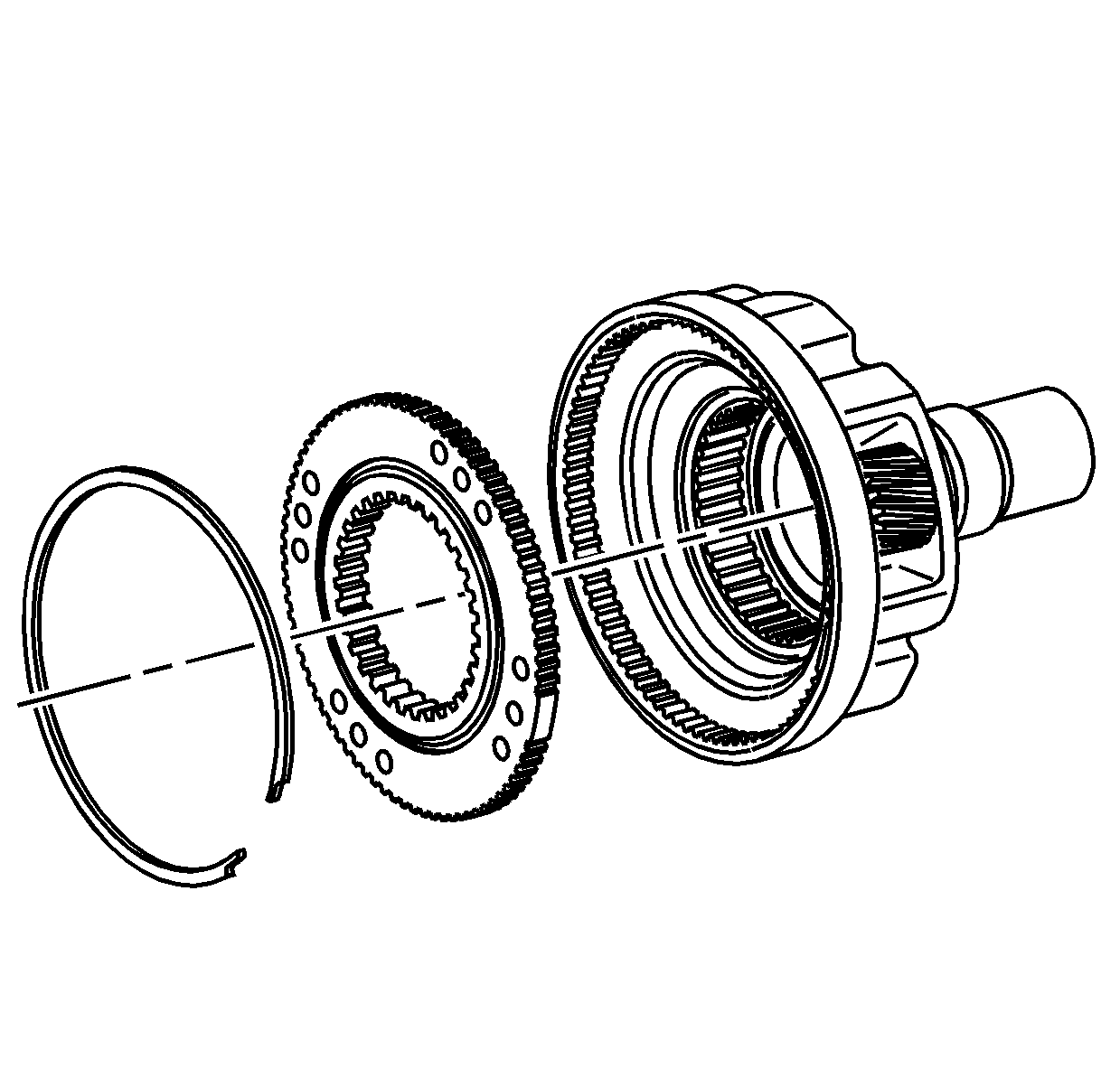
- For assembly purposes, mark the relationship
of the planetary carrier low gear to the planetary carrier.
- Remove the retaining ring for the planetary carrier low gear.
- Remove the planetary carrier low gear.
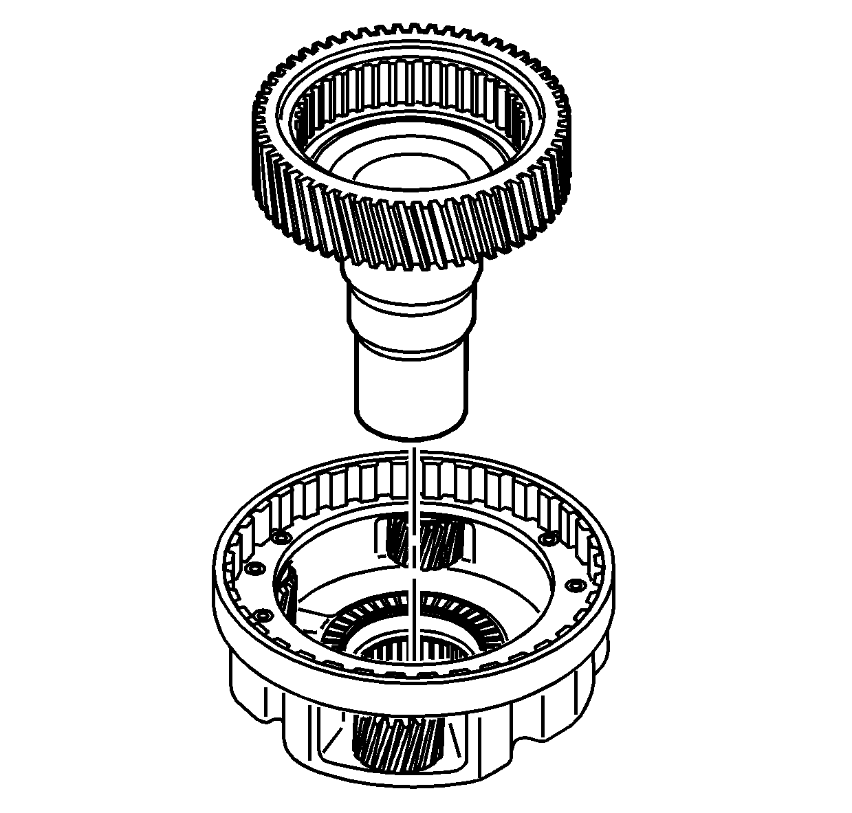
- Remove the input shaft from the planetary
carrier assembly.
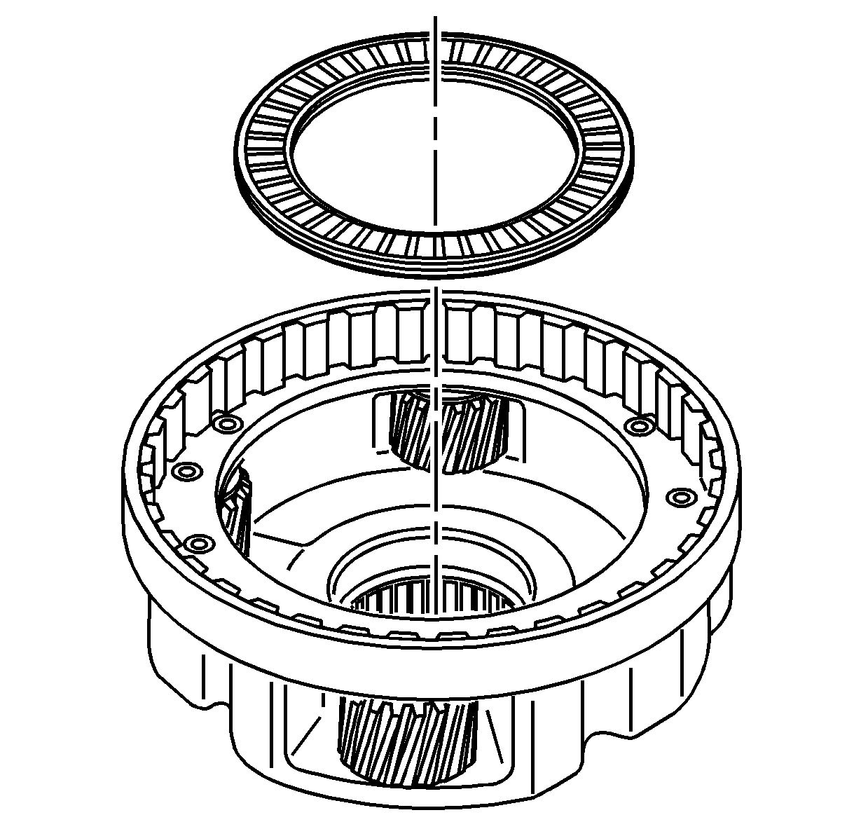
- Remove the input shaft thrust bearing.
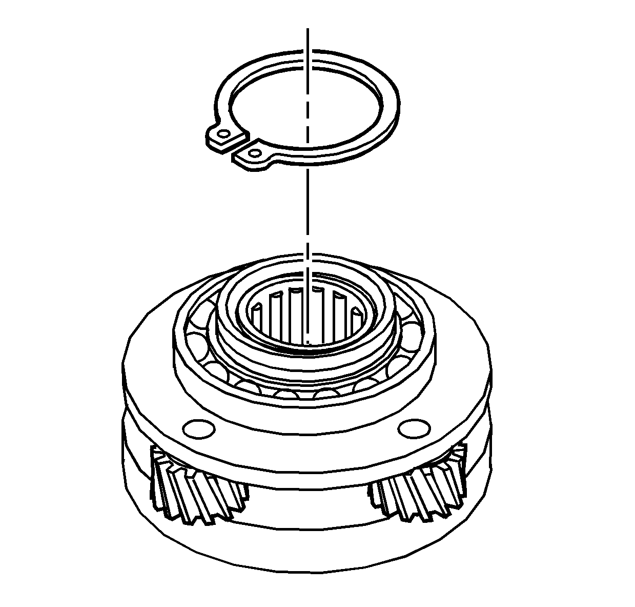
- Remove the planetary carrier assembly bearing
retaining ring.
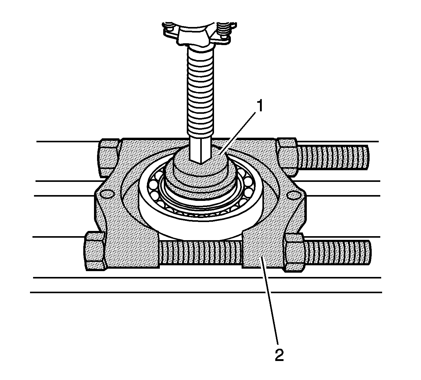
- Using a hydraulic press with the J 45933-1 (1)
of the J 45933
and the J 22912-B
(2), remove the
planetary carrier bearing.
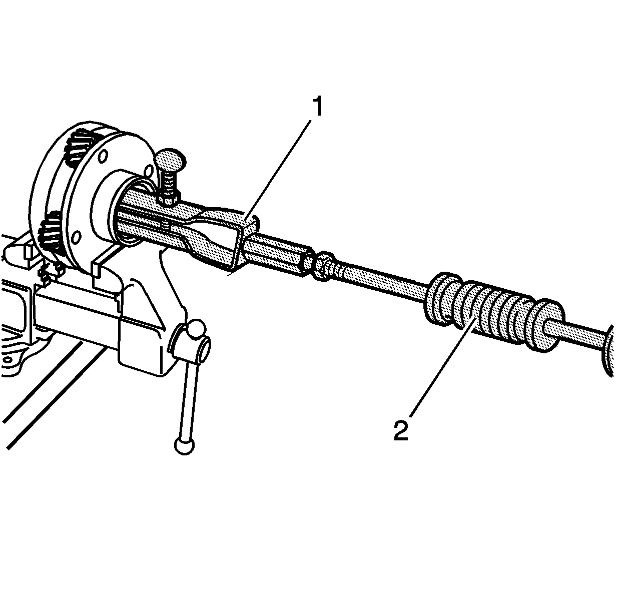
- Using the J 26941
(1) and the J 23907
(2), remove the input shaft bearing from the planetary carrier.
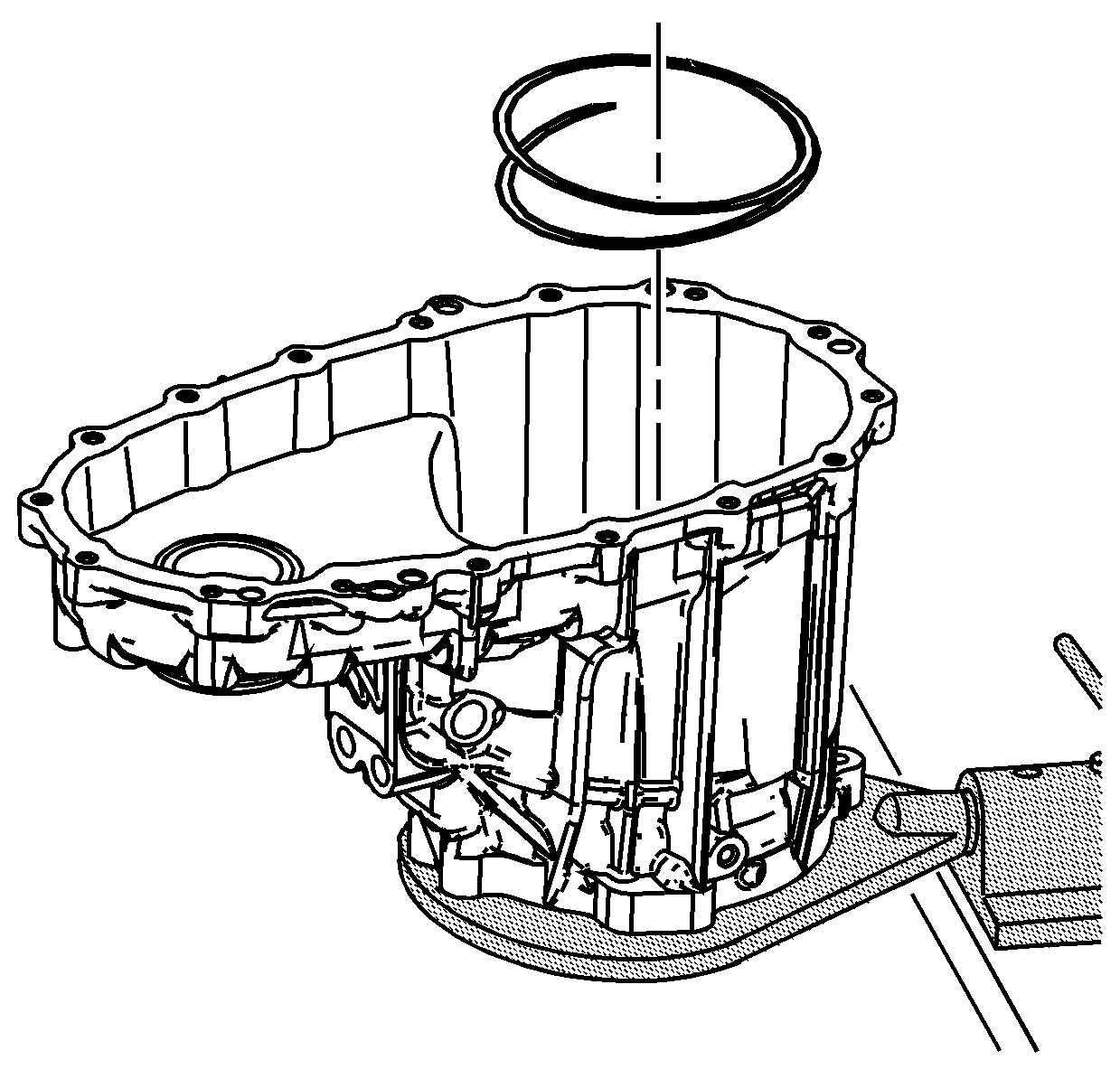
- Remove the annulus gear spiral retaining
ring.
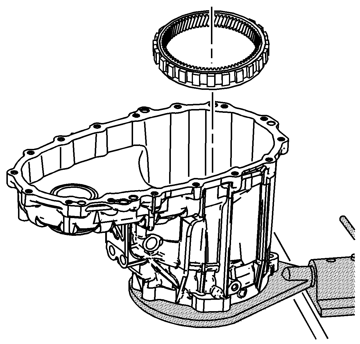
- Remove the annulus gear.
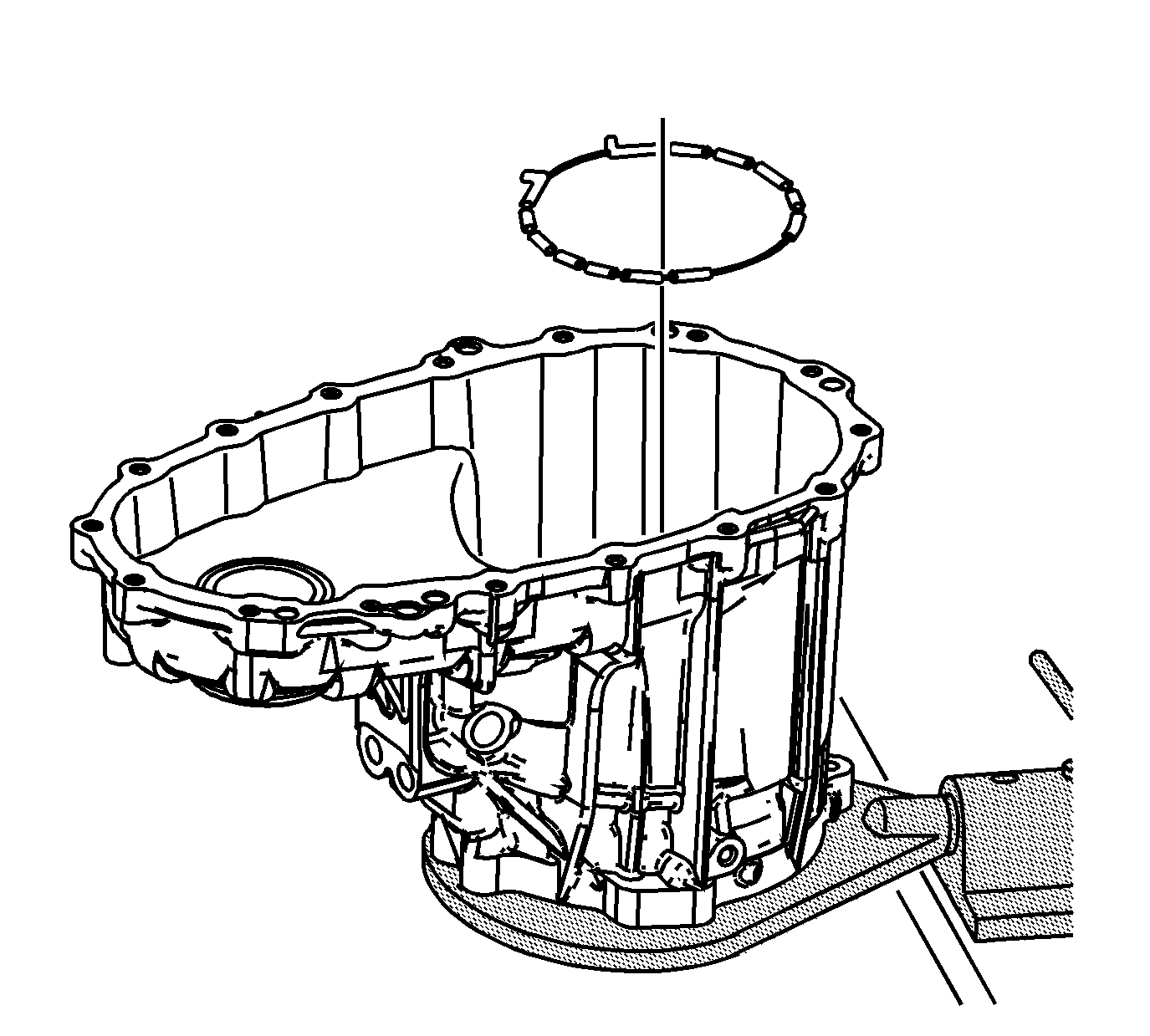
- Remove the annulus gear damper.
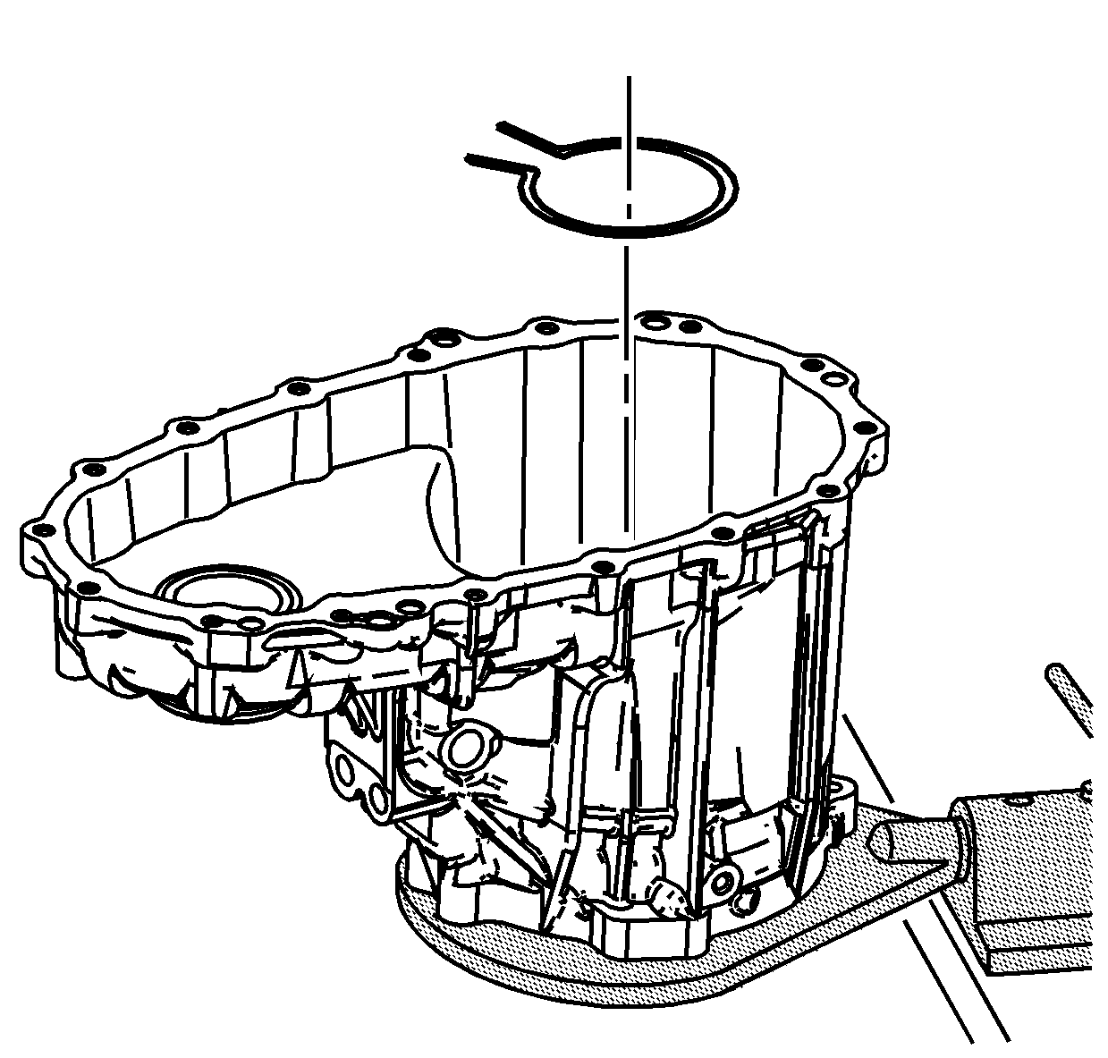
- Remove the carrier bearing outer retaining
ring from the front case.
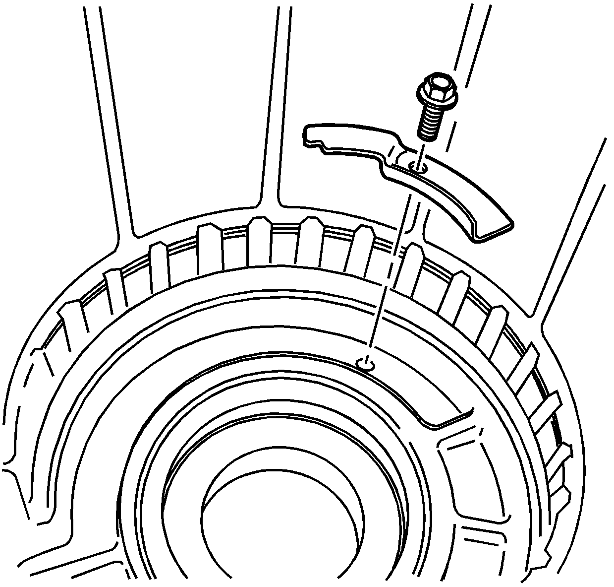
- If necessary, remove the breather baffle
and bolt.
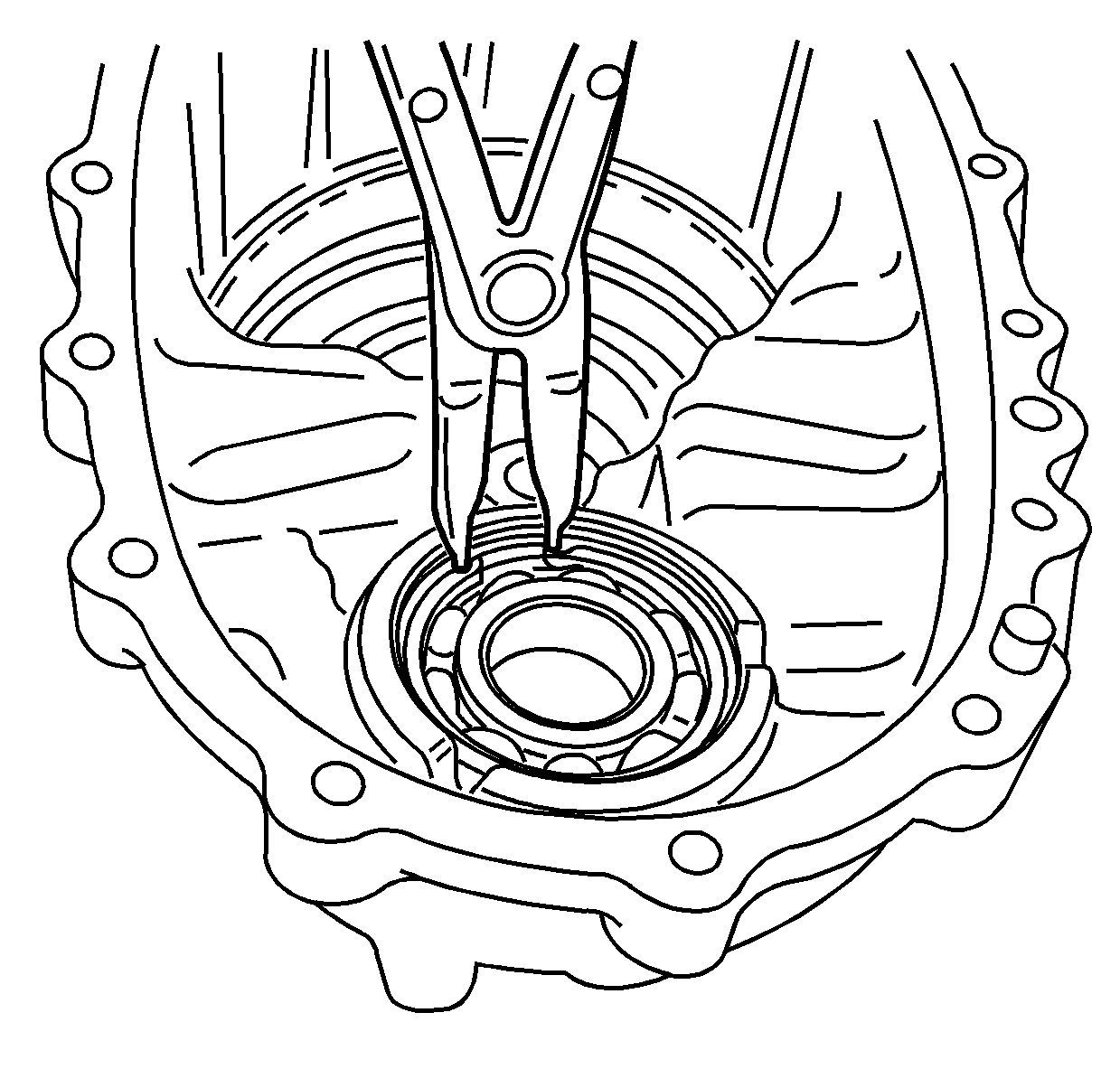
- Remove the front output shaft front bearing
retaining ring.
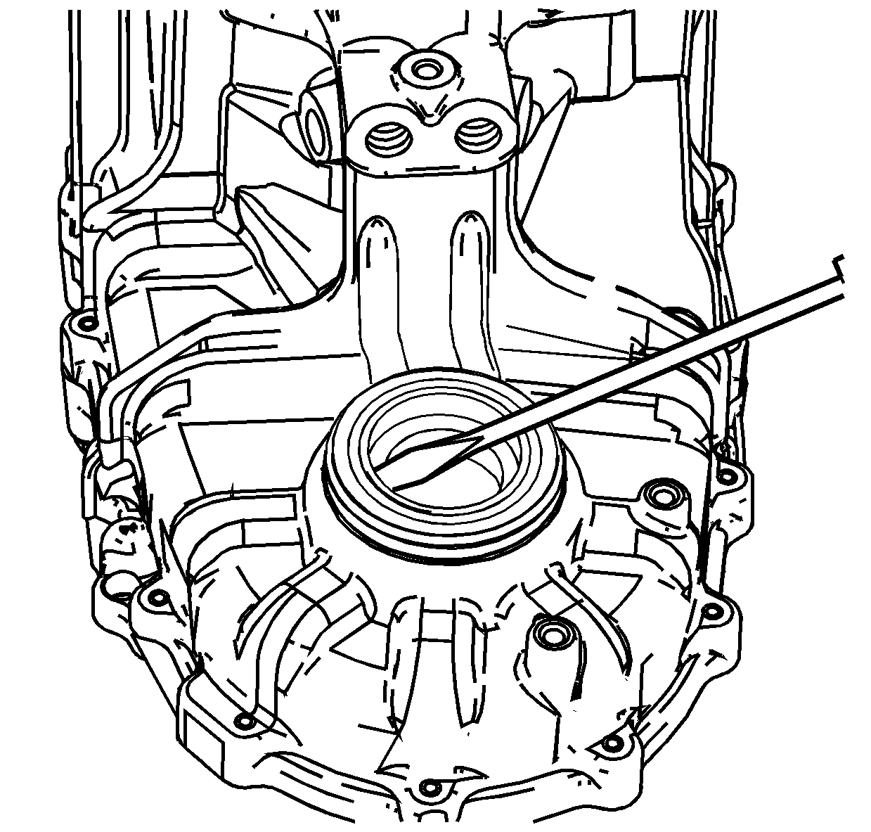
- Remove the front output shaft seal.
- Remove the front case half from the J 45759
.
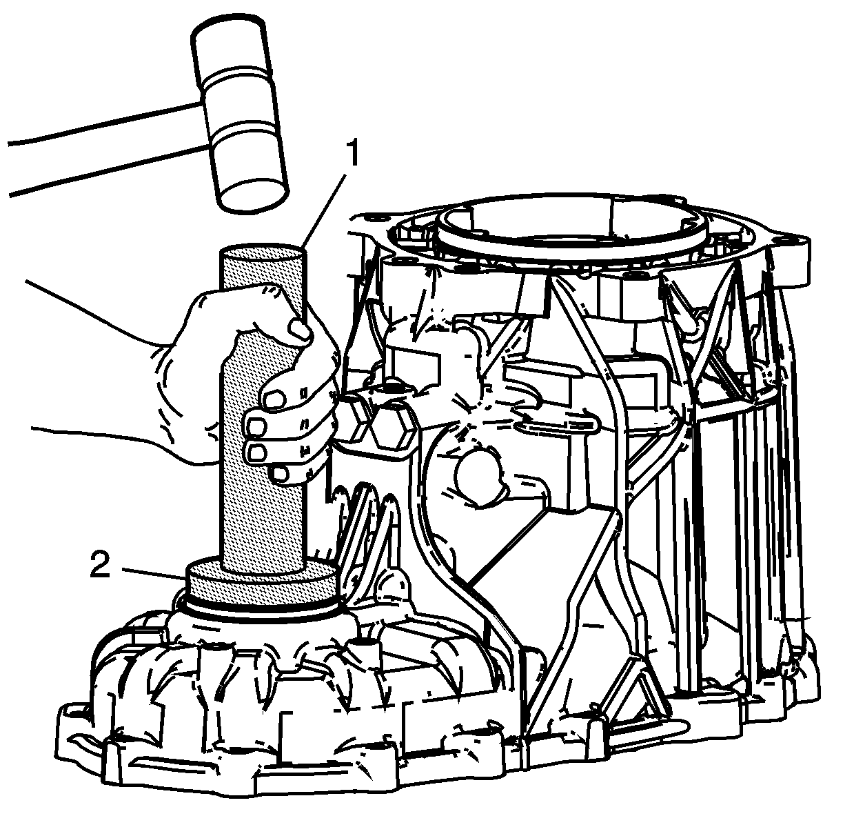
- Inspect the front output shaft bearing for
being faulty. Refer to
Transfer Case Cleaning and Inspection
.
- Using the J 8092
(1)
and the J 46199
(2),
remove the front output shaft front bearing.
- Discard the bearing after removal.
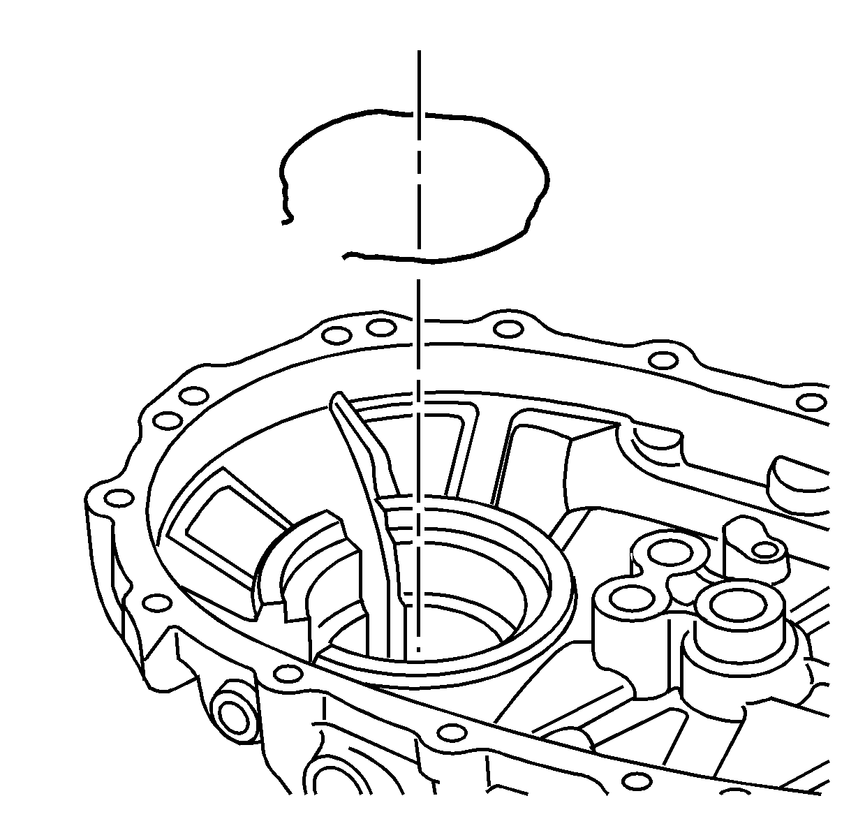
- Remove the oil pump retaining ring from
the rear case half.
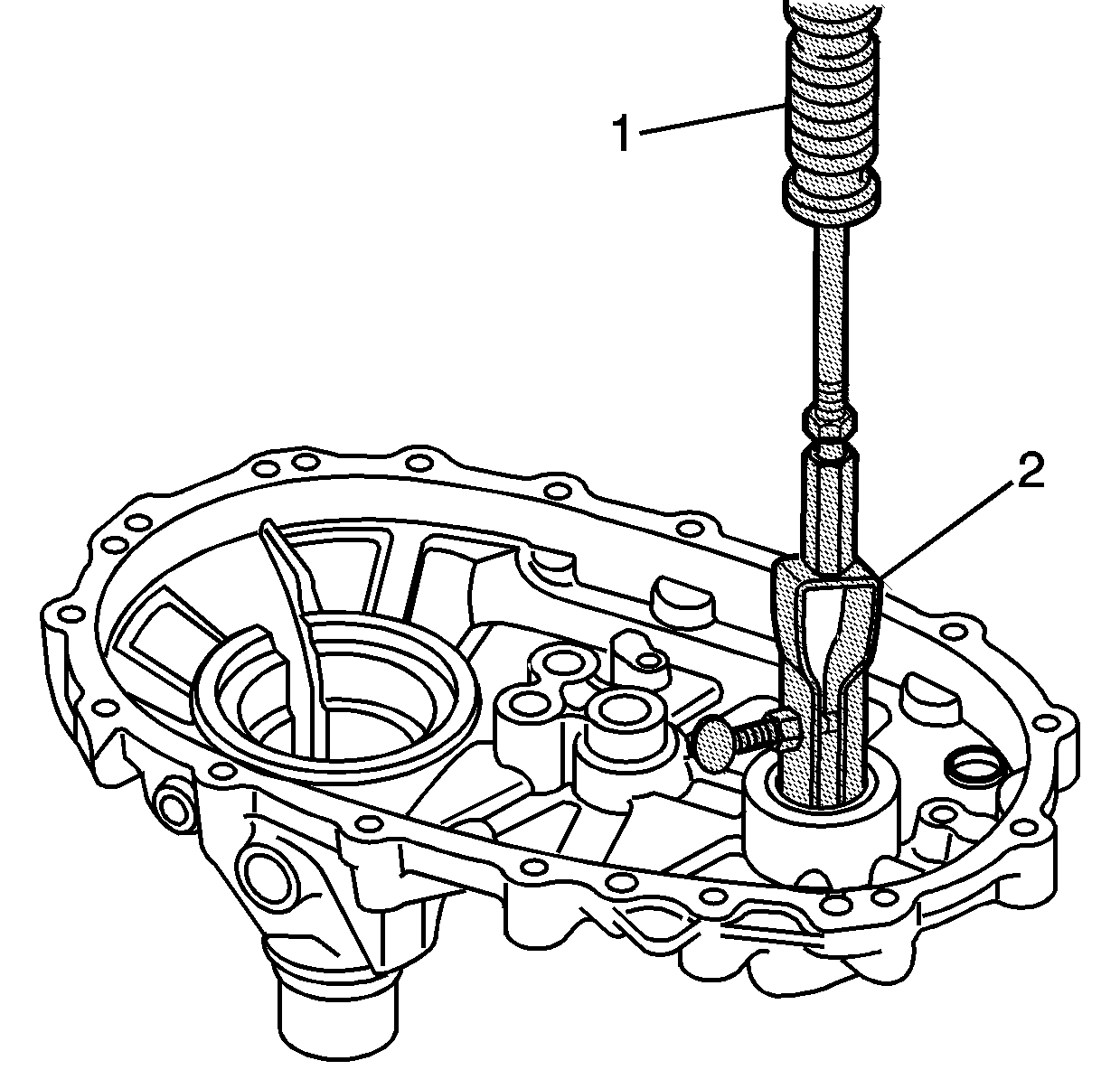
- Using the J 23907
(1) and the J 29369-2
(2), remove the front output shaft rear bearing from the
rear case half. Do not use the bearing after removal.
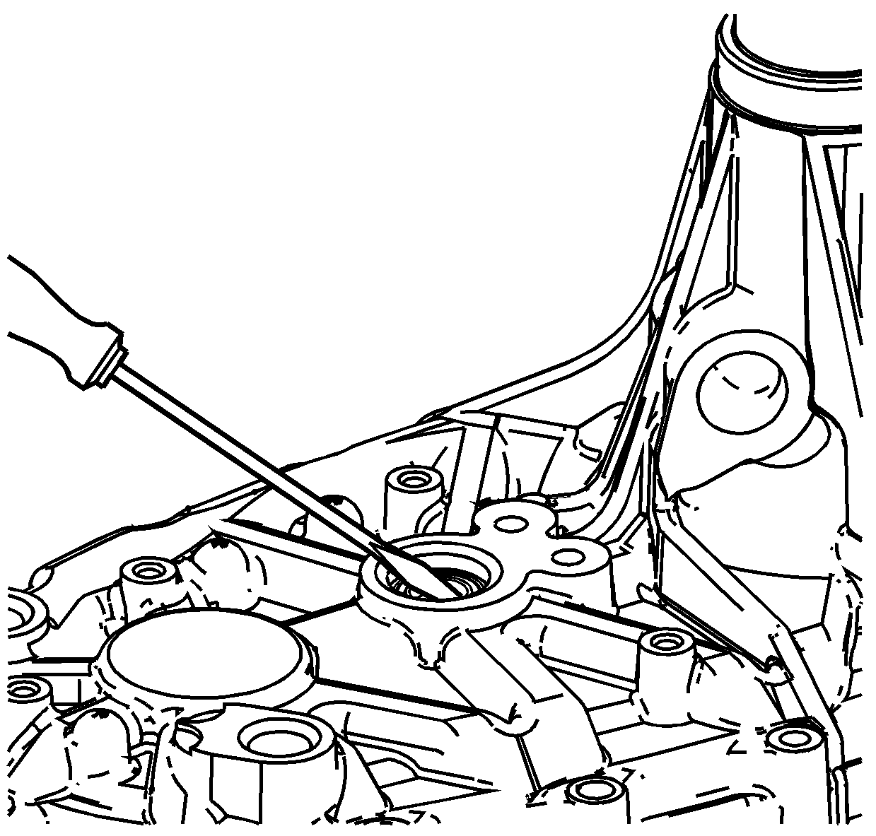
- Remove the control actuator shaft seal from
the rear case.
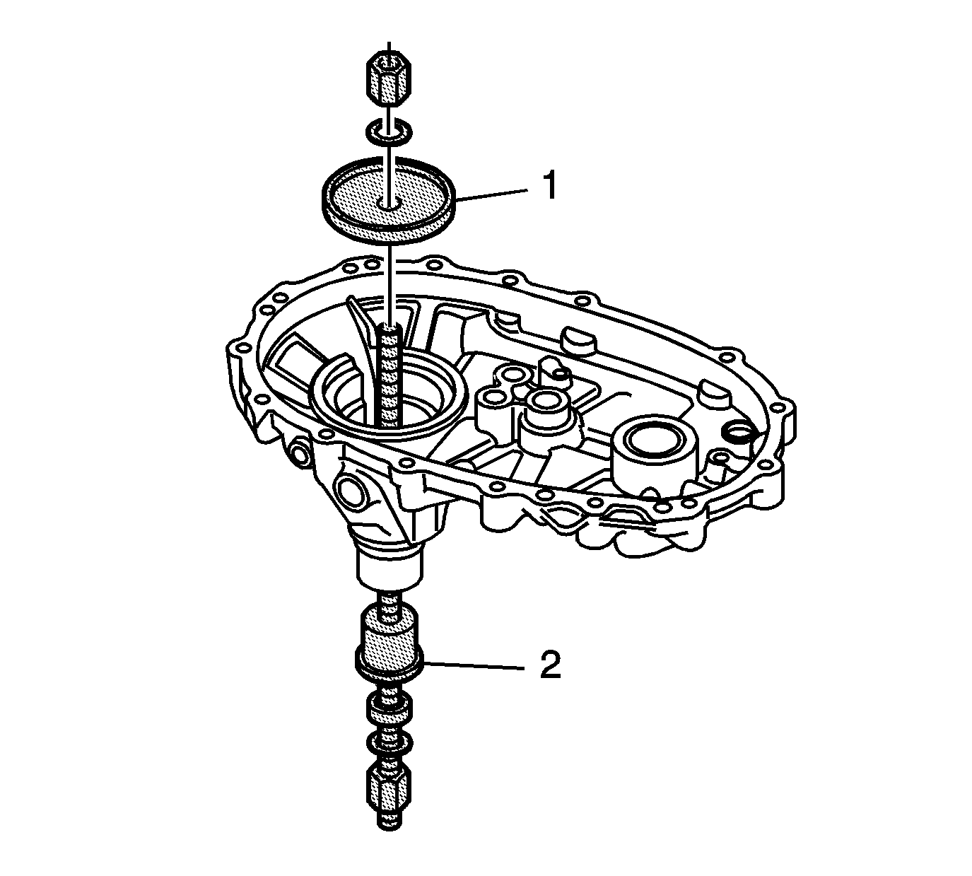
- Inspect the rear bushing for being faulty.
Refer to
Transfer Case Cleaning and Inspection
.
Important:
| • | Use the thrust bearing between the J 45933-4 (2)
and a washer. |
| • | Ensure the threads, of the threaded shaft, on the J 45933
are lubricated with the supplied lubricant. |
- If the rear bushing is faulty, remove the bushing using the J 45933-4 (2)
and the J 45933-3 (1) of the J 45933
.
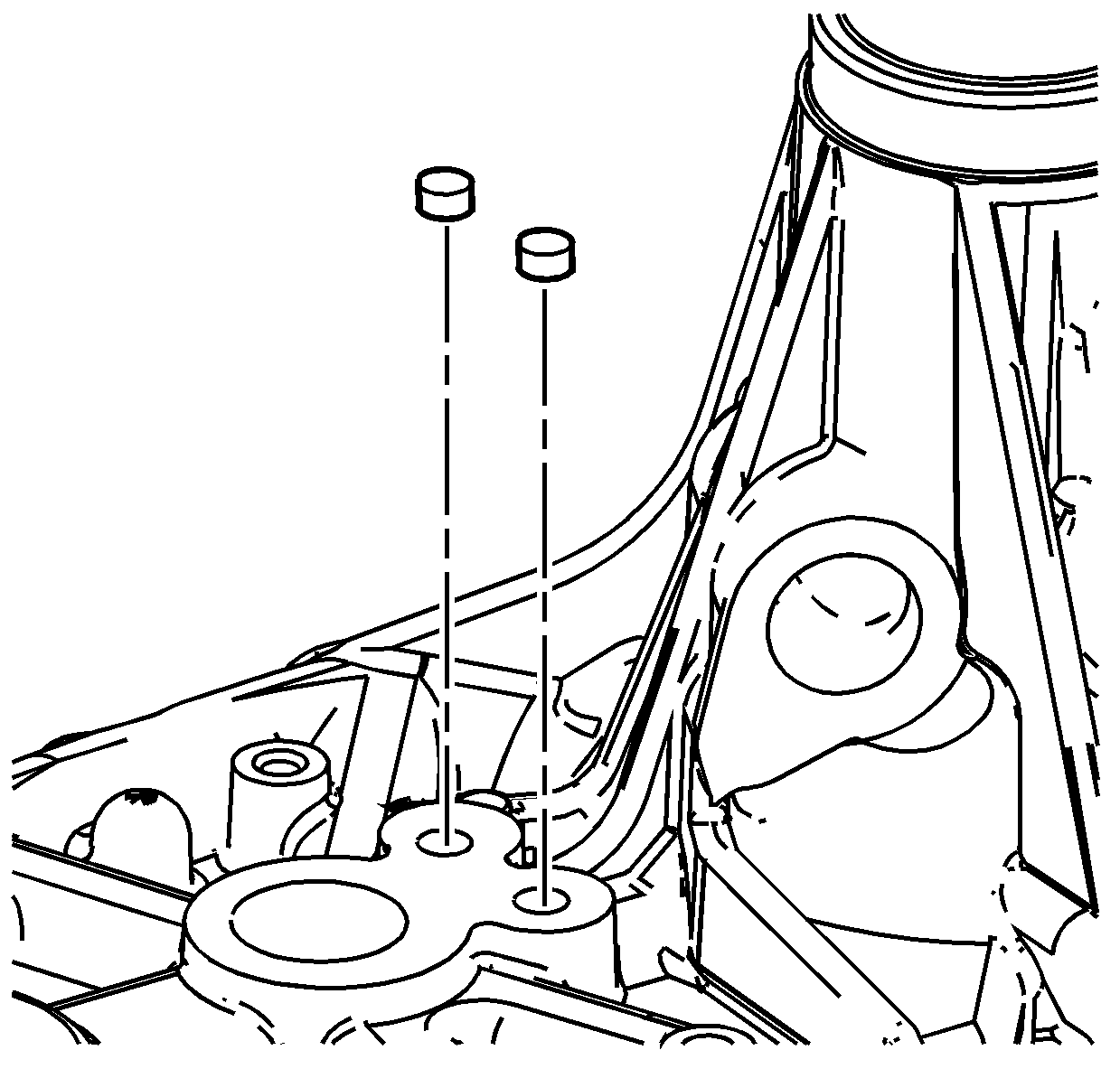
- If necessary, remove the shift shaft plugs.
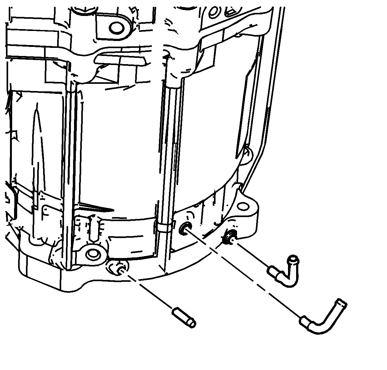
- If necessary, remove the vent or breather
hose pipes.
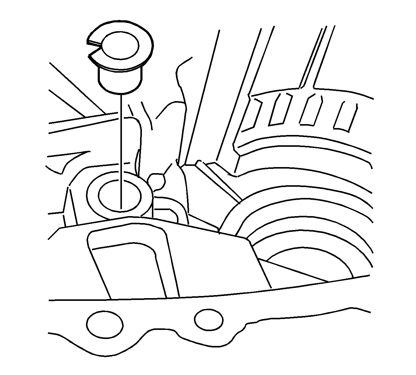
- If necessary, remove the control actuator
shaft bushing.
Important: Only disassemble the shift forks if components
require replacement. Refer to
Transfer Case Cleaning and Inspection
.
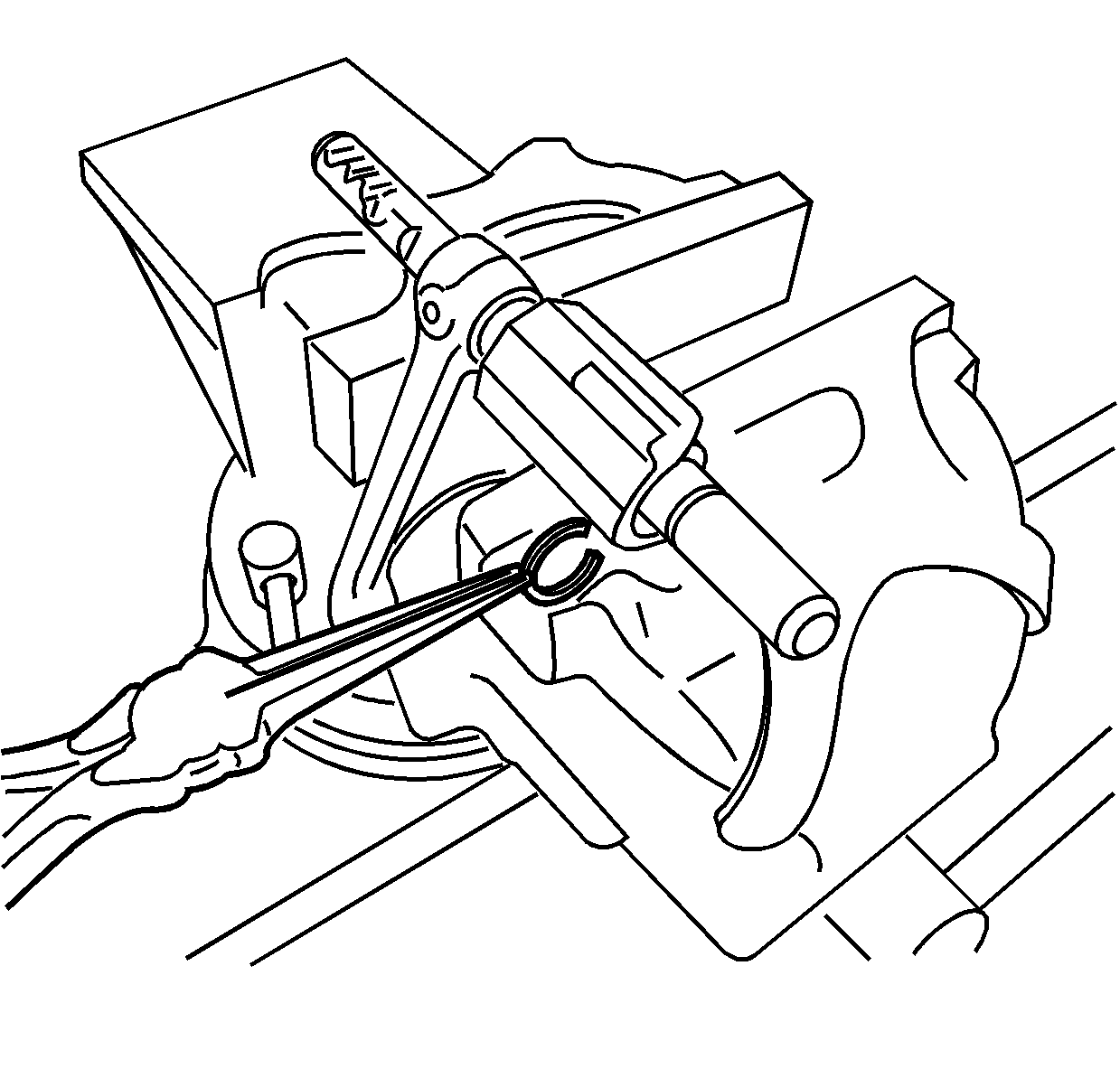
- Disassemble the high/low shift fork by compressing the spring in a vise.
- Remove the retaining ring from the shift shaft.
- Remove the shift fork assembly from the vise and remove the shift block.
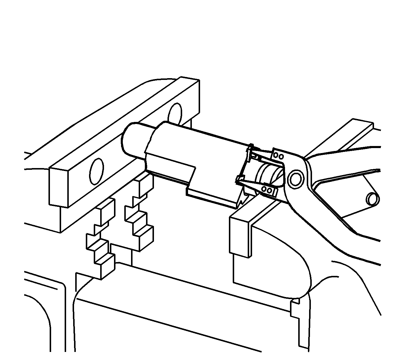
- Using a socket and vise, compress the spring
in the high/low shift block. Use a small enough diameter socket to allow removal
of the inner retaining ring.
- Remove the inner retaining ring from the shift block.
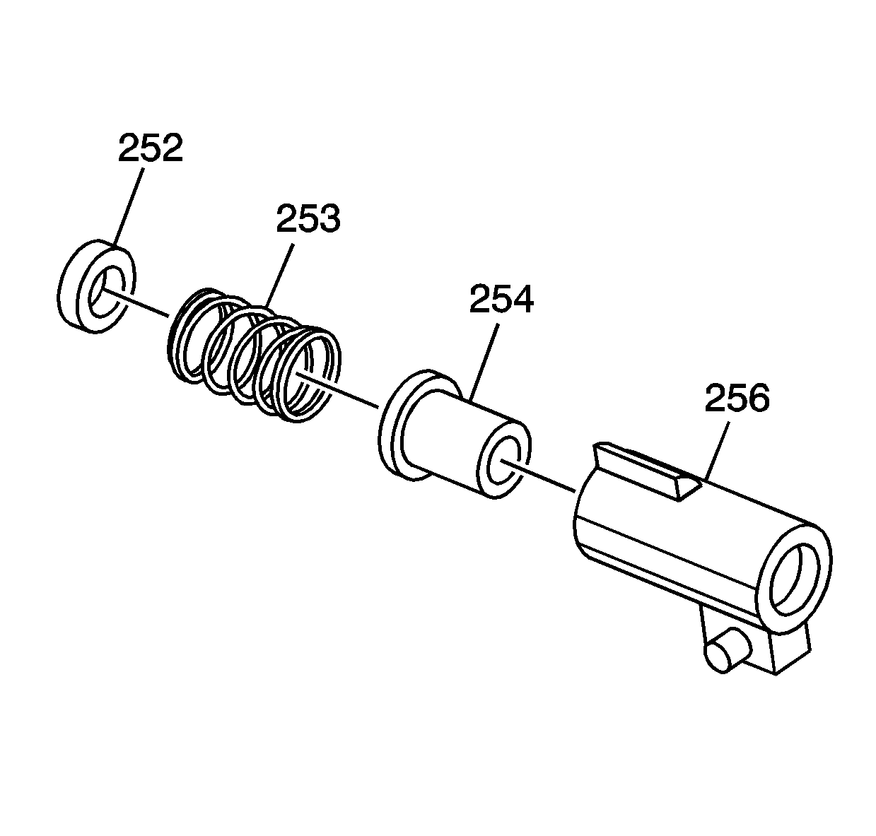
- Remove the shift block from the vise.
- Remove the spring seat (252), the spring (253) and the block
collar (254) from the shift block (256).
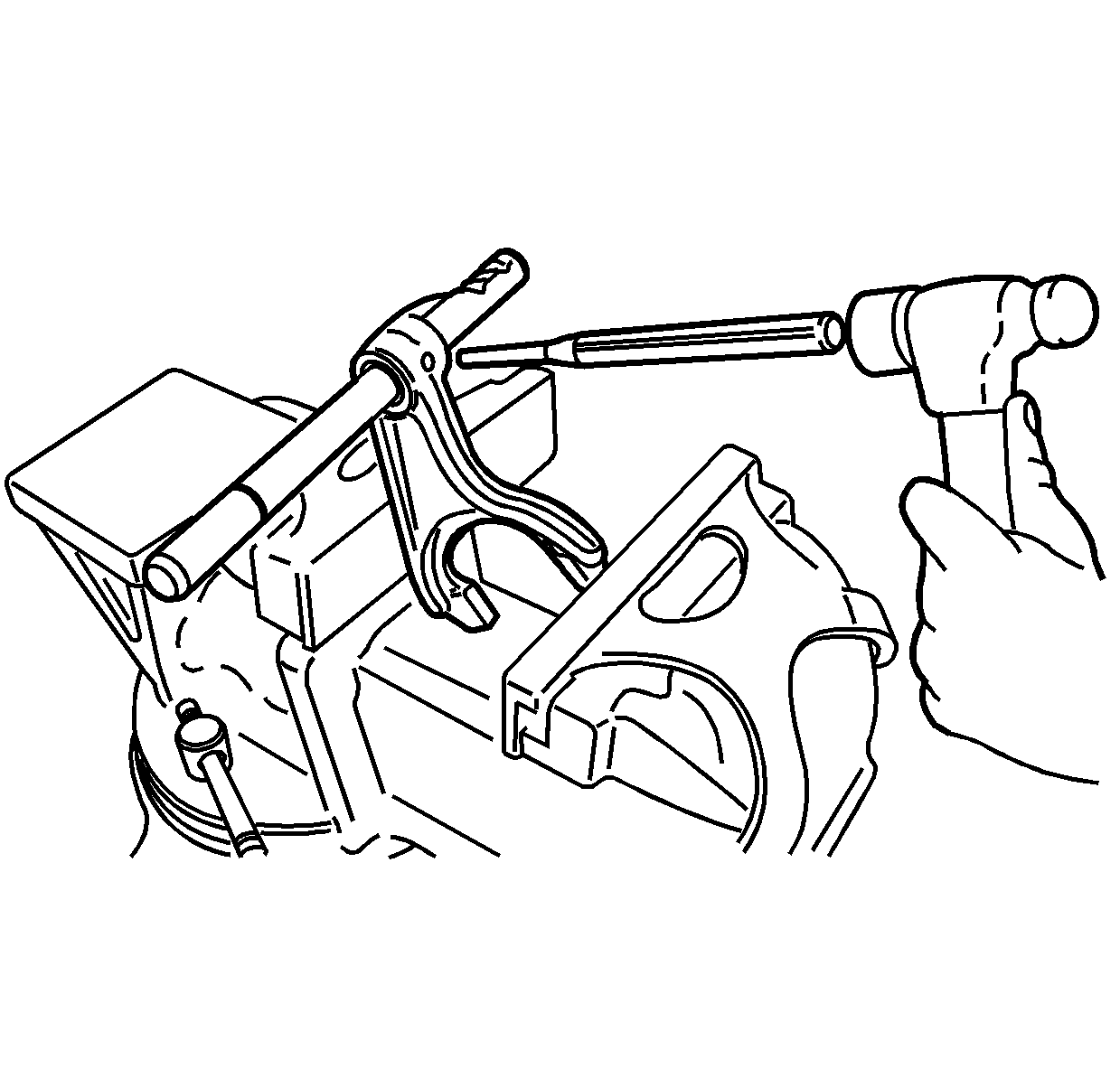
- Remove the roll pin from the high/low shift
fork.
- Remove the shift fork from the shift shaft.
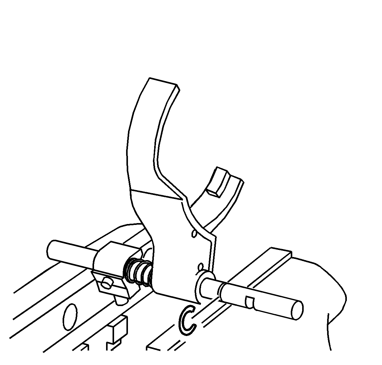
- Disassemble the 2/4 shift fork by compressing
the spring in a vise.
- Remove the retaining ring from the shift shaft.
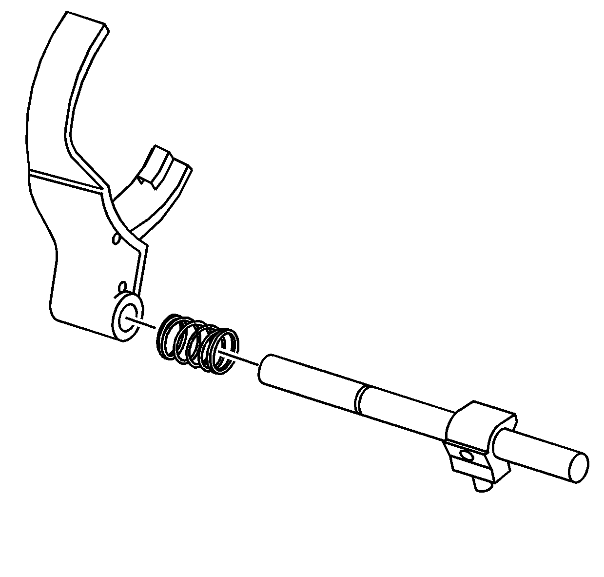
- Remove the 2/4 shift fork and spring from
the shift shaft. The shift block is serviced with the shift shaft.


