General Description
The Aisin AR5 is a 5 speed transmission with 5th gear being an overdrive ratio. All gear positions are synchronized. There are two versions of the AR5, RWD and 4WD. The operation is the same for both transmissions. The differences are the RWD has a longer extension housing and output shaft. In addition, the RWD has a speed reluctor wheel on the output shaft for the vehicle speed sensor. The transmission uses 4 aluminum housings. The clutch housing is removable. Roller ball bearings support the input shaft, countershaft, and output shaft. No shimming is required. For proper set up, select thickness retaining rings are used. All of the speed gears use needle bearings. The AR5 uses a special 75W-90 transmission fluid. Lubrication to the input and output shafts are by splash. An oil receiver at the rear of the countershaft lubricates the 5th gear synchronizer and bearing. On the RWD transmission, an oil trough delivers transmission fluid to the rear bushing.
Shifting Operation
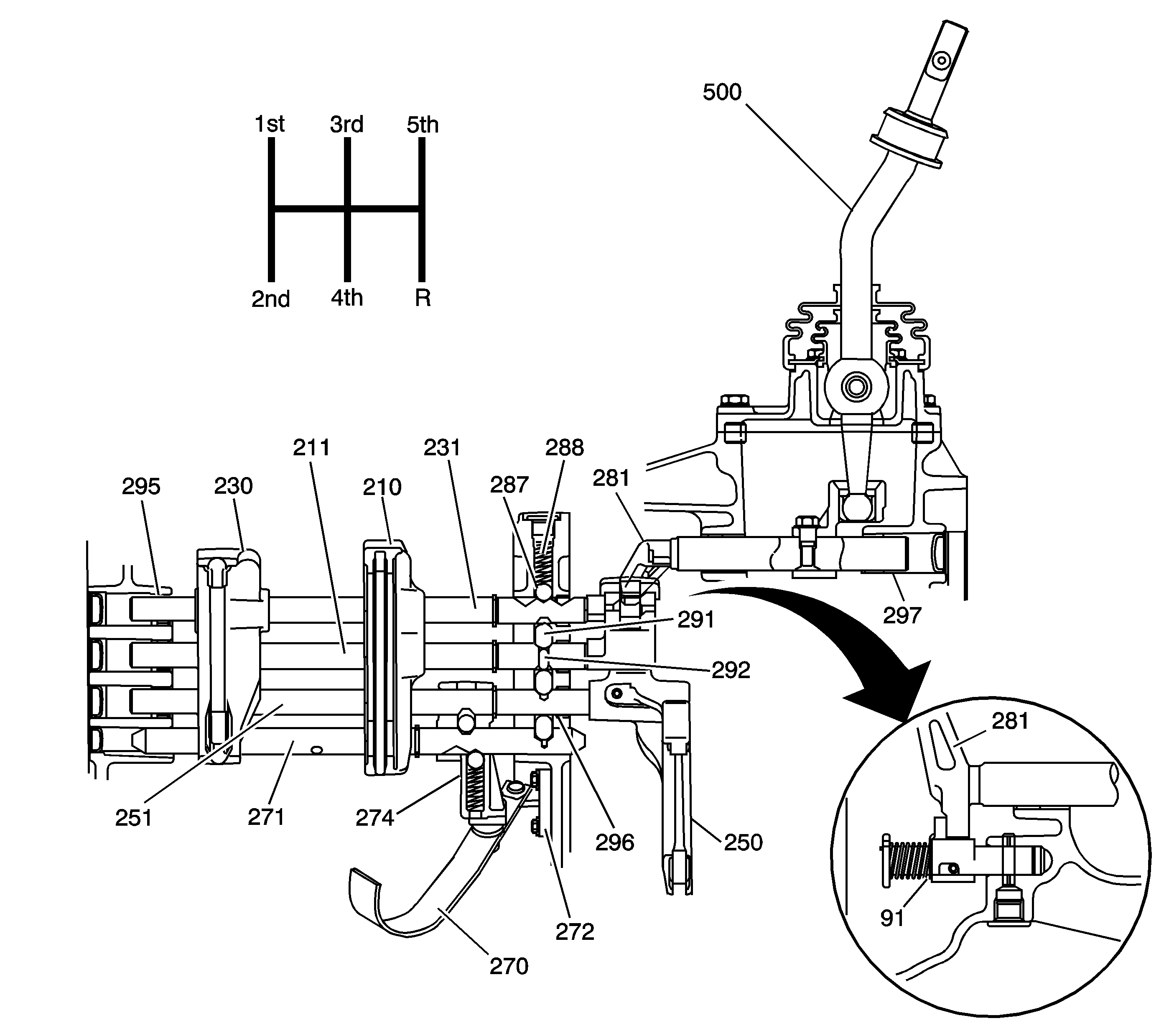
The AR5 has a unique shift system. A single shift control shaft (281) operates four shift shafts. The shift control lever (500) fits into a socket on the shift control shaft (281). Positioning the lever, or finger of the shift control shaft (281), in the gates of the shift shafts, operates the 1st/2nd shift shaft (211), the 3rd/4th shift shaft (231) and the 5th shift shaft (251). Moving the shift control lever (500) side-to-side allows the lever on the shift control shaft (281) to engage into one of the three gates. Moving the shift control lever (500) forward and reverse selects either position of the particular shift shaft. The 3rd/4th shift shaft (231) is the top shift shaft. A bolt holds the 3rd/4th shift fork (230) in place on the shift shaft. When shifted in position, a detent ball (287) and spring (288) located in the top of the intermediate case, holds the shift shaft. The 1st/2nd shift shaft (211) is the second shaft from the top. A bolt holds the 1st/2nd shift fork (210) in place on the shift shaft. In addition, the 1st/2nd shift fork (210) slides on the 3rd/4th shift shaft (231). Using two shift shafts for the shift fork, keeps the shift fork square to the synchronizer sleeve. A small shift shaft interlock pin (292) in the 1st/2nd shift shaft (211) prevents the other shafts from moving. Interlock pins (291), located in the intermediate case on either side of the 1st/2nd shift shaft (231), contact the small interlock pin (292) and lock into a notch on the shift shafts, preventing multiple shift shaft movement. The 5th shift shaft (251) is located third from the top. A roll pin holds the 5th shift fork (250) in place on the shift shaft. In addition, on the 5th shift shaft (251) is the reverse shift lever (274). The reverse shift shaft (271) is the bottom shift shaft. The shift shaft does not move. An interlock pin, in the intermediate case, holds the shaft in place. Instead, the shift shaft has detents for the detent ball and spring located in the reverse shift lever (274). When moving the 5th shift shaft (251) forward, the retaining clip at the rear of the reverse shift lever (274) moves the reverse shift lever (274). The reverse shift fork (270) swivels on the reverse shift lever (274). The reverse shift fork (270) pivots on the reverse shift fork bracket (272) in order to increase the movement of the reverse shift fork (270). To help prevent a mis-shift to the reverse position, a reverse restrictor (91) is located in the extension housing. When going into reverse, a finger on the shift control shaft (281) contacts the plunger on the reverse restrictor (91). Compressing the spring gives the driver a restricted feel when shifting to reverse. Detent balls and springs hold the 1st/2nd shift shaft (211) and the 5th shift shaft (251) in the shift positions. On the right side of the intermediate case are the detent plugs for accessing the detent balls and springs. Even though there is a detent plug for the reverse shift shaft (271), no detent spring and ball is located there. To aid in easy shift operation, the front case shift shaft bushings (295) and the intermediate case shift shaft bushings (296) support the 1st/2nd shift shaft (211), the 3rd/4th shift shaft (231), and the 5th shift shaft (251). Supporting the shift control shaft (281) at each end are the extension housing shift shaft bushings (297).
Power Flow - Forward Gears
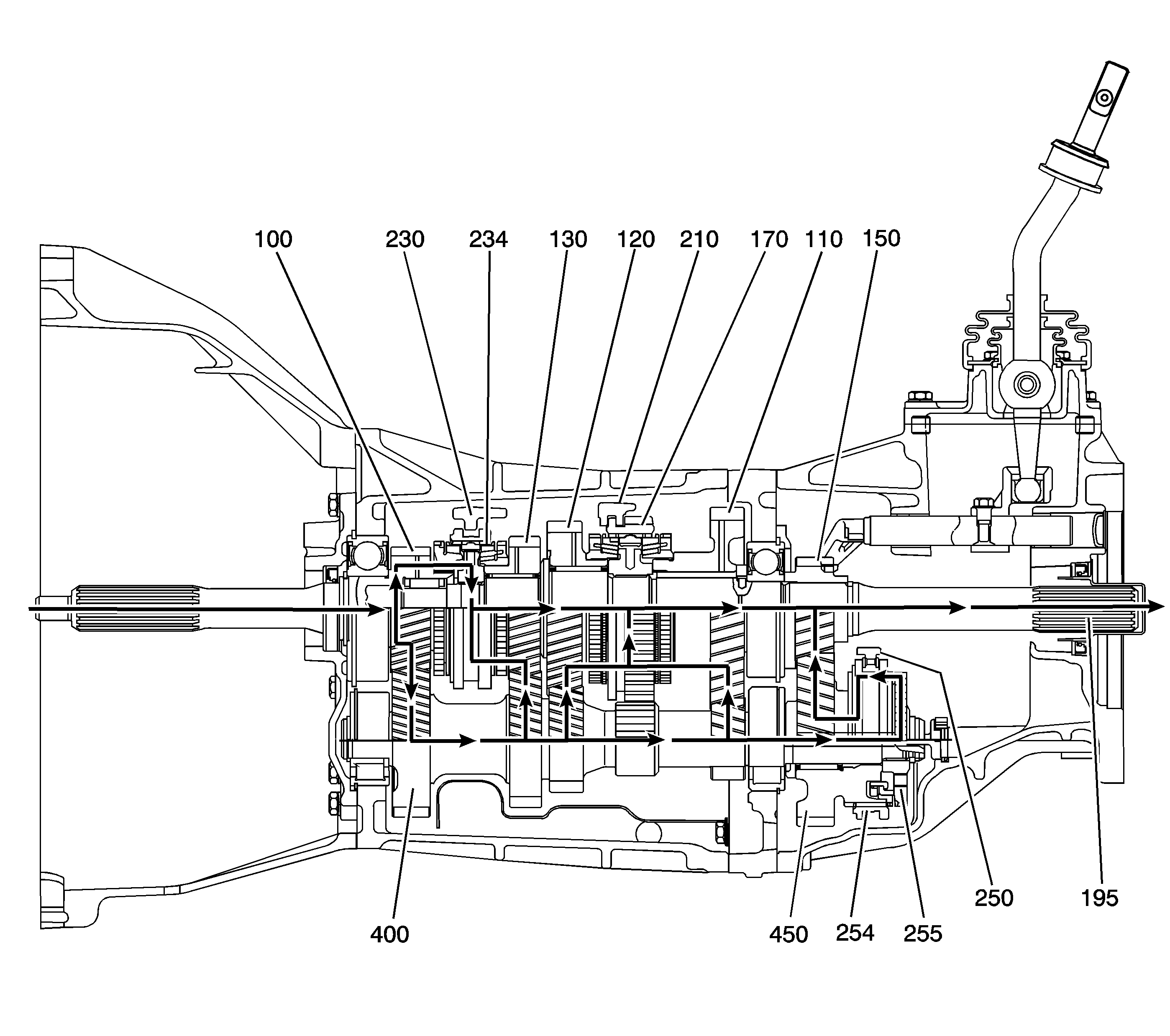
The power flow through the AR5 transmission speed gears is a basic transmission design. During 1st gear (110), 2nd gear (120) or 3rd gear (130), the input shaft (100) delivers the power from the engine to the transmission. The external teeth on the input shaft (100) engage with the front gear on the counter shaft (400). Depending on the selected gear position, the power flows from a countershaft gear to a speed gear and then through the speed gear selector teeth. The gear selector teeth engage with the synchronizer sleeve. The synchronizer sleeve is slip splined on the synchronizer hub. The synchronizer hubs are press fit on the output shaft, therefore delivering the engine power to the output shaft (195).
1st gear: Moving the 1st/2nd shift fork (210) rearward, moves the 1st/2nd synchronizer sleeve (170). The inner teeth on the synchronizer sleeve push against the blocking ring teeth, causing the synchronizer rings to contact, and the speed gear and the output shaft to match speeds. The synchronizer sleeve (170) then engages the selector teeth on 1st gear (110). Power flow is now from the input shaft (100) to the countershaft (400) to the 1st gear (110), through the synchronizer and to the output shaft (195).2nd gear: Moving the 1st/2nd shift fork (210) forward, moves the 1st/2nd synchronizer sleeve (170). The inner teeth on the synchronizer sleeve push against the blocking ring teeth, causing the synchronizer rings to contact, and the speed gear and the output shaft to match speeds. The synchronizer sleeve (170) then engages the selector teeth on 2nd gear (120). Power flow is now from the input shaft (100) to the countershaft (400) to the 2nd gear (120) through the synchronizer and to the output shaft (195).
3rd gear: Moving the 3rd/4th shift fork (230) rearward, moves the 3rd/4th synchronizer sleeve (234). The inner teeth on the synchronizer sleeve push against the blocking ring teeth, causing the synchronizer rings to contact, and the speed gear and the output shaft to match speeds. The synchronizer sleeve (234) then engages the selector teeth on 3rd gear (130). Power flow is now from the input gear (100) to the countershaft (400) to the 3rd gear (130) through the synchronizer and to the output shaft (195).
4th gear: In 4th gear, the power flow goes directly from the input shaft (100) to the output shaft (195) through the 3rd/4th synchronizer. This happens because 4th gear is the same ratio as the engine speed. When moving the 3rd/4th shift fork (230), the 3rd/4th synchronizer sleeve (234) inner teeth push against the single blocking ring teeth for 4th gear. Matching the input shaft (100) to the output shaft (195) allows the synchronizer sleeve to engage to the selector teeth on the input shaft (100).
5th gear: 5th gear is an overdrive ratio. Because 5th gear is overdrive, the 5th gear (150) is splined on the rear of the output shaft (195). The 5th countershaft gear (450) is located on the rear of the countershaft (400) and rotates on needle bearings. The 5th countershaft gear (450) is larger diameter, with more teeth than 5th gear (150). The power flow for 5th gear is from the input shaft (100) to the countershaft (400). Moving the 5th shift fork (250) rearward, the 5th/reverse synchronizer sleeve (254) pushes against the teeth on the blocking ring, forcing the blocking ring against the middle ring. The middle ring has tabs in the 5th synchronizer gear (255). The blocking rings match the speed of the 5th synchronizer gear (255) and the 5th countershaft gear (250), which is rotating by the 5th gear (150). Matching the speeds, the synchronizer sleeve slides onto the 5th synchronizer gear. Power flows from the countershaft (400) to the 5th synchronizer gear (255), through the synchronizer sleeve. With the synchronizer sleeve also engaged with the 5th countershaft gear (450), power flows from the 5th countershaft gear (450) to the 5th gear (150) and to the output shaft (195), which now turns faster than the speed of the input shaft (100).
Power Flow - Reverse Gear
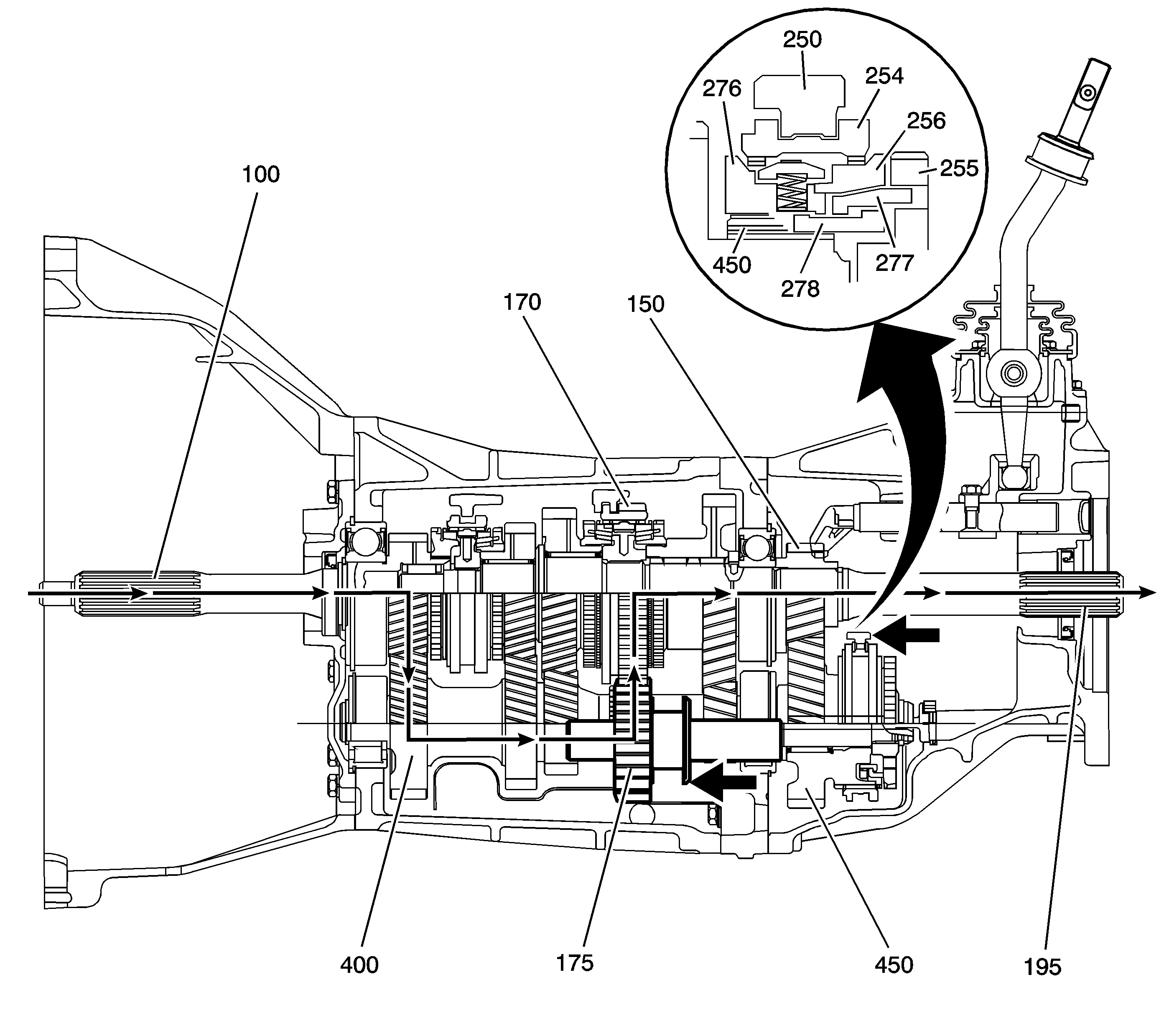
Moving the reverse shift fork forward, slides the reverse idler gear (175) forward on the reverse idler gear shaft. The reverse idler gear (175) engages with the countershaft reverse gear and with the outer or reverse gear teeth on the 1st/2nd synchronizer sleeve (170). The synchronizer sleeve is the reverse gear in this application. The synchronizer sleeve (170) is slip splined on the synchronizer hub. The synchronizer hub is pressed on the output shaft (195). The power flow in reverse is from the input shaft (100), to the countershaft (400), to the reverse idler gear (175), to the reverse gear teeth on the 1st/2nd synchronizer sleeve (170), through the synchronizer and to the output shaft (195). Using the 5th/reverse synchronizer avoids gear clash when shifting in reverse. When moving the reverse shift fork forward, simultaneously the 5th shift fork (250) moves the 5th/reverse synchronizer sleeve (254) forward. The internal splines of the synchronizer sleeve slide on the splines of the 5th countershaft gear (450). At the same time, the synchronizer sleeve splines are pushing against the teeth on the reverse gear synchronizer ring (276). The action moves the reverse gear synchronizer ring (276) forward. The reverse/5th inner ring (278), or pull ring, locking to the reverse gear synchronizer ring (276) moves forward. The reverse/5th inner ring (278) pulls forward, and tabbed lock to the reverse/5th internal ring (277) forces the reverse internal ring (277) against the 5th gear blocking ring (256). The 5th gear blocking ring (256) is moving at the same revolutions as the output shaft (195). The reverse internal ring (277), tabbed to the 5th synchronizer gear (255), is revolving at the countershaft (400) speed. The synchronizer action matches the revolutions of the countershaft (400) to output shaft (195) revolutions, allowing the reverse idler (175) to engage without gear clashing.
General Description
The Aisin AR5 is a 5 speed transmission with 5th gear being an overdrive ratio. All gear positions are synchronized. There are two versions of the AR5, RWD and 4WD. The operation is the same for both transmissions. The differences are the RWD has a longer extension housing and output shaft. In addition, the RWD has a speed reluctor wheel on the output shaft for the vehicle speed sensor. The transmission uses 4 aluminum housings. The clutch housing is removable. Roller ball bearings support the input shaft, countershaft, and output shaft. No shimming is required. For proper set up, select thickness retaining rings are used. All of the speed gears use needle bearings. The AR5 uses a special 75W-90 transmission fluid. Lubrication to the input and output shafts are by splash. An oil receiver at the rear of the countershaft lubricates the 5th gear synchronizer and bearing. On the RWD transmission, an oil trough delivers transmission fluid to the rear bushing.
Shifting Operation
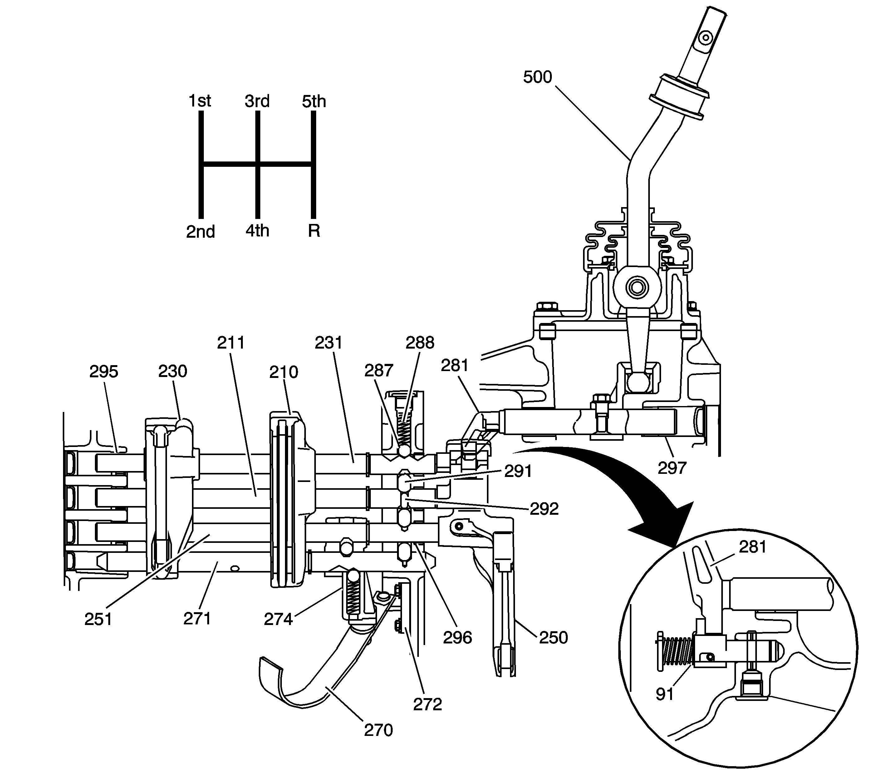
The AR5 has a unique shift system. A single shift control shaft (281) operates four shift shafts. The shift control lever (500) fits into a socket on the shift control shaft (281). Positioning the lever, or finger of the shift control shaft (281), in the gates of the shift shafts, operates the 1st/2nd shift shaft (211), the 3rd/4th shift shaft (231) and the 5th shift shaft (251). Moving the shift control lever (500) side-to-side allows the lever on the shift control shaft (281) to engage into one of the three gates. Moving the shift control lever (500) forward and reverse selects either position of the particular shift shaft. The 3rd/4th shift shaft (231) is the top shift shaft. A bolt holds the 3rd/4th shift fork (230) in place on the shift shaft. When shifted in position, a detent ball (287) and spring (288) located in the top of the intermediate case, holds the shift shaft. The 1st/2nd shift shaft (211) is the second shaft from the top. A bolt holds the 1st/2nd shift fork (210) in place on the shift shaft. In addition, the 1st/2nd shift fork (210) slides on the 3rd/4th shift shaft (231). Using two shift shafts for the shift fork, keeps the shift fork square to the synchronizer sleeve. A small shift shaft interlock pin (292) in the 1st/2nd shift shaft (211) prevents the other shafts from moving. Interlock pins (291), located in the intermediate case on either side of the 1st/2nd shift shaft (231), contact the small interlock pin (292) and lock into a notch on the shift shafts, preventing multiple shift shaft movement. The 5th shift shaft (251) is located third from the top. A roll pin holds the 5th shift fork (250) in place on the shift shaft. In addition, on the 5th shift shaft (251) is the reverse shift lever (274). The reverse shift shaft (271) is the bottom shift shaft. The shift shaft does not move. An interlock pin, in the intermediate case, holds the shaft in place. Instead, the shift shaft has detents for the detent ball and spring located in the reverse shift lever (274). When moving the 5th shift shaft (251) forward, the retaining clip at the rear of the reverse shift lever (274) moves the reverse shift lever (274). The reverse shift fork (270) swivels on the reverse shift lever (274). The reverse shift fork (270) pivots on the reverse shift fork bracket (272) in order to increase the movement of the reverse shift fork (270). To help prevent a mis-shift to the reverse position, a reverse restrictor (91) is located in the extension housing. When going into reverse, a finger on the shift control shaft (281) contacts the plunger on the reverse restrictor (91). Compressing the spring gives the driver a restricted feel when shifting to reverse. Detent balls and springs hold the 1st/2nd shift shaft (211) and the 5th shift shaft (251) in the shift positions. On the right side of the intermediate case are the detent plugs for accessing the detent balls and springs. Even though there is a detent plug for the reverse shift shaft (271), no detent spring and ball is located there. To aid in easy shift operation, the front case shift shaft bushings (295) and the intermediate case shift shaft bushings (296) support the 1st/2nd shift shaft (211), the 3rd/4th shift shaft (231), and the 5th shift shaft (251). Supporting the shift control shaft (281) at each end are the extension housing shift shaft bushings (297).
Power Flow - Forward Gears
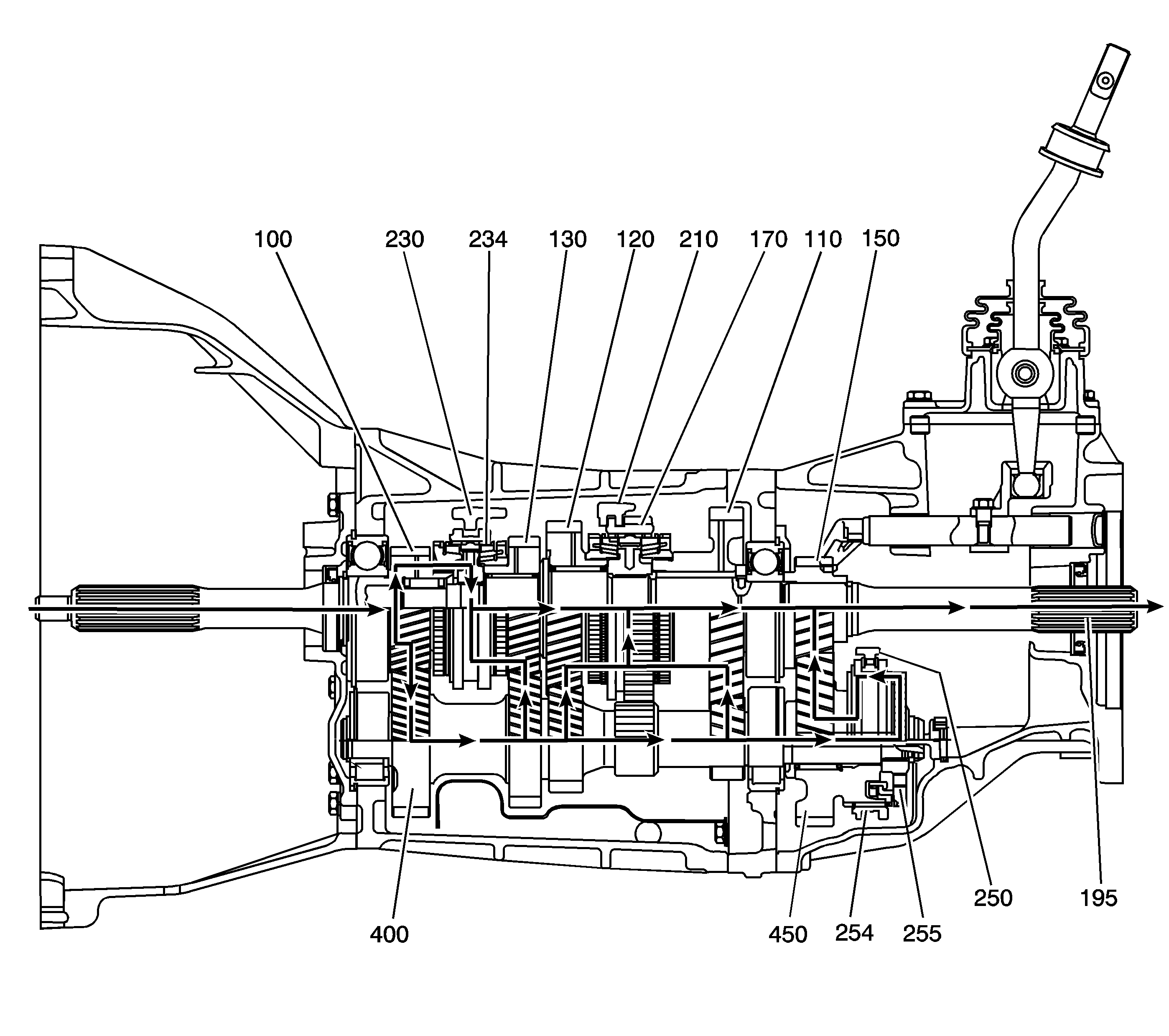
The power flow through the AR5 transmission speed gears is a basic transmission design. During 1st gear (110), 2nd gear (120) or 3rd gear (130), the input shaft (100) delivers the power from the engine to the transmission. The external teeth on the input shaft (100) engage with the front gear on the counter shaft (400). Depending on the selected gear position, the power flows from a countershaft gear to a speed gear and then through the speed gear selector teeth. The gear selector teeth engage with the synchronizer sleeve. The synchronizer sleeve is slip splined on the synchronizer hub. The synchronizer hubs are press fit on the output shaft, therefore delivering the engine power to the output shaft (195).
1st gear: Moving the 1st/2nd shift fork (210) rearward, moves the 1st/2nd synchronizer sleeve (170). The inner teeth on the synchronizer sleeve push against the blocking ring teeth, causing the synchronizer rings to contact, and the speed gear and the output shaft to match speeds. The synchronizer sleeve (170) then engages the selector teeth on 1st gear (110). Power flow is now from the input shaft (100) to the countershaft (400) to the 1st gear (110), through the synchronizer and to the output shaft (195).2nd gear: Moving the 1st/2nd shift fork (210) forward, moves the 1st/2nd synchronizer sleeve (170). The inner teeth on the synchronizer sleeve push against the blocking ring teeth, causing the synchronizer rings to contact, and the speed gear and the output shaft to match speeds. The synchronizer sleeve (170) then engages the selector teeth on 2nd gear (120). Power flow is now from the input shaft (100) to the countershaft (400) to the 2nd gear (120) through the synchronizer and to the output shaft (195).
3rd gear: Moving the 3rd/4th shift fork (230) rearward, moves the 3rd/4th synchronizer sleeve (234). The inner teeth on the synchronizer sleeve push against the blocking ring teeth, causing the synchronizer rings to contact, and the speed gear and the output shaft to match speeds. The synchronizer sleeve (234) then engages the selector teeth on 3rd gear (130). Power flow is now from the input gear (100) to the countershaft (400) to the 3rd gear (130) through the synchronizer and to the output shaft (195).
4th gear: In 4th gear, the power flow goes directly from the input shaft (100) to the output shaft (195) through the 3rd/4th synchronizer. This happens because 4th gear is the same ratio as the engine speed. When moving the 3rd/4th shift fork (230), the 3rd/4th synchronizer sleeve (234) inner teeth push against the single blocking ring teeth for 4th gear. Matching the input shaft (100) to the output shaft (195) allows the synchronizer sleeve to engage to the selector teeth on the input shaft (100).
5th gear: 5th gear is an overdrive ratio. Because 5th gear is overdrive, the 5th gear (150) is splined on the rear of the output shaft (195). The 5th countershaft gear (450) is located on the rear of the countershaft (400) and rotates on needle bearings. The 5th countershaft gear (450) is larger diameter, with more teeth than 5th gear (150). The power flow for 5th gear is from the input shaft (100) to the countershaft (400). Moving the 5th shift fork (250) rearward, the 5th/reverse synchronizer sleeve (254) pushes against the teeth on the blocking ring, forcing the blocking ring against the middle ring. The middle ring has tabs in the 5th synchronizer gear (255). The blocking rings match the speed of the 5th synchronizer gear (255) and the 5th countershaft gear (250), which is rotating by the 5th gear (150). Matching the speeds, the synchronizer sleeve slides onto the 5th synchronizer gear. Power flows from the countershaft (400) to the 5th synchronizer gear (255), through the synchronizer sleeve. With the synchronizer sleeve also engaged with the 5th countershaft gear (450), power flows from the 5th countershaft gear (450) to the 5th gear (150) and to the output shaft (195), which now turns faster than the speed of the input shaft (100).
Power Flow - Reverse Gear
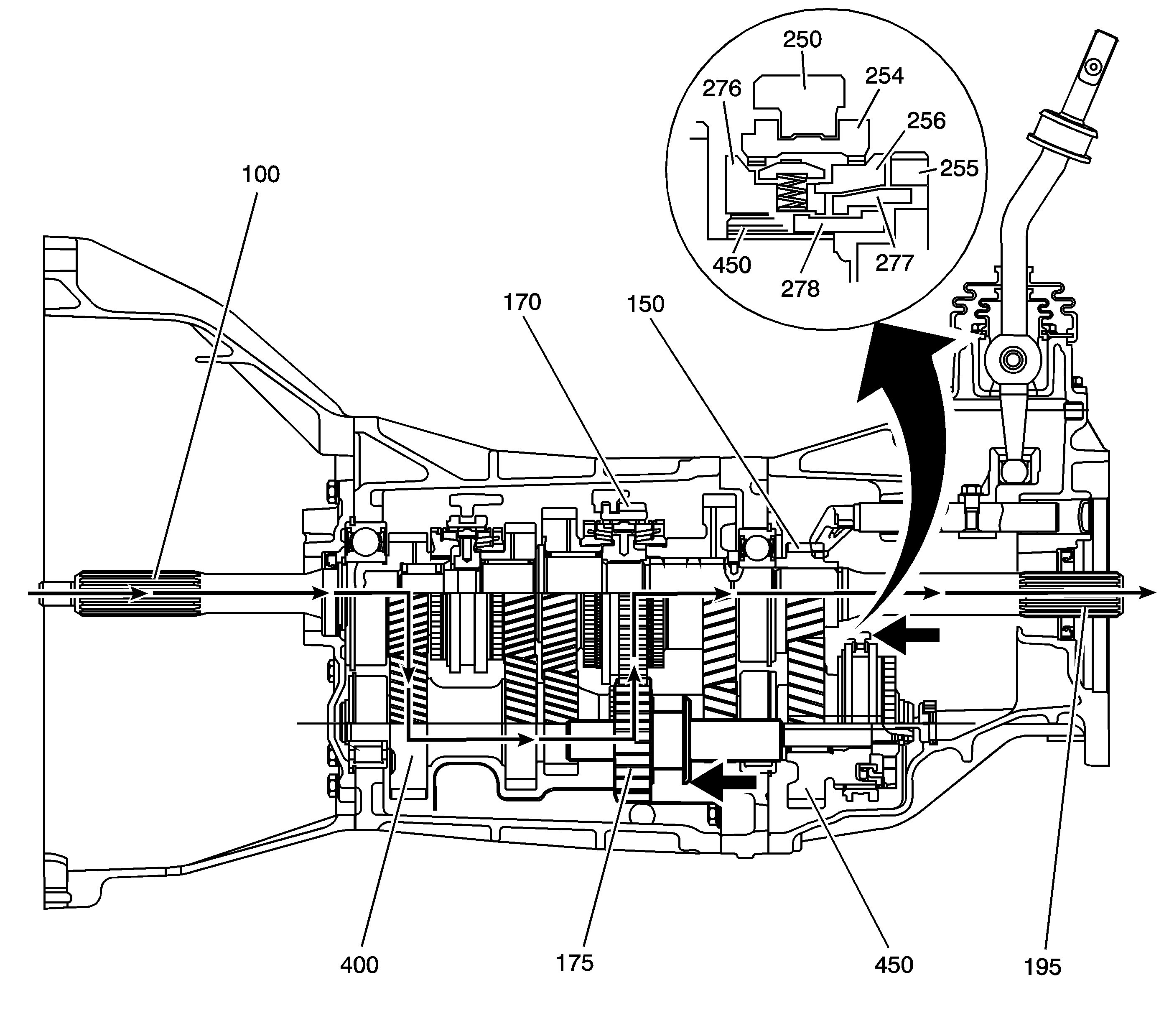
Moving the reverse shift fork forward, slides the reverse idler gear (175) forward on the reverse idler gear shaft. The reverse idler gear (175) engages with the countershaft reverse gear and with the outer or reverse gear teeth on the 1st/2nd synchronizer sleeve (170). The synchronizer sleeve is the reverse gear in this application. The synchronizer sleeve (170) is slip splined on the synchronizer hub. The synchronizer hub is pressed on the output shaft (195). The power flow in reverse is from the input shaft (100), to the countershaft (400), to the reverse idler gear (175), to the reverse gear teeth on the 1st/2nd synchronizer sleeve (170), through the synchronizer and to the output shaft (195). Using the 5th/reverse synchronizer avoids gear clash when shifting in reverse. When moving the reverse shift fork forward, simultaneously the 5th shift fork (250) moves the 5th/reverse synchronizer sleeve (254) forward. The internal splines of the synchronizer sleeve slide on the splines of the 5th countershaft gear (450). At the same time, the synchronizer sleeve splines are pushing against the teeth on the reverse gear synchronizer ring (276). The action moves the reverse gear synchronizer ring (276) forward. The reverse/5th inner ring (278), or pull ring, locking to the reverse gear synchronizer ring (276) moves forward. The reverse/5th inner ring (278) pulls forward, and tabbed lock to the reverse/5th internal ring (277) forces the reverse internal ring (277) against the 5th gear blocking ring (256). The 5th gear blocking ring (256) is moving at the same revolutions as the output shaft (195). The reverse internal ring (277), tabbed to the 5th synchronizer gear (255), is revolving at the countershaft (400) speed. The synchronizer action matches the revolutions of the countershaft (400) to output shaft (195) revolutions, allowing the reverse idler (175) to engage without gear clashing.
