Special Tools
| • | J 44221 Camshaft Holding Tool |
| • | J 45059 Angle Meter |
Removal Procedure
- Remove No. 1 cylinder spark plug. Refer to Spark Plug Replacement .
- Remove the camshaft cover. Refer to Camshaft Cover Replacement .
- Remove the exhaust camshaft position (CMP) sensor. Refer to Camshaft Position Sensor Replacement - Exhaust .
- Remove the intake CMP sensor. Refer to Camshaft Position Sensor Replacement - Intake .
- Remove the engine front cover. Refer to Engine Front Cover Replacement .
- Rotate the crankshaft in the engine rotational direction clockwise, until the #1 piston is at top dead center (TDC) on the compression stroke.
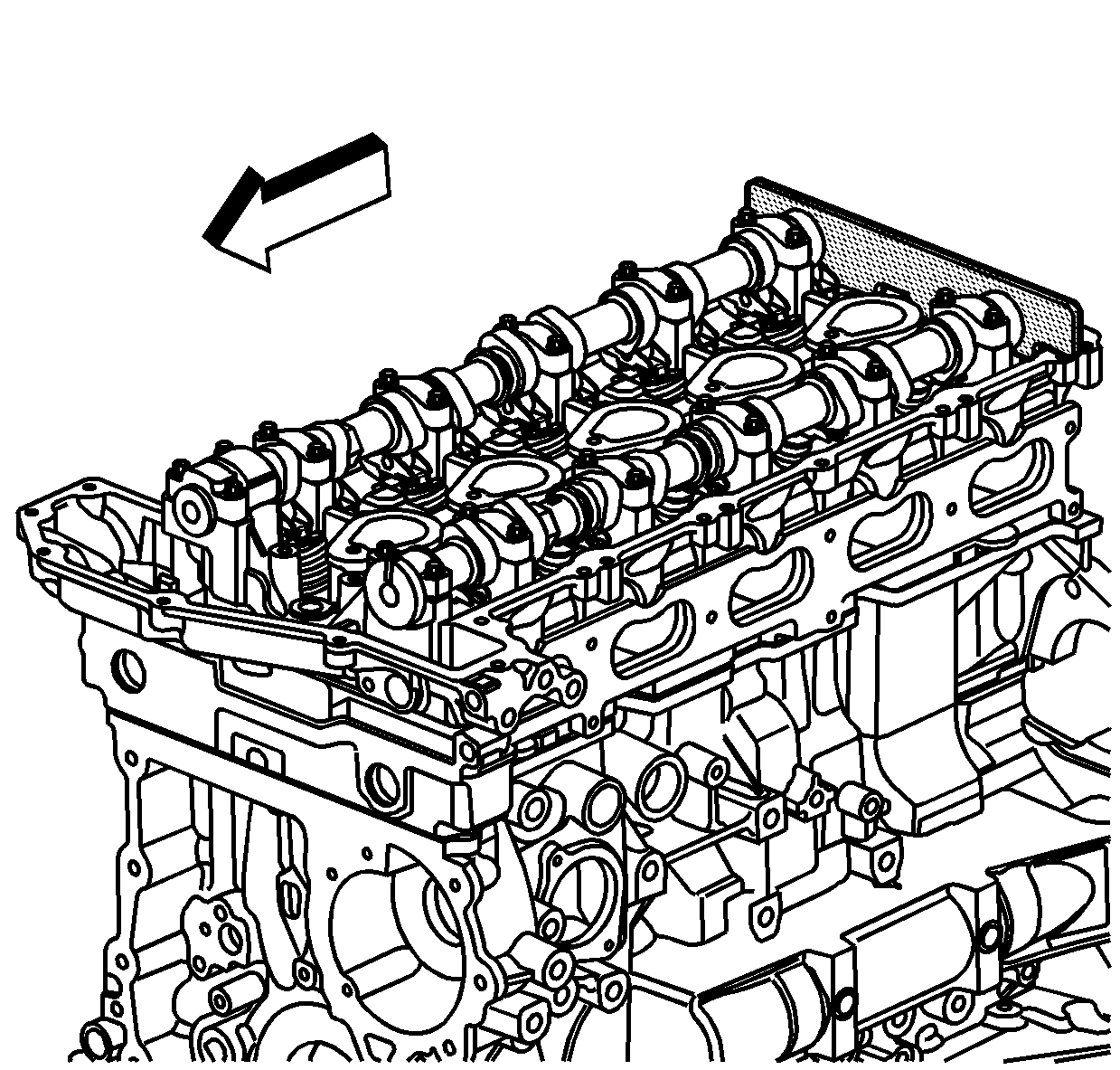
- Install the J 44221 to the rear of the camshafts.
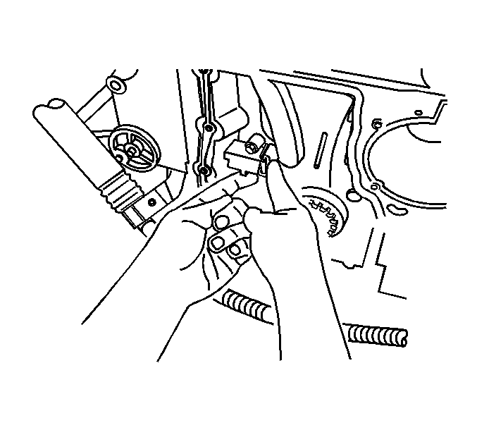
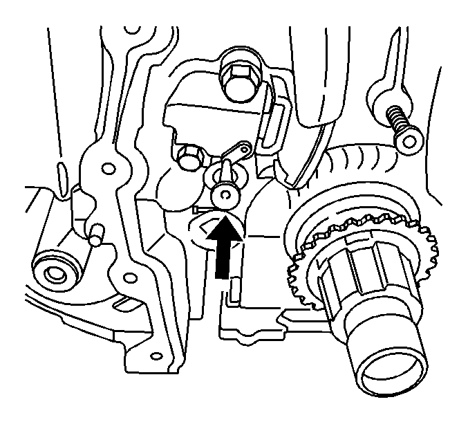
- Release the tension on the timing chain by moving the tensioner shoe in.
- Place the tee into the tensioner to hold the shoe in place.
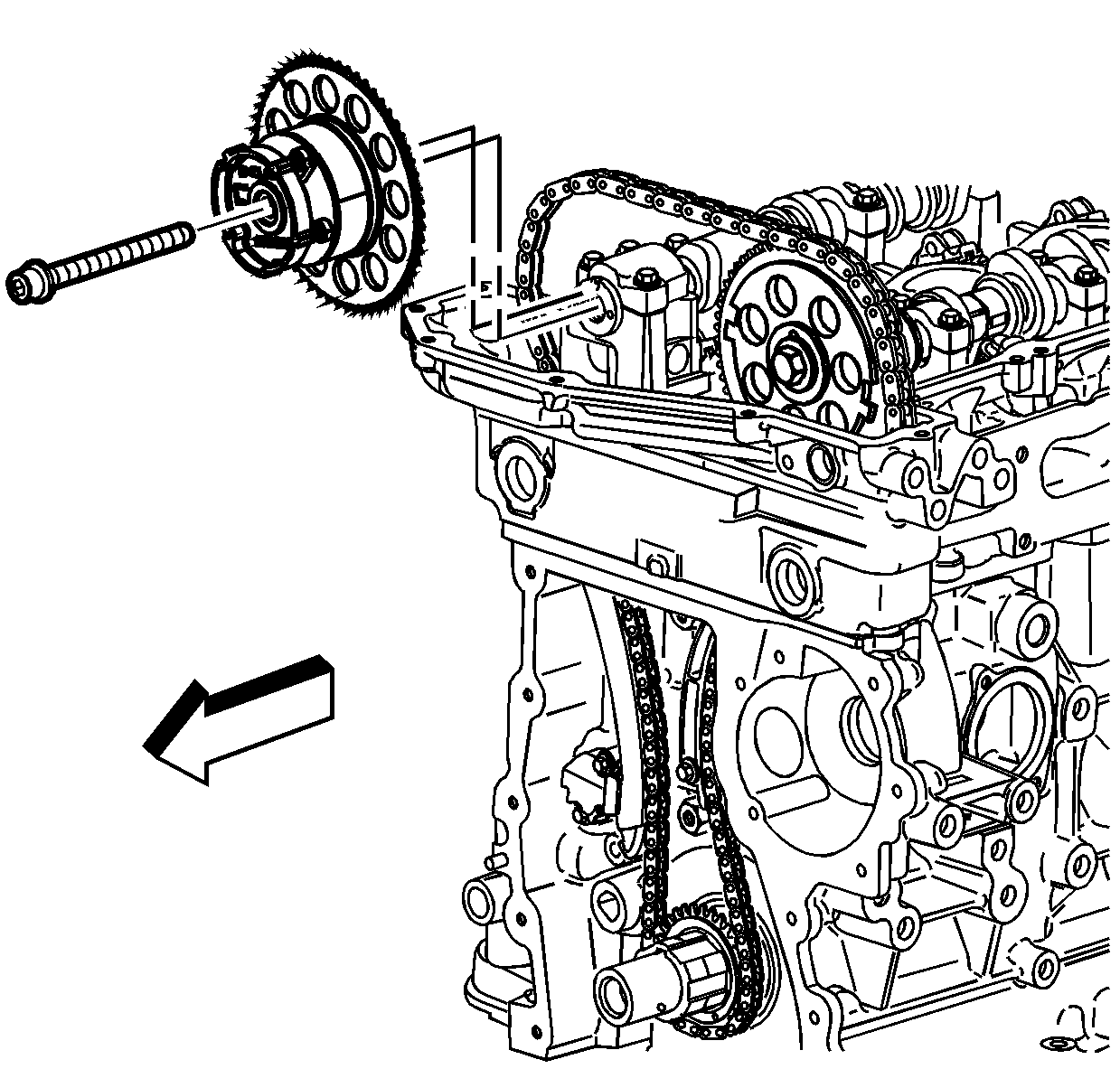
- Remove and discard the exhaust camshaft position actuator bolt.
- Remove the exhaust camshaft position actuator.
- Remove and discard the intake camshaft sprocket bolt.
- Remove the intake camshaft sprocket.
- Remove the timing chain.
- Remove the crankshaft sprocket.
- Clean and inspect the timing chain and sprockets. Refer to Camshaft Timing Chain and Sprocket Cleaning and Inspection .
Caution: Refer to Camshaft Holding Tool Caution in the Preface section.
Installation Procedure
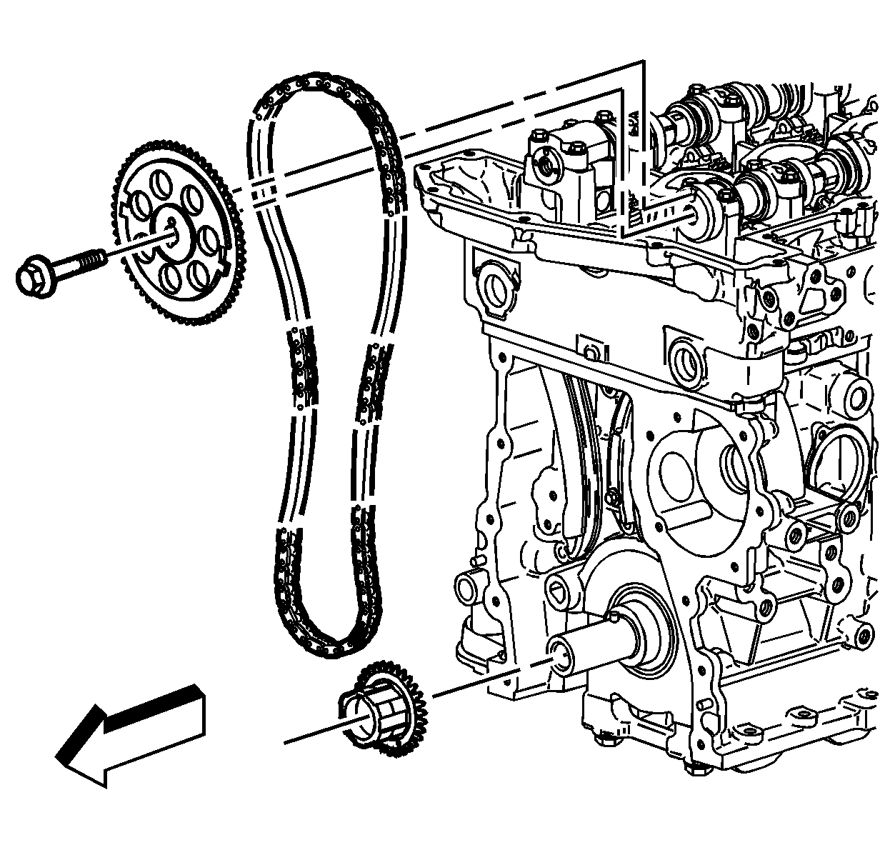
- Install the crankshaft sprocket to the crankshaft snout.
- Install the intake camshaft sprocket into the timing chain.
- Feed the timing chain down through the opening in the cylinder head.
- Install the timing chain on the crankshaft sprocket.
- Install the intake camshaft sprocket onto the intake camshaft.
- Install a NEW intake camshaft sprocket bolt.
- Ensure the camshaft actuator is functioning properly. Refer to Camshaft Position Actuator Diagnosis .
- Install the exhaust camshaft actuator into the timing chain.
- Install the exhaust camshaft actuator onto the exhaust camshaft.
- Install a NEW exhaust camshaft actuator bolt.
- Remove the tee in the timing chain tensioner in order to regain tension on the timing chain.
- Remove the J 44221 from the camshafts.
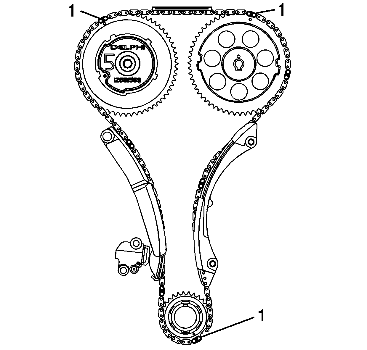
- The dark links (1) on the timing chain should be aligned with the marks on the sprockets as shown.
- Install the engine front cover. Refer to Engine Front Cover Replacement .
- Install the intake CMP sensor. Refer to Camshaft Position Sensor Replacement - Intake .
- Install the exhaust CMP sensor. Refer to Camshaft Position Sensor Replacement - Exhaust .
- Install the camshaft cover. Refer to Camshaft Cover Replacement .
- Install the No. 1 cylinder spark plug. Refer to Spark Plug Replacement .
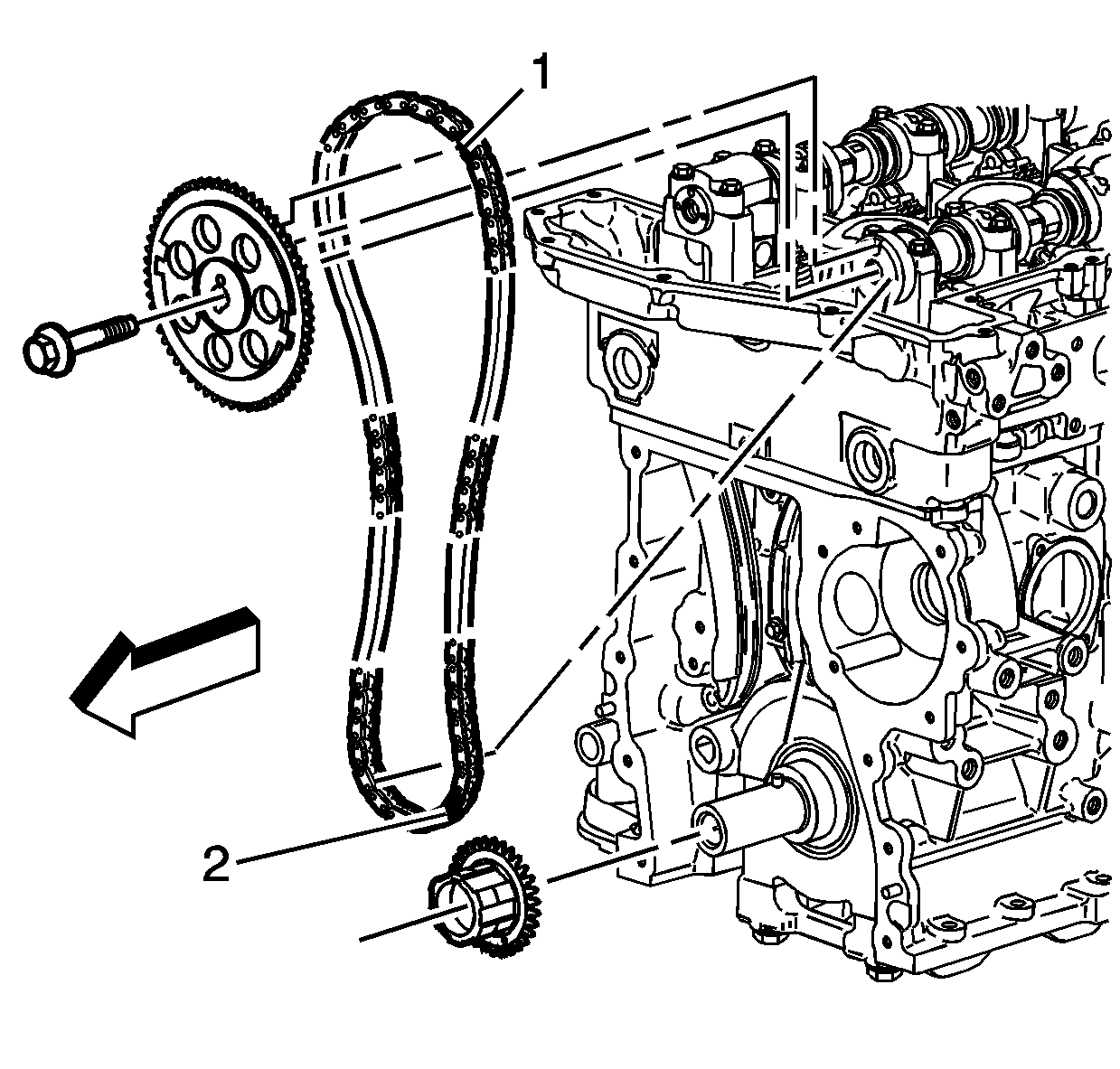
Important: Ensure the No. 1 piston is at TDC. The pin on the crankshaft for the timing chain sprocket should be straight up.
Important: Every 7th link of the timing chain is darkened to aid in aligning the timing marks.
Aligning the dark link (1) of the timing chain with the timing mark on the intake camshaft sprocket.
Align the dark link (2) of the timing chain with the timing mark on to the crankshaft sprocket.
Important: Ensure the alignment pin is properly engaged with the camshaft
Notice: Refer to Fastener Notice in the Preface section.
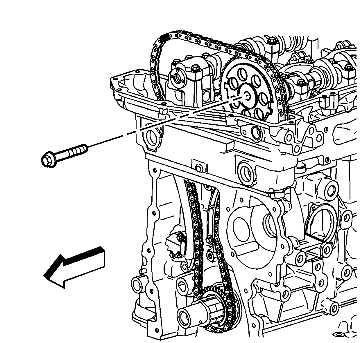
Tighten
Tighten the bolt a first pass to 20 N·m (15 lb ft). Using the
J 45059
rotate the bolt a final pass an additional 100 degrees.
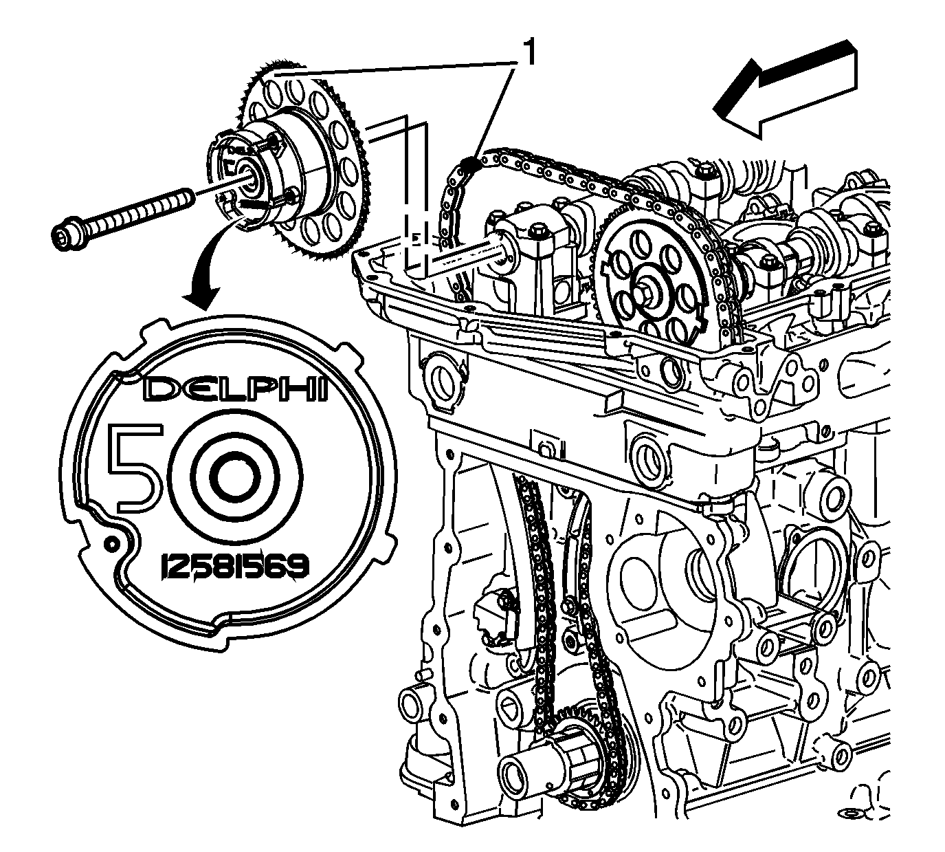
Align the dark link (1) of the timing chain with the timing mark (1) on the exhaust camshaft position actuator sprocket.
Important:
• To aid in aligning the actuator to the camshaft , use a 25 mm (1 in) wrench on the hex of the camshaft to rotate • Ensure the alignment pin is properly engaged with the camshaft

Tighten
Tighten the bolt a first pass to 25 N·m (18 lb ft). Using the
J 45059
rotate the bolt a final pass an additional 135 degrees.


