| Subject: | EI08197 -- Front Axle Rubbing, Moan or Growl Noise in 2WD May Not Occur in 4WD (Engineering Information) |
| Models: | 2008 Chevrolet Colorado |
| Built Between January 1, 2008 - April 1, 2008 |
| Attention: | Proceed with this bulletin ONLY if the customer has commented about this concern AND the EI number is listed in GMVIS. Otherwise, disregard the bulletin and proceed with diagnostics found in the published service information. THIS IS NOT A RECALL.
Refer to Corporate Bulletin Number 04-00-89-053B for more details on the use of Engineering Information bulletins. |
Condition
Important: This bulletin pertains to 4WD vehicles only, built between January 1, 2008 - April 1, 2008. For all other vehicles, refer to SI for diagnostic and repair information.
Some customers may comment on a rubbing, moan or growl noise from the front of the vehicle. The condition may be described as a noise that phases (cycles) in and out. The noise typically occurs in 2WD and is eliminated when shifted to 4WD.
Cause
GM Engineering is attempting to determine the root cause of the above condition. GM Engineering would like to receive product feedback on 2008 Chevrolet Colorado and GMC Canyon vehicles exhibiting a rubbing or growl noise from the front axle assembly.
As a result, this information will be used by engineering to "root cause" the customer's concern and develop/validate a field fix.
Correction
Document the following information on the repair order:
- Verify that the VIN and mileage are correctly recorded on the repair order.
- Verify that the vehicle was built between January 1, 2008 - April 1, 2008. Document the vehicle build date on the repair order.
- Can the noise be eliminated by activating 4WD?
| • | No -- Inspect the exhaust for contact with the torsion bar. Refer to SI for further diagnostic info -- disregard this bulletin. |
| • | Yes -- proceed with step 4. |
- Using J-39570 Chassis Ears, identify the source/location of the noise. Proceed with step 5 ONLY
if the source of the noise is identified as coming from the front axle assembly. All others should disregard this bulletin and
proceed with diagnostics found in SI.
- Is there a vibration associated with the complaint noise? If so, describe where the vibration is felt.
- Identify under what driving conditions the complaint noise is exhibited:
| • | Driving straight -- with or without suspension travel? |
| • | Left turns -- with or without suspension travel? |
| • | Right turns -- with or without suspension travel? |
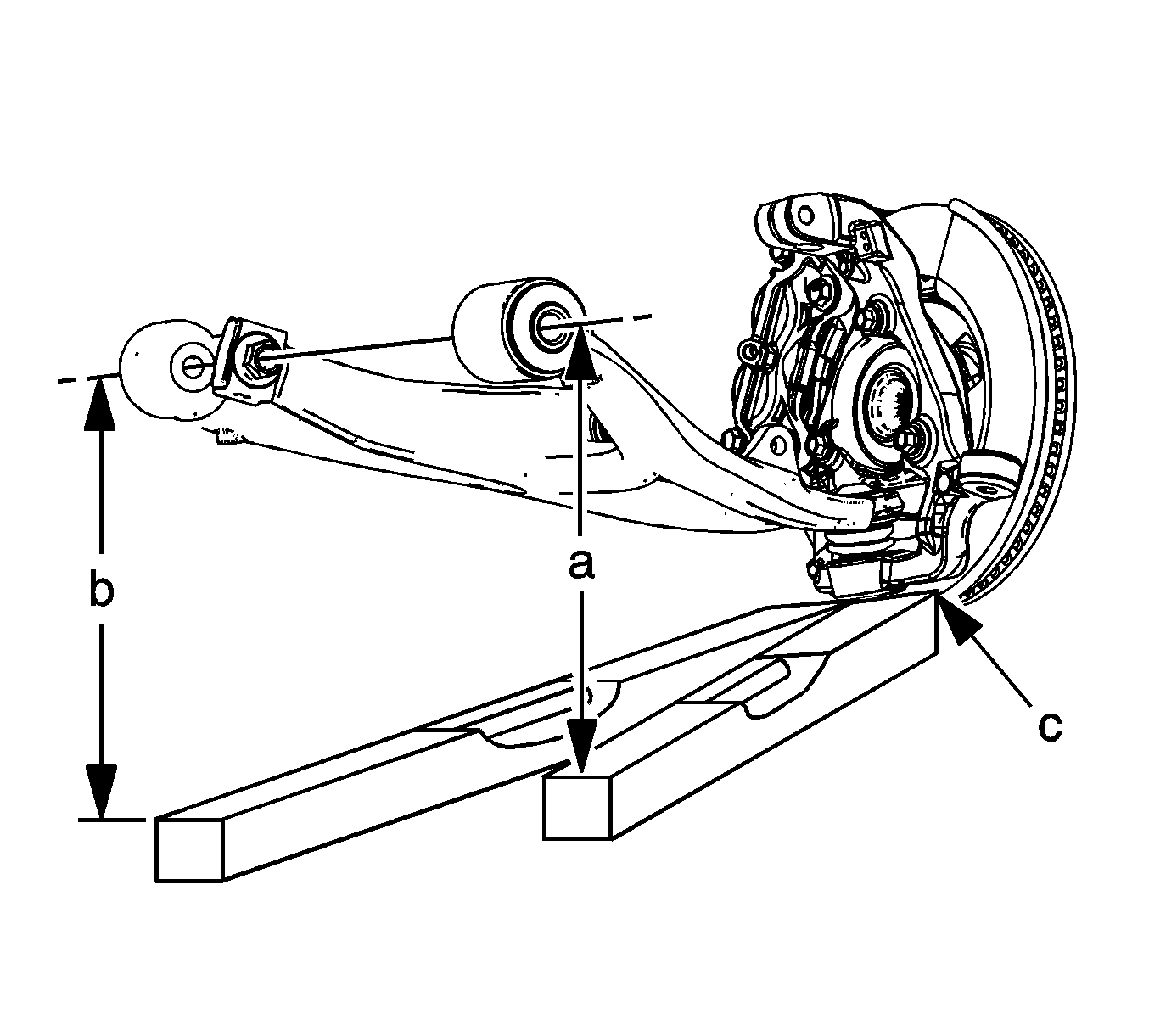
- Document the current left and right Z-height measurements. Complete the following steps to determine the current Z-height:

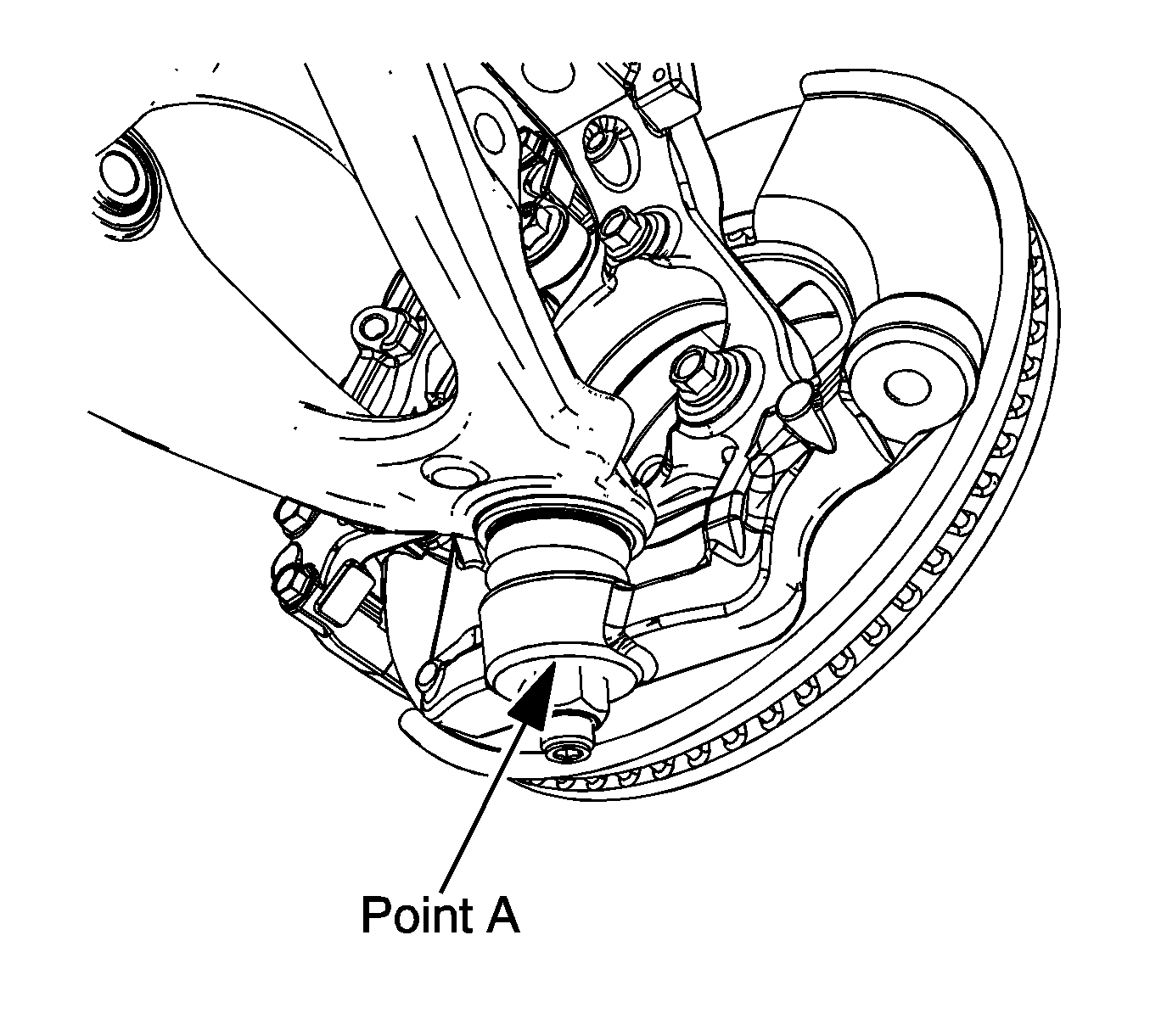
| 7.1. | Set the top edge of the level on the reference surface (Point A) of the steering knuckle. |

| 7.2. | With the level on the steering knuckle (C), extend the level directly under the rear of the front attachment bolt of the lower control arm (A). |
| 7.3. | While keeping the level in contact with the knuckle reference surface, adjust the level up or down until the bubble indicates it is horizontally level. |
| 7.4. | Extend a tape measure straight down from the center of the attachment bolt. The point where the tape measure and the level intersect is your first measurement. |
| 7.5. | Keep the top edge of the level on the reference surface of the steering knuckle (C) and move the level directly under the front end of the rear attachment bolt of the lower control arm (B). |
| 7.6. | Extend the tape measure straight down from the center of the attachment bolt. The point where the tape measure and the level intersect is your second measurement. |
| 7.7. | Average the 2 readings -- this result is your Z-height number. |
| 7.8. | Repeat steps 7.1-7.7 a total of 3 times -- documenting all results. |
| 7.9. | Average the three results - this will be the final Z-height measurement. |
| 7.10. | Repeat steps 7.1-7.9 for the other side. |
- Mark the original [torsion bar bolts] location of the original Z-height.
Important: Turn the torsion bar bolts counterclockwise to increase the Z-height. One full turn of the bolt should be equal to 1/8" / 3.175 mm.
- Raise the Z-height of the vehicle front end to the maximum allowable specification (122 mm).
- Test drive the vehicle - does the noise disappear
?
| • | No -- proceed to step 12. |
| • | Yes -- proceed to step 11. |
- Reset the Z-height to the original measurements. Does the noise reappear
?
| • | No -- proceed to step 18. |
| • | Yes -- raise the Z-height once again to fix the condition. No further repairs are required. Proceed to step 18. |
- Mark the current location of the front axle. Disconnect the left side half shaft by popping out the half shaft snap ring from the axle
. Do not completely remove the half shaft. Loosen the front axle mounts and move the axle
as far as possible to the right hand side. Retighten the mounts to 152 N·m(112 lb ft). Does the noise disappear
?
| • | No -- proceed to step 14. |
| • | Yes -- proceed to step 13. |
- Move the axle to the original position. Does the noise reappear
?
| • | No -- proceed to step 18. |
| • | Yes -- move the axle to the right hand side to fix the concern. No further repairs are required. Proceed to step 18. |
- Reset the Z-height to the original measurements. Mark the original position and orientation between the axle and half shaft. Remove the left hand side half shaft and reinstall. Does the noise disappear
?
| • | No -- proceed to step 15. |
| • | Yes -- proceed to step 18. |
- Remove the left hand side half shaft. Rotate the half shaft clockwise 90° and reinstall. Does the noise disappear
?
| • | No -- proceed to step 16. |
| • | Yes -- return shaft to the original position. Does the noise reappear
? |
| - | No -- proceed with step 18. |
| - | Yes -- mark the original position and clocked position. Replace the half shaft. The original part will be requested back using the WPC Part Return Process. Proceed to step 18. |
- Disconnect and disassemble the axle. Inspect for wear patterns on the half shaft, clutch gear, I/O shaft, thrust washers and I/O shaft - clutch gear teeth. Note any unusual wear on the repair order. Reassemble and reinstall the axle. Is the
noise still present?
| • | No -- proceed to step 18. |
| • | Yes -- proceed to step 17. |
- Grease the interface between the I/O shaft and the half shaft. Does the noise disappear
?
| • | No -- Proceed to step 18. |
| • | Yes -- Clean out the grease. Does the noise reappear
? |
| - | No -- proceed with step 18. |
| - | Yes -- regrease the interface between the I/O shaft and the half shaft to correct the concern. No further repairs are required. Proceed with step 18. |
- Contact the either of the following engineers to report findings:
Engineer
| Phone #
|
Mark Ludescher
| 248-685-4084
|
Joe Leland
| 318-208-2087
|
If the engineers are unable to take your call, leave the following information in a message:
| • | Dealer Name and Phone Number
|
| • | Complete VIN and Repair Order Number
|
If the engineer does not return your call within one hour, proceed with diagnosis and repair of vehicle.
Warranty Information
For vehicles repaired under warranty, use:
Labor Operation
| Description
| Labor Time
|
F9719*
| Engineering Information - Front Axle
| 1.3 hrs
|
Add
| Move Axle Assembly to the Right
| 0.3 hr
|
Add
| Remove and Reinstall Half Shaft
| 1.0 hr
|
Add
| Rotate Axle Assembly 90 Degrees
| 0.9 hr
|
Add
| Disassemble, Inspect and Reinstall Axle / Half Shaft
| 5.0 hrs
|
*This labor operation number is for bulletin use only. This number will not be published in the Labor Time Guide.
|


