Transmission Replacement 2WD 2.9L and 3.7L
Special Tools
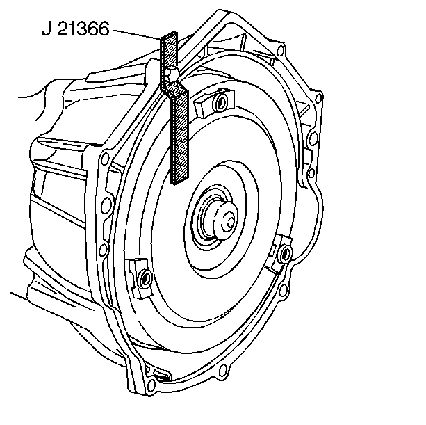
J 21366 Converter Holding Strap
Removal Procedure
- Ensure the vehicle is in the PARK position.
- Remove the filler tube. Refer to Transmission Fluid Filler Tube and Seal Replacement.
- Drain the transmission fluid if necessary. Refer to Automatic Transmission Fluid and Filter Replacement.
- Remove the rear propeller shaft. Refer to One-Piece Propeller Shaft Replacement or Two-Piece Propeller Shaft Replacement.
- Complete the following in order to disconnect the range selector cable (3) from the transmission range selector lever ball stud.
- Remove the retainer (4) from the range selector cable (3).
- Push the range selector cable locking tabs inward toward each other to release from the bracket (2).
- Disconnect the following engine wiring harness electrical connectors:
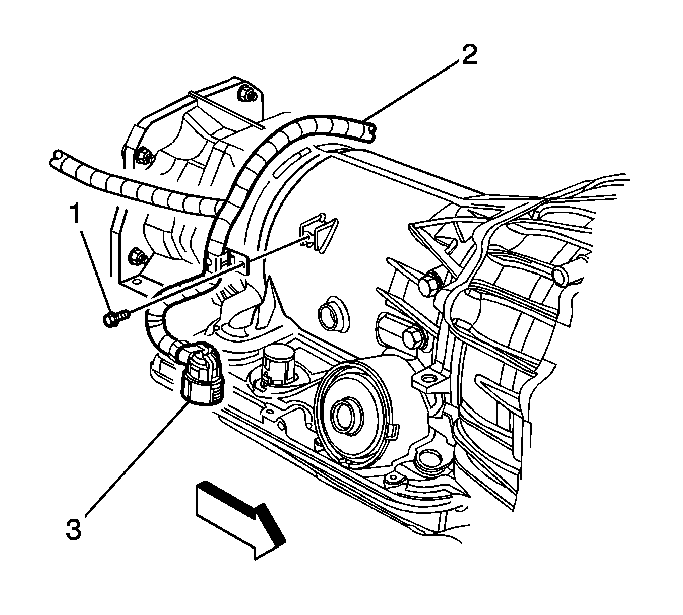
- Remove the screw (4) securing the engine wiring harness (3) to the right side of the transmission, and position the harness over the transmission.
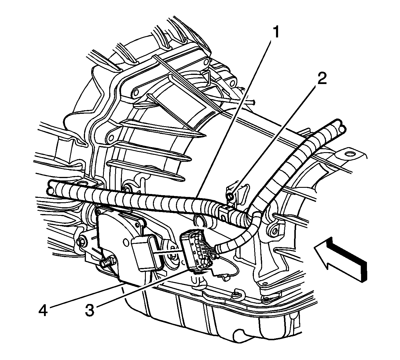
- Disconnect the park/neutral back up switch electrical connector (3).
- Remove the screw (2) securing the engine wiring harness (1) to the left side of the transmission, and position the wiring harness aside.
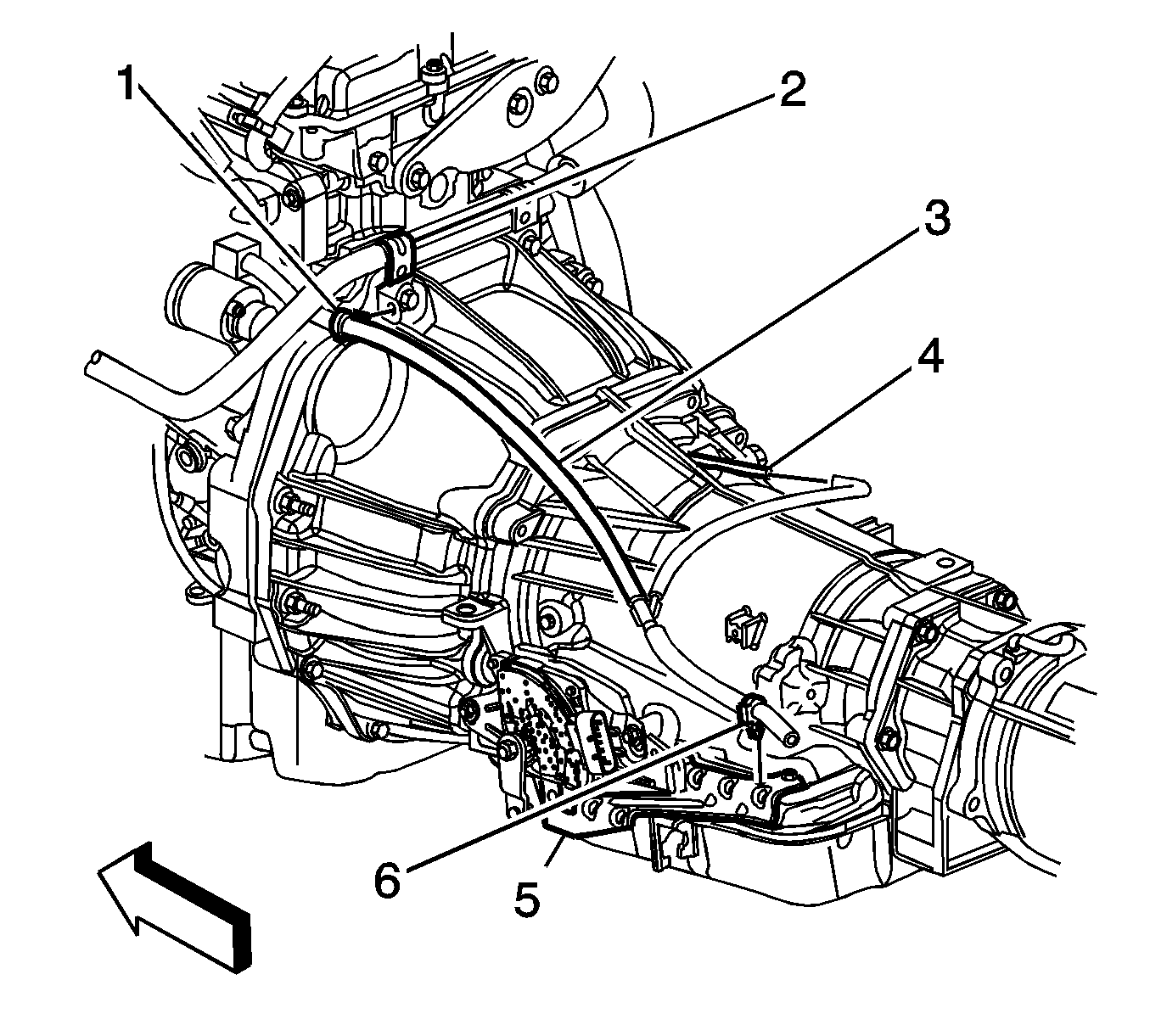
- Disconnect the transmission vent hose retainer (1) from the heater pipe bracket (2).
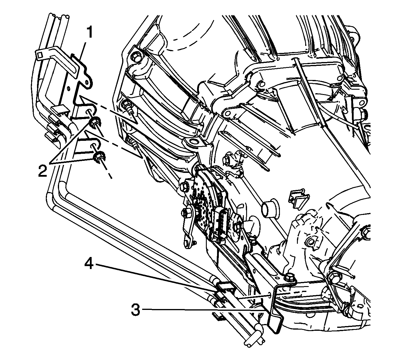
- Remove the nuts (2) securing the fuel hose/pipe bracket (1) to the transmission.
- Disconnect the fuel hose/pipe retainer (4) from the range selector cable bracket (3), and position aside the fuel hose/pipe bundle.
- Remove the inspection plug (3) from the transmission (1).
- Mark the torque converter to flexplate/flywheel orientation to ensure proper realignment.
- Remove the engine protection shield in order to access the harmonic balancer bolt. Refer to Engine Protection Shield Replacement.
- Remove the service slot plug.
- Repeat the following steps for all 3 torque converter bolts:
- Place an oil pan under the transmission fluid cooler pipes.
- Disconnect the transmission oil cooler pipes from the transmission ONLY. Refer to Transmission Fluid Cooler Hose/Pipe Replacement.
- Plug the open outlet ports to prevent fluid loss and contamination.
- Support and secure the transmission using a suitable transmission jack.
- Remove the transmission crossmember. Refer to Transmission Support Crossmember Replacement.
- Remove the 9 transmission mounting bolts.
- Remove the remaining transmission mounting bolts (2).
- Using the transmission jack, carefully lower the transmission from the vehicle.
- Install the J 21366 onto the transmission bell housing to retain the torque converter.
- Perform the flush and flow test on the automatic transmission oil cooler. Refer to Transmission Fluid Cooler Flushing and Flow Test.
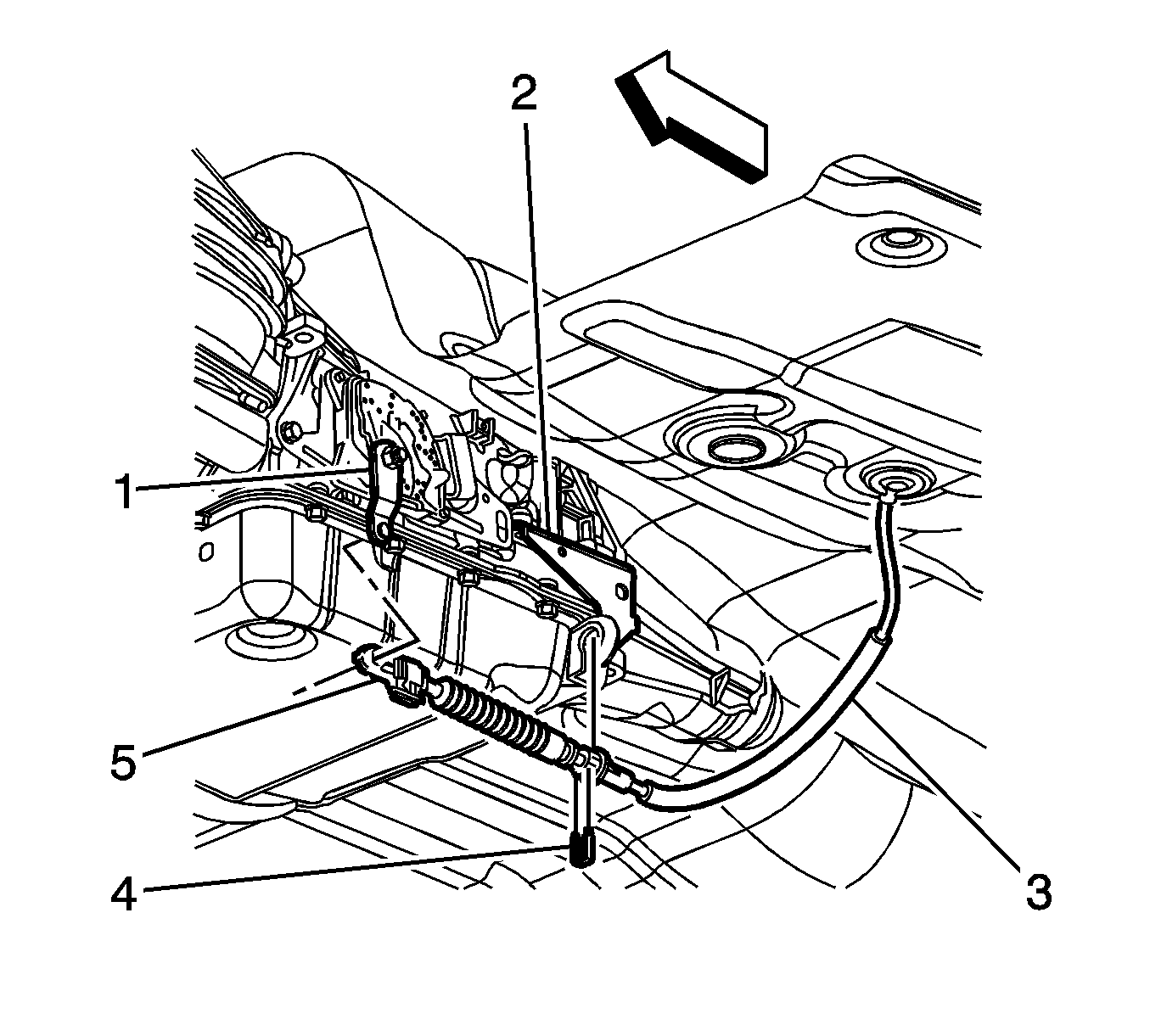
Note: Do not pull on the boot portion of the cable.
| 5.1. | Insert a flat-bladed tool between the range selector cable end (5) and the range selector lever (1). |
| 5.2. | Pry the range selector cable end (5) away from the range selector lever (1). |
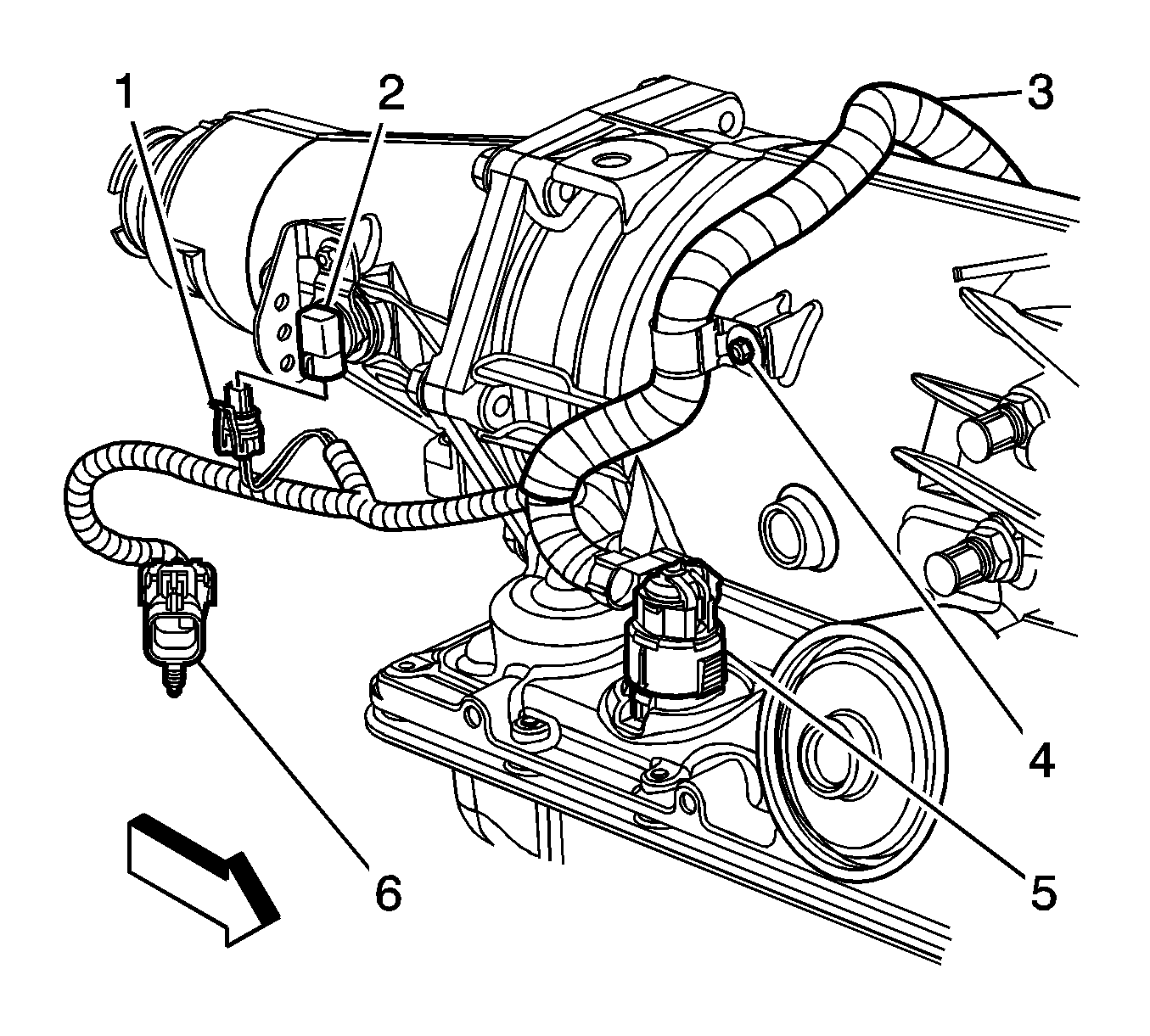
| • | The heated oxygen sensor (6) |
| • | The transmission main connector (5) |
| • | The vehicle speed sensor (VSS) (1) |
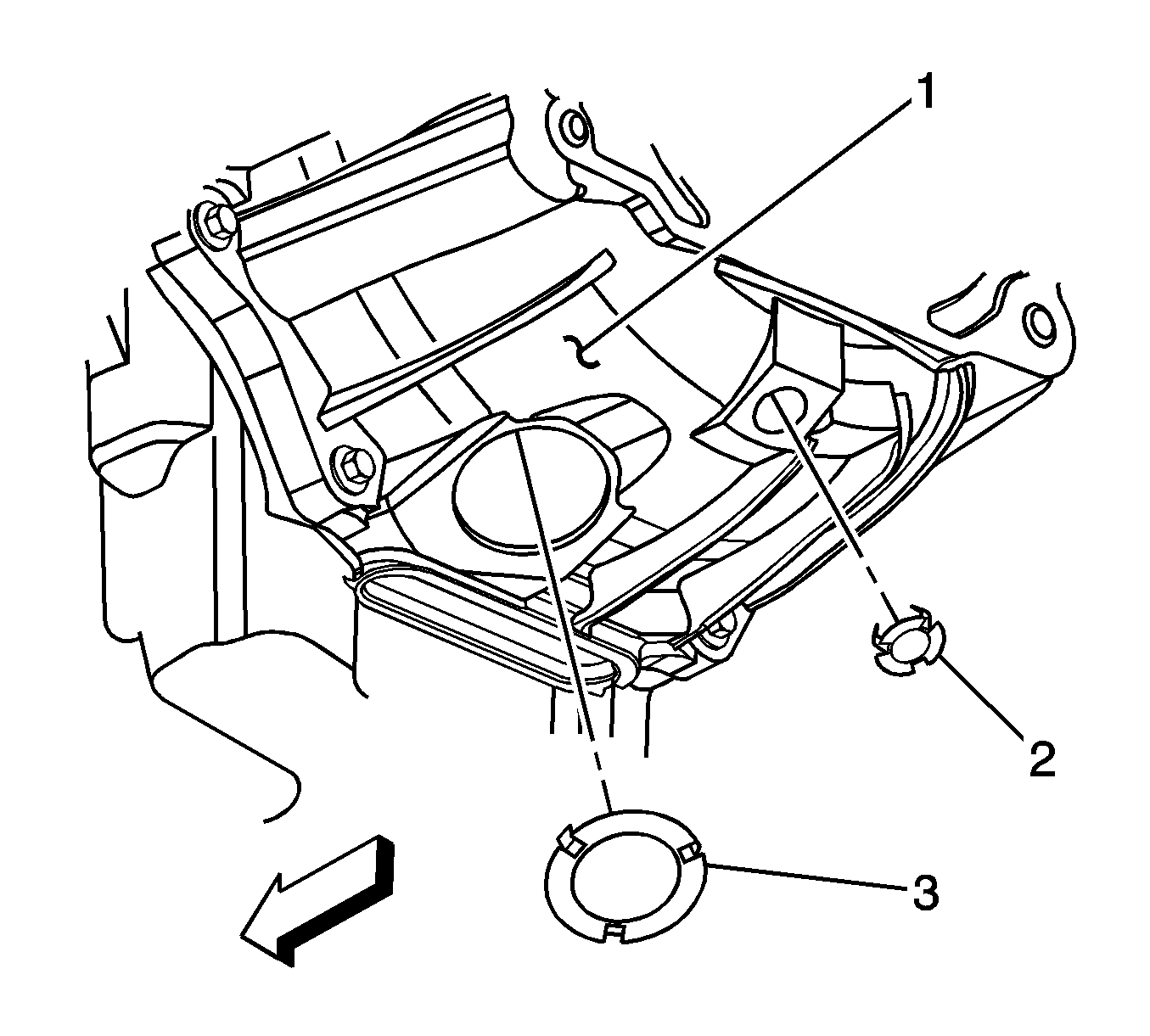
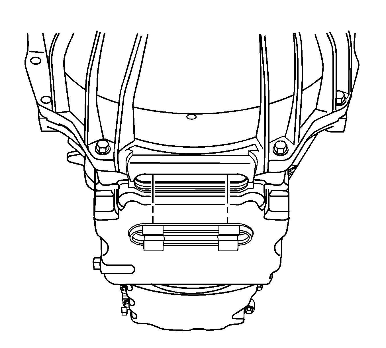
| 19.1. | Rotate the harmonic balancer center bolt clockwise ONLY, in order to access the torque converter bolt through the service slot. |
| 19.2. | Remove the torque converter bolt using one of the following: |
| • | 18 mm crowfoot wrench |
| • | Short T50 TORX bit |
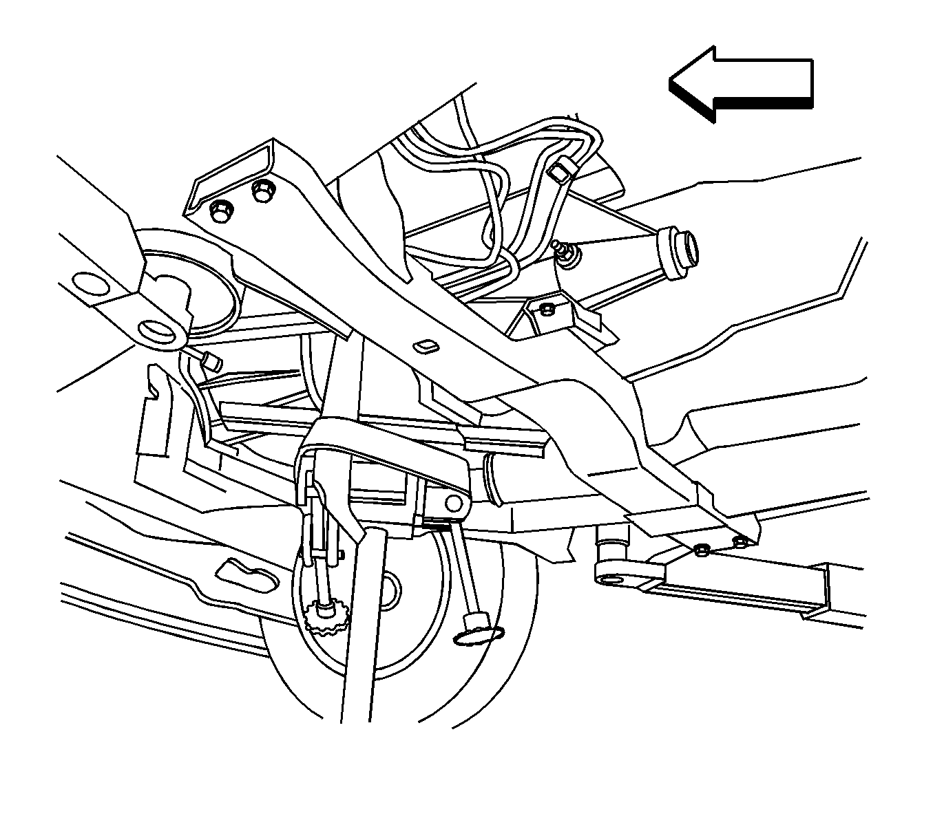
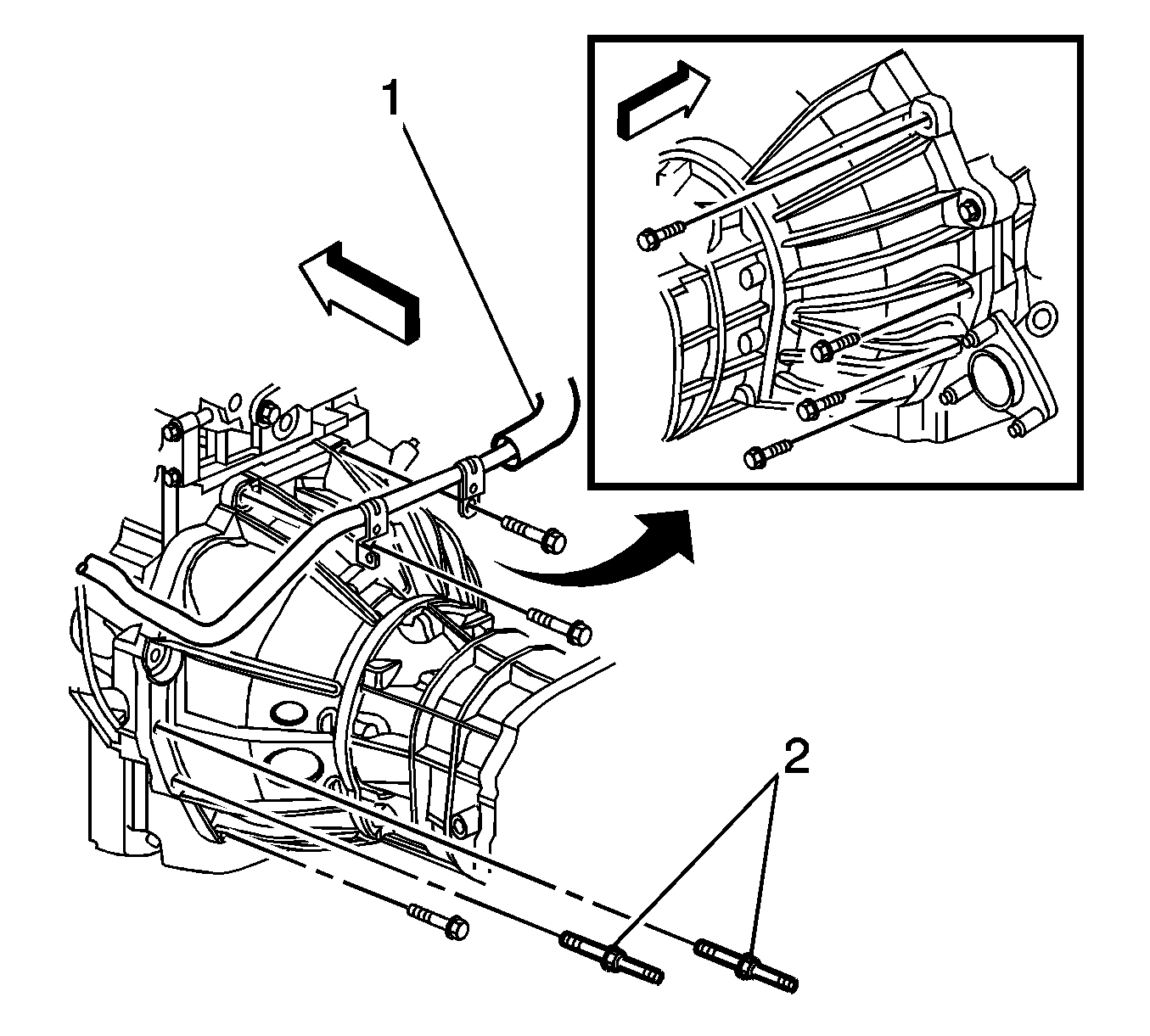
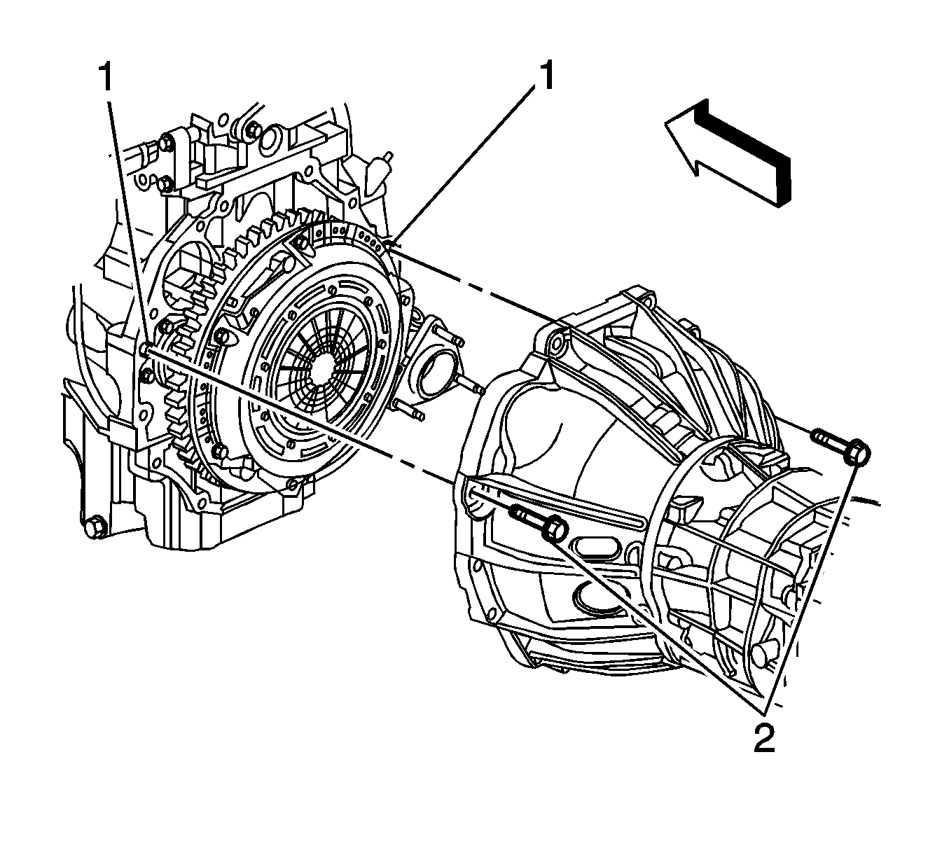

Note: Ensure clearance is maintained between the transmission and the following:
• The catalytic converter • The engine wiring harness • The fuel hose/pipe brackets • The heater pipe • The transmission oil cooler pipes
Installation Procedure
- Remove the J 21366 from the transmission.
- Ensure the torque converter is fully engaged with the transmission oil pump.
- Using the transmission jack, carefully raise the transmission to the engine.
- Align the transmission with the engine dowels (1).
- Install the 2 transmission mounting bolts (2).
- Install the remaining transmission mounting bolts.
- Install the transmission crossmember. Refer to Transmission Support Crossmember Replacement.
- Remove the transmission jack from under the vehicle.
- Connect the transmission oil cooler pipes to the transmission. Refer to Transmission Fluid Cooler Hose/Pipe Replacement.
- Align the torque converter to flexplate/flywheel orientation marks made during the removal procedure.
- Repeat the following steps for all 3 torque converter bolts:
- Install the inspection plug (3) to the transmission (1).
- Install the service slot plug.
- Install the nuts (2) securing the fuel hose/pipe bracket (1) to the transmission.
- Connect the fuel hose/pipe retainer (4) to the range selector cable bracket (3).
- Connect the transmission vent hose retainer (1) to the heater pipe bracket (2).
- Install the screw (1) securing the engine wiring harness (2) to the left side of the transmission.
- Connect the park/neutral back up switch electrical connector (3).
- Lay the engine wiring harness over the transmission.
- Connect the following engine wiring harness electrical connectors:
- Install the screw (4) securing the engine wiring harness (3) to the right side of the transmission.
- Install the range selector cable (3) to the bracket (2).
- Install the retainer (4) to the range selector cable (3).
- Adjust the automatic transmission range selector cable. Refer to Range Selector Lever Cable Adjustment.
- Install the rear propeller shaft. Refer to One-Piece Propeller Shaft Replacement or Two-Piece Propeller Shaft Replacement.
- Install the engine protection shield. Refer to Engine Protection Shield Replacement.
- Install the filler tube. Refer to Transmission Fluid Filler Tube and Seal Replacement.
- Fill the transmission fluid if necessary. Refer to Automatic Transmission Fluid and Filter Replacement.
- Lower the vehicle.


Note: Ensure clearance is maintained between the transmission and the following:
• The catalytic converter • The engine wiring harness • The fuel hose/pipe brackets • The heater pipe • The transmission oil cooler pipes

Caution: Refer to Fastener Caution in the Preface section.
Note: Ensure the torque converter turns freely while tightening the transmission mounting bolts.
Tighten
Tighten the transmission mounting bolts to 50 N·m (37 lb ft).

Note:
• Ensure the studded mounting bolts (2) are located in the correct position. • The heater pipe (1) must be secured with the 2 upper mounting bolts.
Tighten
Tighten the transmission mounting bolts to 50 N·m (37 lb ft).
| 11.1. | Rotate the harmonic balancer center bolt clockwise ONLY, in order to access the torque converter bolt holes in the flexplate/flywheel through the service slot. |
| 11.2. | To aid in alignment of the torque converter to the flexplate/flywheel. Install all 3 torque converter bolts before fully tightening using one of the following: |
Tighten
Tighten the torque converter bolts to 60 N·m (44 lb ft).
| • | 18 mm crowfoot wrench |
| • | Short T50 TORX bit |


Tighten
Tighten the fuel hose/pipe bracket nuts to 20 N·m (15 lb ft).


Tighten
Tighten the engine wiring harness retainer to transmission screw to 9 N·m (80 lb in).

| • | The heated oxygen sensor (6) |
| • | The transmission main connector (5) |
| • | The vehicle speed sensor (VSS) (1) |
Tighten
Tighten the engine wiring harness retainer to transmission screw to 9 N·m (80 lb in).

Transmission Final Test and Inspection
Complete the following procedure after the transmission is installed in the vehicle:
- With the ignition OFF or disconnected, crank the engine several times. Listen for any unusual noises or evidence that any parts are binding.
- Place transmission in neutral, start the engine and listen for any unusual noises or evidence that any parts are binding.
- While the engine continues to idle raise and support the vehicle. Refer to Lifting and Jacking the Vehicle.
- Perform a final inspection for the proper fluid level. Refer to Transmission Fluid Check.
- Lower the vehicle.
- Reset the TAP values. Refer to Transmission Adaptive Functions.
- Road test the vehicle.
Note: It is recommended that transmission adaptive pressure (TAP) information be reset.
Resetting the TAP values using a scan tool will erase all learned values in all cells. As a result, The ECM, PCM or TCM will need to relearn TAP values. Transmission performance may be affected as new TAP values are learned.Transmission Replacement 4WD 2.9L and 3.7L
Special Tools
J 21366 Converter Holding Strap
Removal Procedure
- Ensure the vehicle is in the PARK position.
- Remove the filler tube. Refer to Transmission Fluid Filler Tube and Seal Replacement.
- Drain the transmission fluid if necessary. Refer to Automatic Transmission Fluid and Filter Replacement.
- Remove the transfer case assembly. Refer to Transfer Case Assembly Replacement.
- Complete the following in order to disconnect the range selector cable (3) from the transmission range selector lever ball stud.
- Remove the retainer (4) from the range selector cable (3).
- Push the range selector cable locking tabs inward toward each other to release from the bracket (2).
- Disconnect the transmission main electrical connector (3).
- Remove the screw (1) securing the engine wiring harness (2) to the right side of the transmission, and position the harness over the transmission.
- Disconnect the park/neutral back up switch electrical connector (3).
- Remove the screw (2) securing the engine wiring harness (1) to the left side of the transmission, and position the wiring harness aside.
- Disconnect the transmission vent hose retainer (1) from the heater pipe bracket (2).
- Remove the nuts (2) securing the fuel hose/pipe bracket (1) to the transmission.
- Disconnect the fuel hose/pipe retainer (4) from the range selector cable bracket (3), and position aside the fuel hose/pipe bundle.
- Remove the inspection plug (3) from the transmission (1).
- Mark the torque converter to flexplate/flywheel orientation to ensure proper realignment.
- Remove the engine protection shield in order to access the harmonic balancer bolt. Refer to Engine Protection Shield Replacement.
- Remove the service slot plug.
- Repeat the following steps for all 3 torque converter bolts:
- Place an oil pan under the transmission fluid cooler pipes.
- Disconnect the transmission oil cooler pipes from the transmission ONLY. Refer to Transmission Fluid Cooler Hose/Pipe Replacement.
- Plug the open outlet ports to prevent fluid loss and contamination.
- Support and secure the transmission using a suitable transmission jack.
- Remove the transmission crossmember. Refer to Transmission Support Crossmember Replacement.
- Remove the 7 transmission mounting bolts and 2 mounting studs (2).
- Remove the remaining transmission mounting bolts (2).
- Using the transmission jack, carefully lower the transmission from the vehicle.
- Install the J 21366 onto the transmission bell housing to retain the torque converter.
- Perform the flush and flow test on the automatic transmission oil cooler. Refer to Transmission Fluid Cooler Flushing and Flow Test.

Note: Do not pull on the boot portion of the cable.
| 5.1. | Insert a flat-bladed tool between the range selector cable end (5) and the range selector lever (1). |
| 5.2. | Pry the range selector cable end (5) away from the range selector lever (1). |


| 19.1. | Rotate the harmonic balancer center bolt clockwise ONLY, in order to access the torque converter bolt through the service slot. |
| 19.2. | Remove the torque converter bolt using one of the following: |
| • | 18 mm crowfoot wrench |
| • | Short T50 TORX bit |


Note: Ensure clearance is maintained between the transmission and the following:
• The catalytic converter • The engine wiring harness • The fuel hose/pipe brackets • The heater pipe • The transmission oil cooler pipes

Installation Procedure
- Remove the J 21366 from the transmission.
- Ensure the torque converter is fully engaged with the transmission oil pump.
- Using the transmission jack, carefully raise the transmission to the engine.
- Align the transmission with the engine dowels (1).
- Install the 2 transmission mounting bolts (2).
- Install the remaining transmission mounting bolts.
- Install the transmission crossmember. Refer to Transmission Support Crossmember Replacement.
- Remove the transmission jack from under the vehicle.
- Connect the transmission oil cooler pipes to the transmission. Refer to Transmission Fluid Cooler Hose/Pipe Replacement.
- Align the torque converter to flexplate/flywheel orientation marks made during the removal procedure.
- Repeat the following steps for all 3 torque converter bolts:
- Install the inspection plug (3) to the transmission (1).
- Install the service slot plug.
- Install the nuts (2) securing the fuel hose/pipe bracket (1) to the transmission.
- Connect the fuel hose/pipe retainer (4) to the range selector cable bracket (3).
- Connect the transmission vent hose retainer (1) to the heater pipe bracket (2).
- Install the screw (1) securing the engine wiring harness (2) to the left side of the transmission.
- Connect the park/neutral back up switch electrical connector (3).
- Lay the engine wiring harness over the transmission.
- Connect the transmission main electrical connector (3).
- Install the screw (1) securing the engine wiring harness (2) to the right side of the transmission.
- Install the range selector cable (3) to the bracket (2).
- Install the retainer (4) to the range selector cable (3).
- Adjust the automatic transmission range selector cable. Refer to Range Selector Lever Cable Adjustment.
- Install the transfer case assembly. Refer to Transfer Case Assembly Replacement.
- Install the engine protection shield. Refer to Engine Protection Shield Replacement.
- Install the filler tube. Refer to Transmission Fluid Filler Tube and Seal Replacement.
- Fill the transmission fluid if necessary. Refer to Automatic Transmission Fluid and Filter Replacement.
- Lower the vehicle.

Note: Ensure clearance is maintained between the transmission and the following:
• The catalytic converter • The engine wiring harness • The fuel hose/pipe brackets • The heater pipe • The transmission oil cooler pipes

Caution: Refer to Fastener Caution in the Preface section.
Note: Ensure the torque converter turns freely while tightening the transmission mounting bolts.
Tighten
Tighten the transmission mounting bolts to 50 N·m (37 lb ft).

Note:
• Ensure the studded mounting bolts (2) are located in the correct position. • The heater pipe (1) must be secured with the 2 upper mounting bolts.
Tighten
Tighten the transmission mounting bolts to 50 N·m (37 lb ft).
| 11.1. | Rotate the harmonic balancer center bolt clockwise ONLY, in order to access the torque converter bolt holes in the flexplate/flywheel through the service slot. |
| 11.2. | To aid in alignment of the torque converter to the flexplate/flywheel, install all 3 torque converter bolts before fully tightening using one of the following: |
Tighten
Tighten the torque converter bolts to 60 N·m (44 lb ft).
| • | 18 mm crowfoot wrench |
| • | Short T50 TORX bit |


Tighten
Tighten the fuel hose/pipe bracket nuts to 20 N·m (15 lb ft).


Tighten
Tighten the engine wiring harness retainer to transmission screw to 9 N·m (80 lb in).

Tighten
Tighten the engine wiring harness retainer to transmission screw to 9 N·m (80 lb in).

Transmission Final Test and Inspection
Complete the following procedure after the transmission is installed in the vehicle:
- With the ignition OFF or disconnected, crank the engine several times. Listen for any unusual noises or evidence that any parts are binding.
- Place transmission in neutral, start the engine and listen for any unusual noises or evidence that any parts are binding.
- While the engine continues to idle raise and support the vehicle. Refer to Lifting and Jacking the Vehicle.
- Perform a final inspection for the proper fluid level. Refer to Transmission Fluid Check.
- Lower the vehicle.
- Reset the TAP values. Refer to Transmission Adaptive Functions.
- Road test the vehicle.
Note: It is recommended that transmission adaptive pressure (TAP) information be reset.
Resetting the TAP values using a scan tool will erase all learned values in all cells. As a result, The ECM, PCM or TCM will need to relearn TAP values. Transmission performance may be affected as new TAP values are learned.Transmission Replacement 4WD 5.3L
Special Tools
J 21366 Converter Holding Strap
Removal Procedure
- Ensure the vehicle is in the park position.
- Remove the filler tube. Refer to Transmission Fluid Filler Tube and Seal Replacement.
- Remove the right and left catalytic converters. Refer to Catalytic Converter Replacement - Right Side and Catalytic Converter Replacement - Left Side.
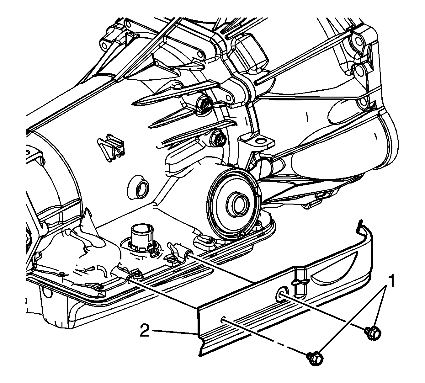
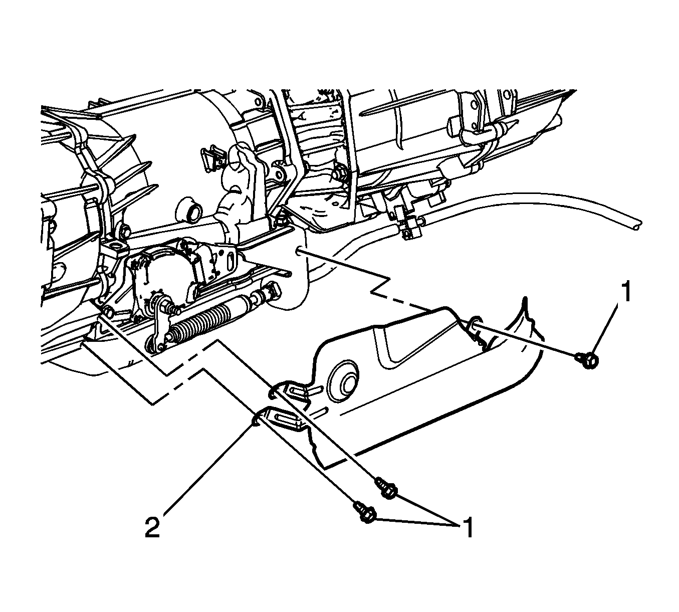
- Remove the right heat shield bolts (1).
- Remove the right heat shield (2).
- Remove the left heat shield bolts (1).
- Remove the left heat shield (2).
- Disconnect the range selector cable end (3) from the range selector lever.
- Remove the retainer (1) from the range selector cable (2).
- Push the range selector cable locking tabs (2) inward toward each other to release the cable from the bracket.
- Disconnect the transmission main electrical connector (3).
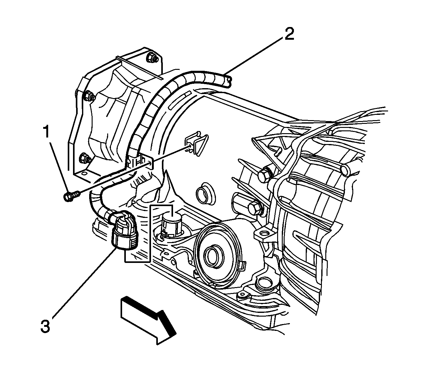
- Remove the screw (1) securing the engine wiring harness (2) to the right side of the transmission, and position the harness over the transmission.
- Disconnect the park/neutral back up switch electrical connector (3).
- Remove the screw (2) securing the engine wiring harness (1) to the left side of the transmission, and position the wiring harness aside.
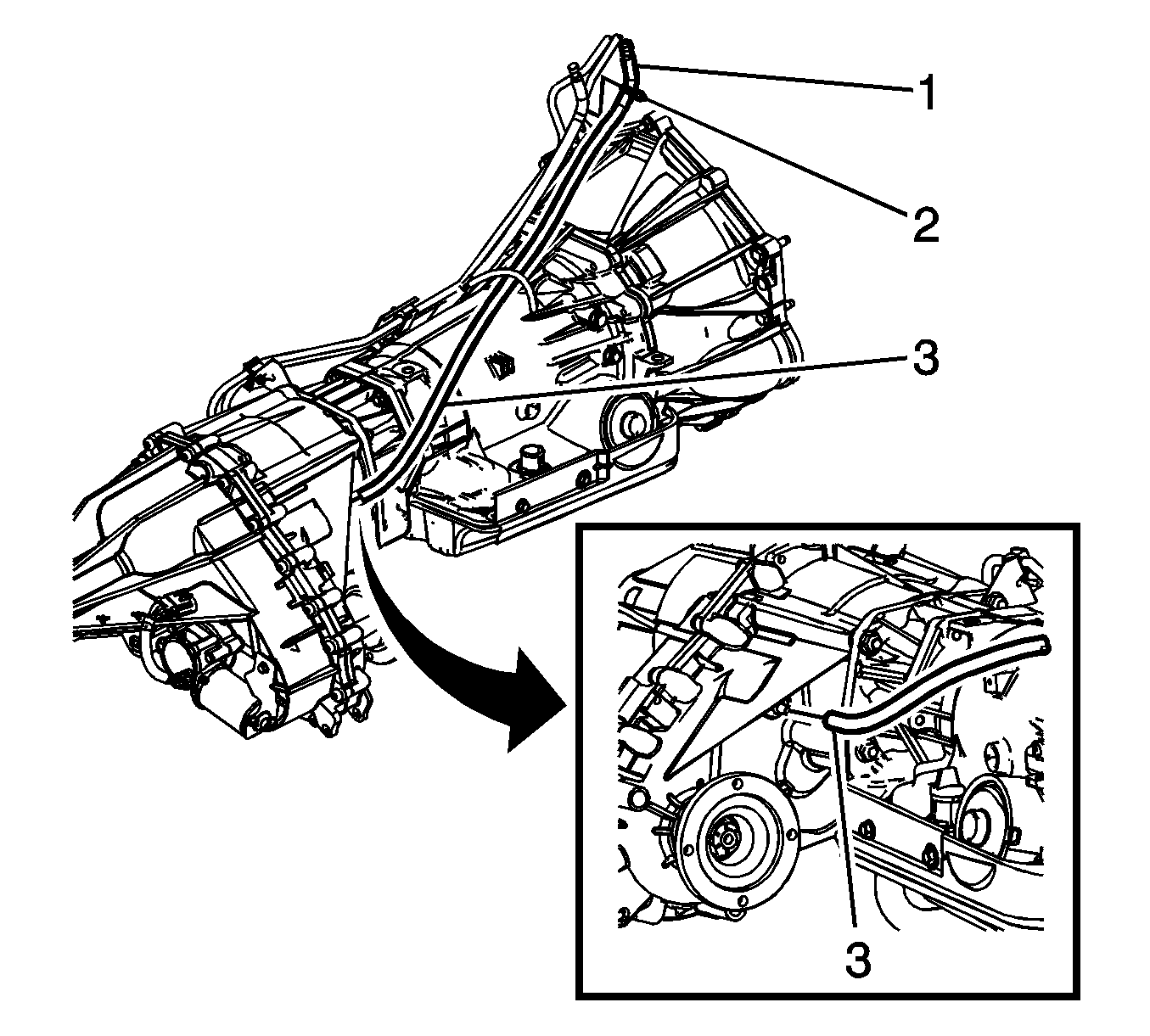
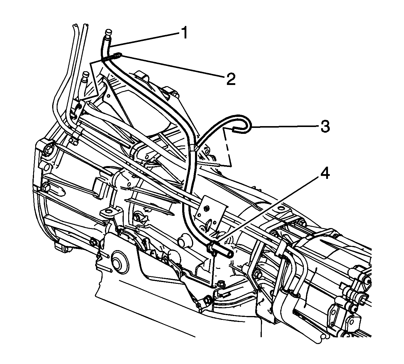
- Disconnect the transfer case vent hose retainer (2) from the fuel hose/pipe bracket.
- Disconnect the transmission vent hose retainer (2) from the fuel hose/pipe bracket.
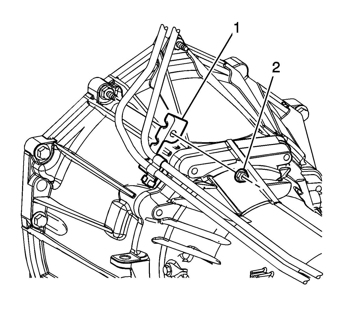
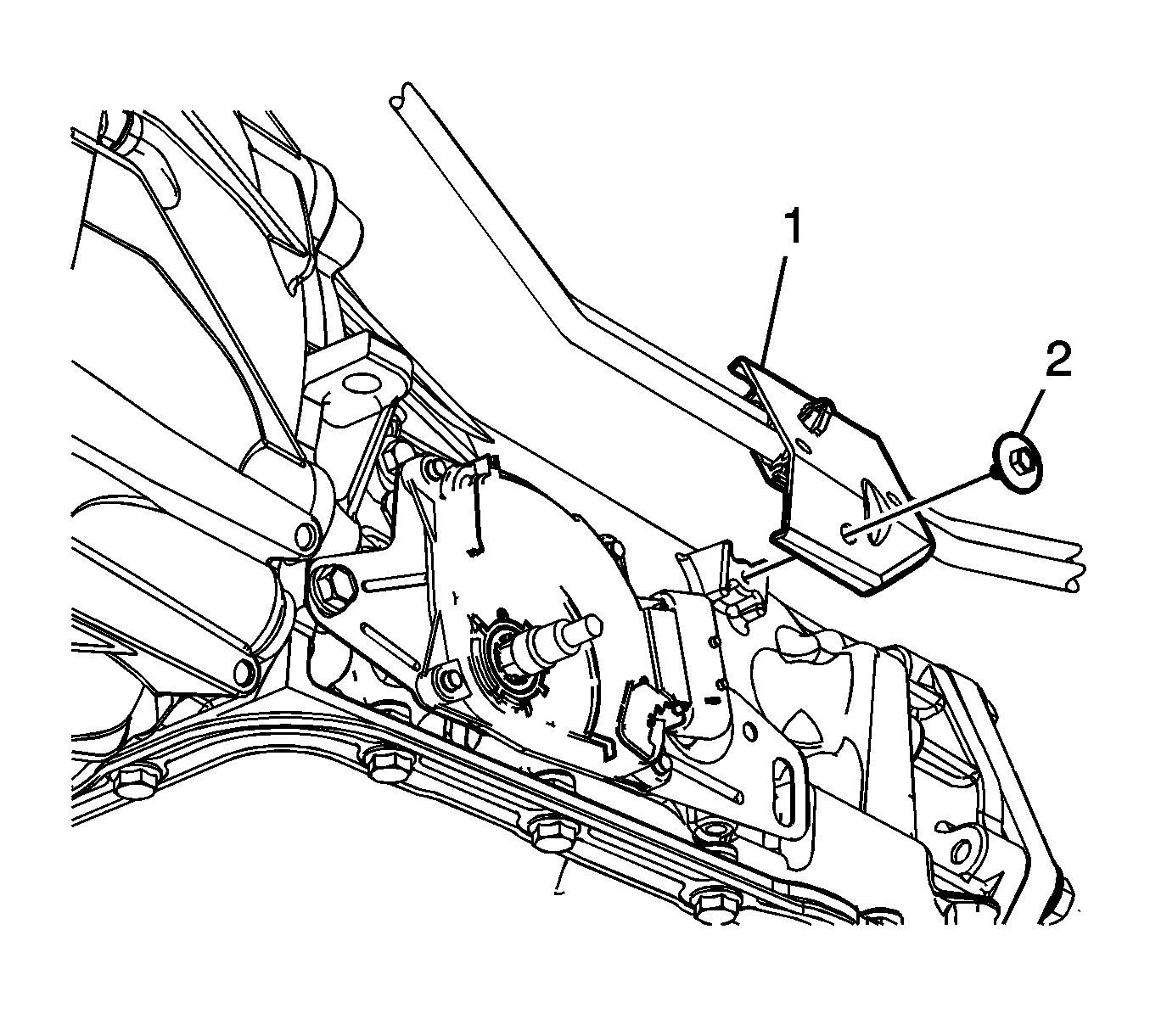
- Remove the nut (2) securing the fuel hose/pipe bracket (1) to the transmission.
- Remove the screw (2) securing the fuel hose/pipe bracket (1) to the transmission.
- Disconnect the fuel hose/pipe retainer (1) from the bracket on the transfer case adaptor, and position aside the fuel hose/pipe bundle.
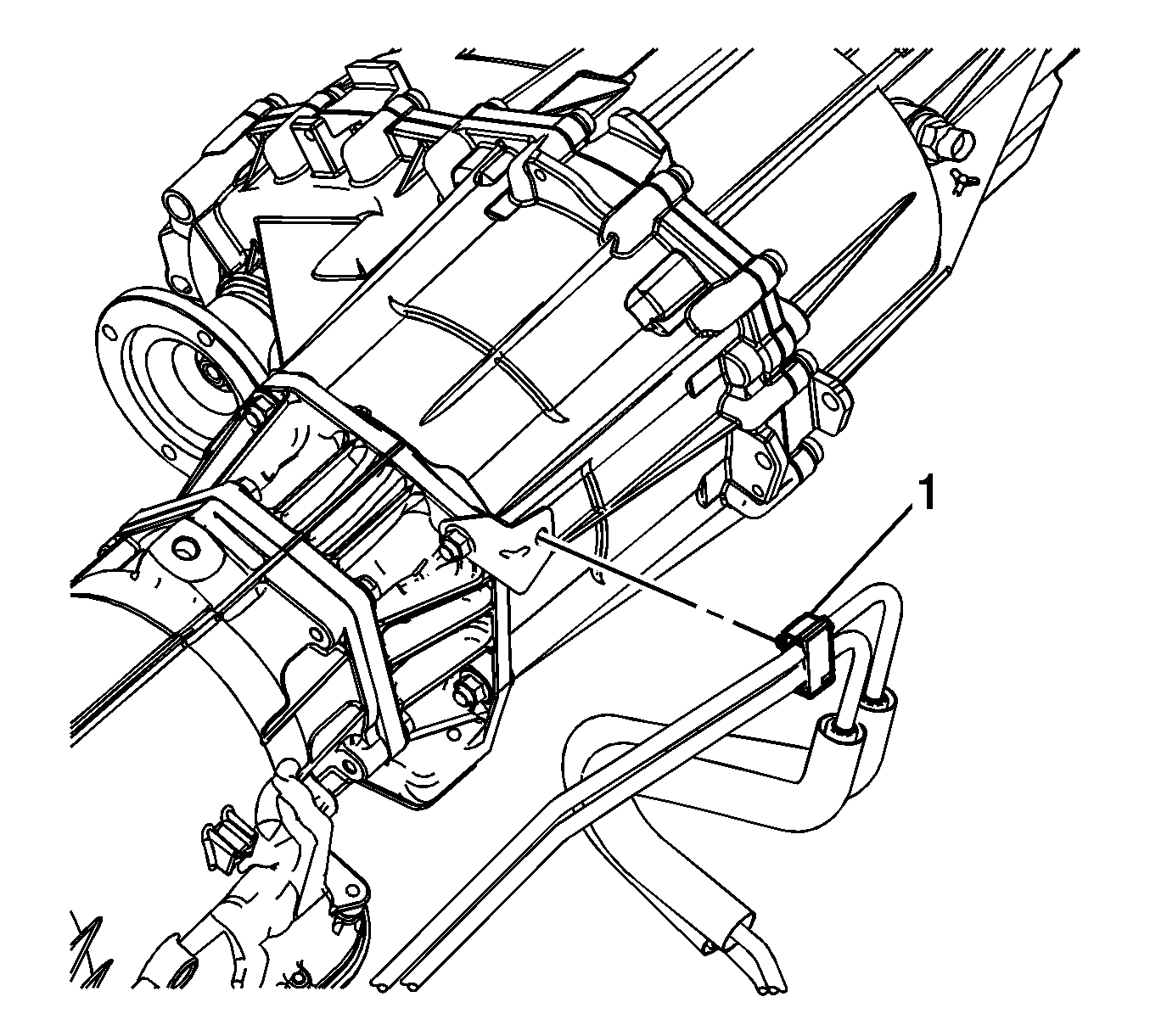
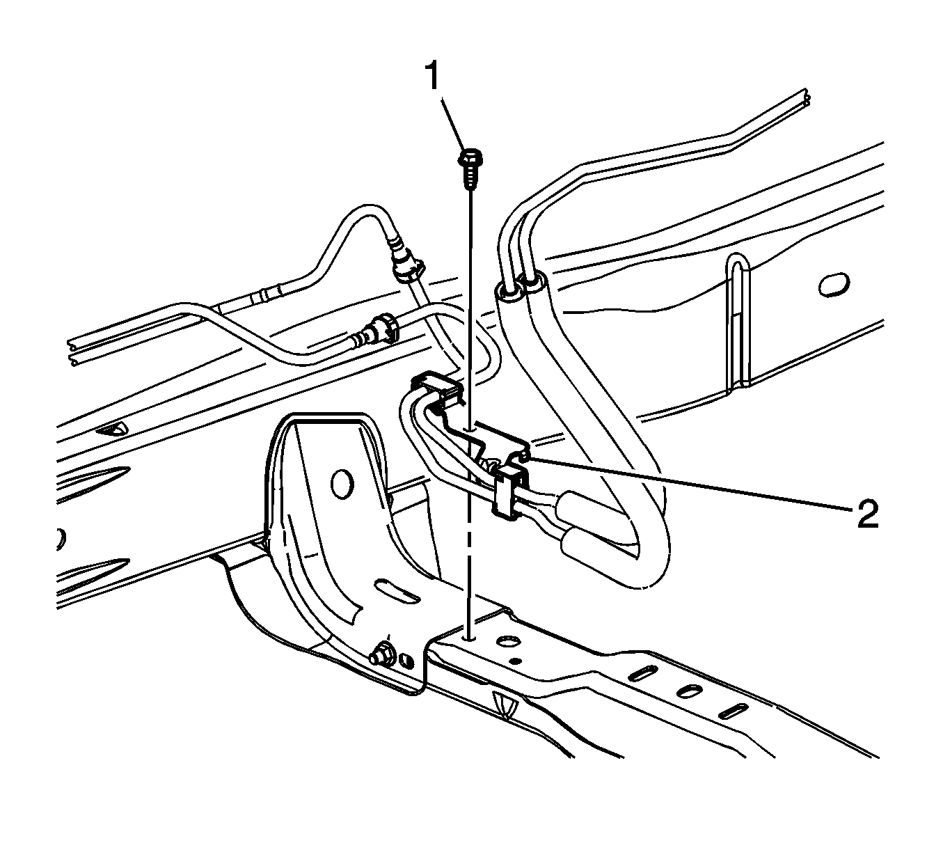
- Remove the bolt (1) securing the fuel hose/pipe bracket (2) to the transmission crossmember.
- Remove the inspection plug (3) from the transmission (1).
- Mark the torque converter to flexplate/flywheel orientation to ensure proper realignment.
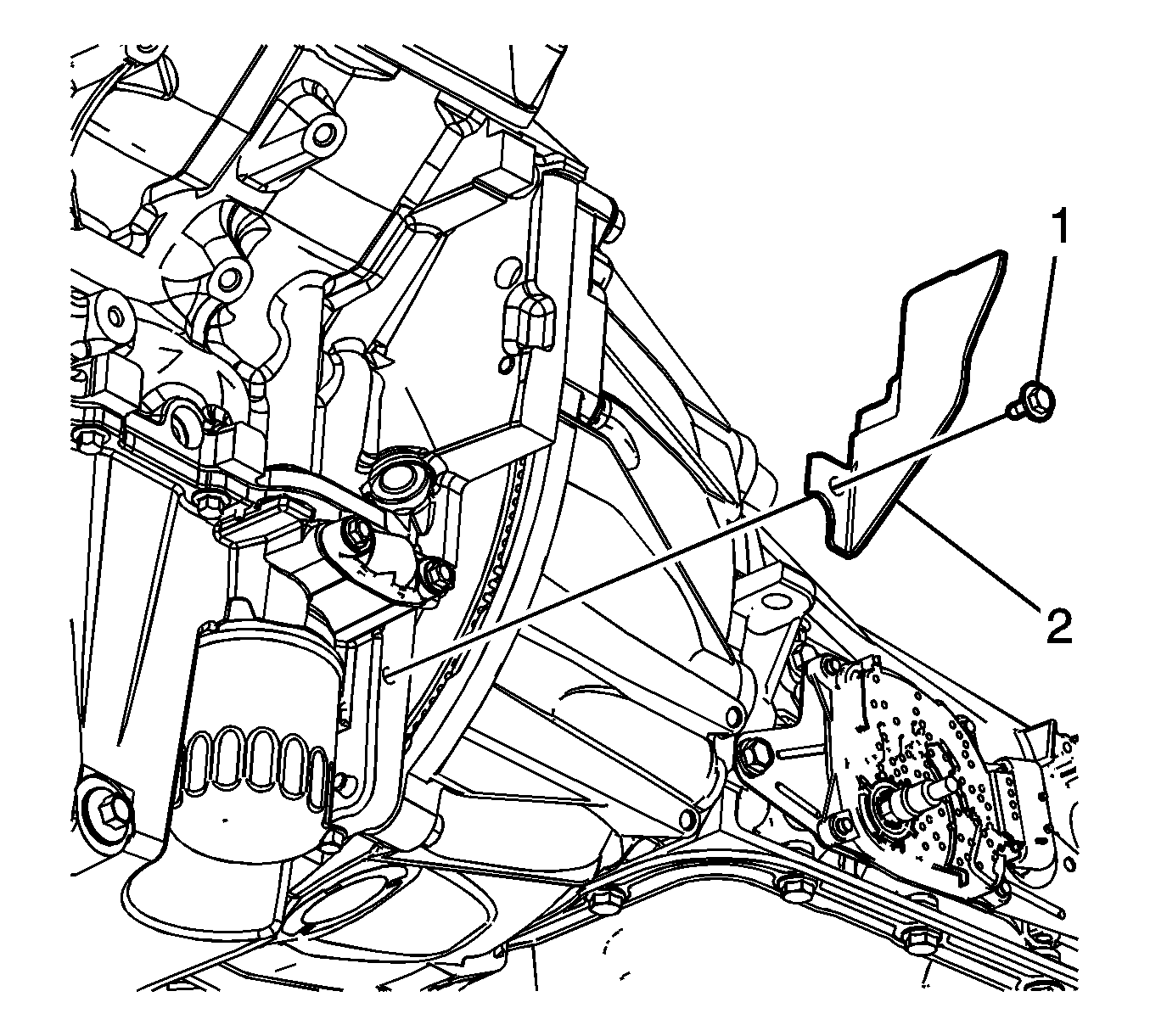
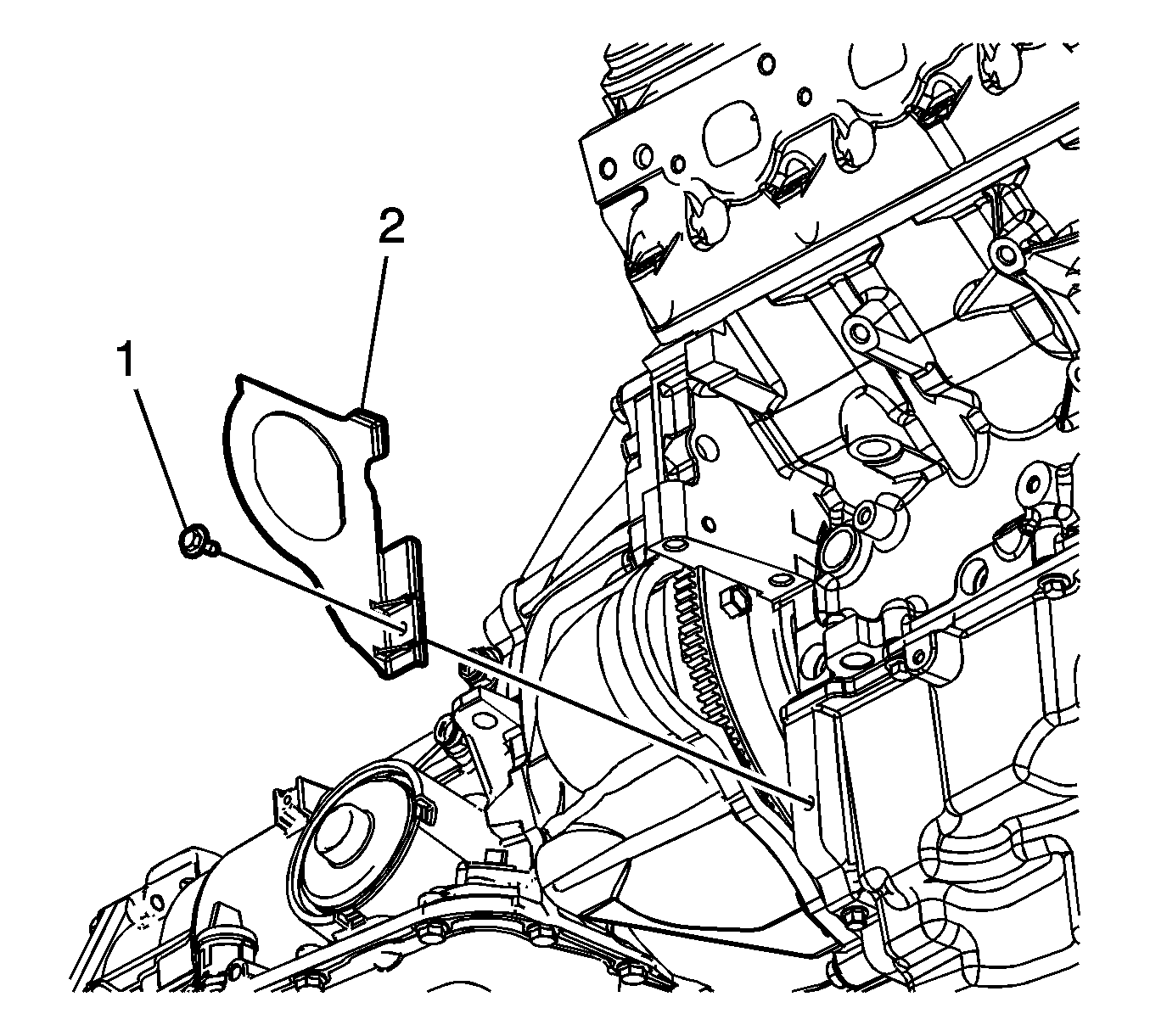
- Remove the left flywheel inspection cover bolt (1).
- Remove the left flywheel inspection cover (2).
- Remove the starter motor. Refer to Starter Replacement.
- Remove the right flywheel inspection cover bolt (1).
- Remove the right flywheel inspection cover (2).
- Remove the engine protection shield. Refer to Engine Protection Shield Replacement.
- Repeat the following steps for all torque converter bolts (1):
- Place an oil pan under the transmission fluid cooler pipes.
- Disconnect the transmission oil cooler pipes from the transmission ONLY. Refer to Transmission Fluid Cooler Hose/Pipe Replacement.
- Plug the open outlet ports to prevent fluid loss and contamination.
- Drain the transmission fluid if necessary. Refer to Automatic Transmission Fluid and Filter Replacement.
- Support and secure the transmission using a suitable transmission jack.
- Remove the transmission crossmember. Refer to Transmission Support Crossmember Replacement.
- Remove the transfer case assembly. Refer to Transfer Case Assembly Replacement.
- Remove the 2 transmission mounting studs (1).
- Remove the 6 transmission mounting bolts (2, 3).
- Separate the transmission from the engine alignment dowels.
- Using the transmission jack, carefully lower the transmission from the vehicle.
- Install the J 21366 onto the transmission bell housing to retain the torque converter.
- Perform the flush and flow test on the automatic transmission oil cooler. Refer to Transmission Fluid Cooler Flushing and Flow Test.
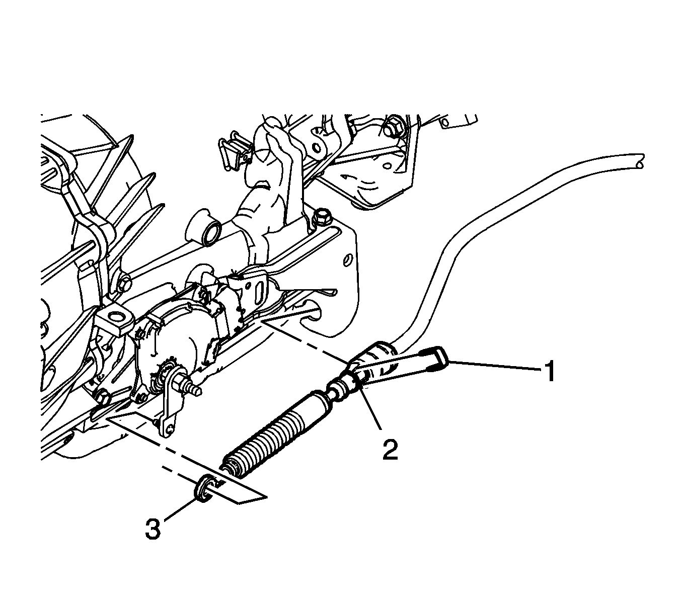
Note: Do not pull on the boot portion of the cable.


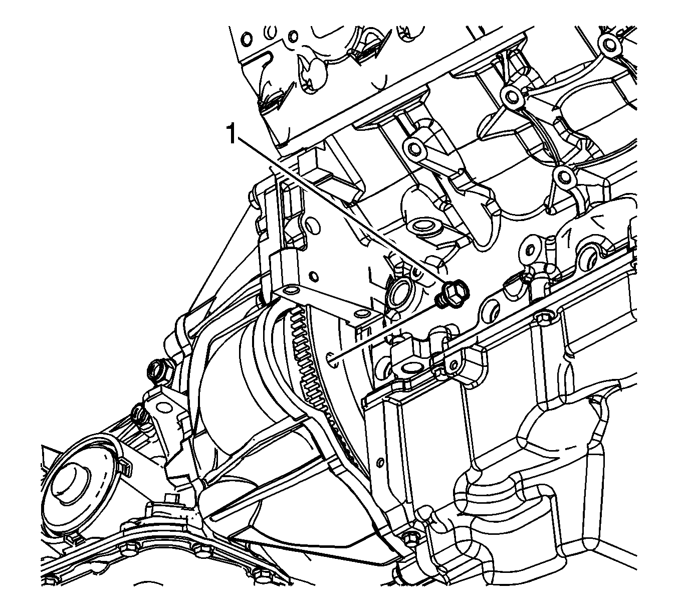
| • | Rotate the harmonic balancer center bolt clockwise ONLY, in order to access the torque converter bolt. |
| • | Remove the torque converter bolt: |
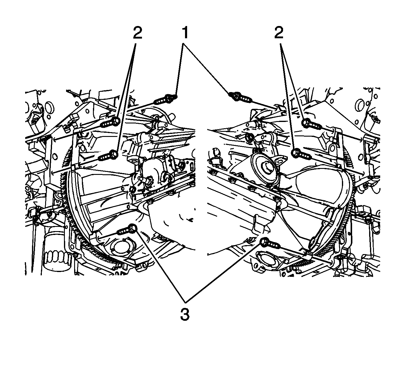
Note: Ensure clearance is maintained between the transmission and the following:
• The engine wiring harness • The fuel hose/pipe brackets • The transmission oil cooler pipes

Installation Procedure
- Remove the J 21366 from the transmission.
- Ensure the torque converter is fully engaged with the transmission oil pump.
- Using the transmission jack, carefully raise the transmission to the engine.
- Align the transmission with the engine alignment dowels.
- Install the 6 transmission mounting bolts (2, 3).
- Install the 2 transmission mounting studs (1).
- Install the transfer case assembly. Refer to Transfer Case Assembly Replacement.
- Install the transmission crossmember. Refer to Transmission Support Crossmember Replacement.
- Remove the transmission jack from under the vehicle.
- Connect the transmission oil cooler pipes to the transmission. Refer to Transmission Fluid Cooler Hose/Pipe Replacement.
- Align the torque converter to flexplate/flywheel orientation marks made during the removal procedure.
- Repeat the following steps for all 3 torque converter bolts (1):
- Install the engine protection shield. Refer to Engine Protection Shield Replacement.
- Install the right flywheel inspection cover (2).
- Install the right flywheel inspection cover bolt (1).
- Install the starter motor. Refer to Starter Replacement.
- Install the left flywheel inspection cover (2).
- Install the left flywheel inspection cover bolt (1).
- Install the inspection plug (3) to the transmission (1).
- Install the bolt (1) securing the fuel hose/pipe bracket (2) to the transmission crossmember.
- Attach the fuel hose/pipe retainer (1) to the bracket on the transfer case adaptor.
- Install the screw (2) securing the fuel hose/pipe bracket (1) to the transmission.
- Install the nut (2) securing the fuel hose/pipe bracket (1) to the transmission.
- Connect the transmission vent hose retainer (2) to the fuel hose/pipe bracket.
- Connect the transfer case vent hose retainer (2) to the fuel hose/pipe bracket.
- Connect the park/neutral back up switch electrical connector (3).
- Install the screw (2) securing the engine wiring harness (1) to the left side of the transmission.
- Connect the transmission main electrical connector (3).
- Install the screw (1) securing the engine wiring harness (2) to the right side of the transmission.
- Install the range selector cable (2) to the range selector cable bracket. Ensure the range selector cable retaining tabs fully engage the range selector cable bracket.
- Install the retainer (1) to the range selector cable (2).
- Connect the range selector cable end (3) to the transaxle range switch lever.
- Install the left heat shield (2).
- Install the left heat shield bolts (1).
- Install the right heat shield (2).
- Install the right heat shield bolts (1).
- Install the right and left catalytic converters. Refer to Catalytic Converter Replacement - Right Side and Catalytic Converter Replacement - Left Side.
- Install the filler tube. Refer to Transmission Fluid Filler Tube and Seal Replacement.
- Fill the transmission fluid if necessary. Refer to Automatic Transmission Fluid and Filter Replacement.
- Adjust the automatic transmission range selector cable. Refer to Range Selector Lever Cable Adjustment.
- Lower the vehicle.

Note: Ensure clearance is maintained between the transmission and the following:
• The engine wiring harness • The fuel hose/pipe brackets • The transmission oil cooler pipes

Caution: Refer to Fastener Caution in the Preface section.
Note: Ensure the torque converter turns freely while tightening the transmission mounting bolts.
Tighten
Tighten the bolts to 50 N·m (37 lb ft).
Tighten
Tighten the studs to 50 N·m (37 lb ft).

| 12.1. | Rotate the harmonic balancer center bolt clockwise ONLY, in order to access the torque converter bolt holes. |
| 12.2. | To aid in alignment of the torque converter to the flexplate/flywheel. Install all 3 torque converter bolts before fully tightening using one of the following: |
Tighten
Tighten the torque converter bolts to 60 N·m (44 lb ft).

Tighten
Tighten the bolt to 10 N·m (89 lb in).

Tighten
Tighten the bolt to 10 N·m (89 lb in).


Tighten
Tighten the bolt to 20 N·m (15 lb ft).


Tighten
Tighten the screw to 9 N·m (80 lb in).

Tighten
Tighten the nut to 20 N·m (15 lb ft).


Tighten
Tighten the screw to 9 N·m (80 lb in).

Tighten
Tighten the screw to 9 N·m (80 lb in).

Note: Ensure the range selector cable is routed exactly as originally positioned in the vehicle to avoid coming into contact with potential hazards such as hot, sharp, and moving objects.

Tighten
Tighten the bolts to 10 N·m (89 lb in).

Tighten
Tighten the bolts to 10 N·m (89 lb in).
Transmission Final Test and Inspection
Complete the following procedure after the transmission is installed in the vehicle:
- With the ignition OFF or disconnected, crank the engine several times. Listen for any unusual noises or evidence that any parts are binding.
- Place transmission in neutral, start the engine and listen for any unusual noises or evidence that any parts are binding.
- While the engine continues to idle raise and support the vehicle. Refer to Lifting and Jacking the Vehicle.
- Perform a final inspection for the proper fluid level. Refer to Transmission Fluid Check.
- Lower the vehicle.
- Reset the TAP values. Refer to Transmission Adaptive Functions.
- Road test the vehicle.
Note: It is recommended that transmission adaptive pressure (TAP) information be reset.
Resetting the TAP values using a scan tool will erase all learned values in all cells. As a result, The ECM, PCM or TCM will need to relearn TAP values. Transmission performance may be affected as new TAP values are learned.Transmission Replacement 2WD 5.3L
Special Tools
J 21366 Converter Holding Strap
Removal Procedure
- Ensure the vehicle is in the park position.
- Remove the filler tube. Refer to Transmission Fluid Filler Tube and Seal Replacement.
- Remove the right and left catalytic converters. Refer to Catalytic Converter Replacement - Right Side and Catalytic Converter Replacement - Left Side.
- Remove the right heat shield bolts (1).
- Remove the right heat shield (2).
- Remove the left heat shield bolts (1).
- Remove the left heat shield (2).
- Disconnect the range selector cable end (3) from the range selector lever.
- Remove the retainer (1) from the range selector cable (2).
- Push the range selector cable locking tabs (2) inward toward each other to release the cable from the bracket.
- Disconnect the following engine wiring harness electrical connectors:
- Remove the screw (4) securing the engine wiring harness (3) to the right side of the transmission, and position the harness over the transmission.
- Disconnect the park/neutral back up switch electrical connector (3).
- Remove the screw (2) securing the engine wiring harness (1) to the left side of the transmission, and position the wiring harness aside.
- Remove the nut (2) securing the fuel hose/pipe bracket (1) to the transmission.
- Remove the screw (5) securing the fuel hose/pipe bracket (4) to the transmission.
- Remove the nut (2) securing the fuel hose/pipe bracket (1) to the transmission.
- Remove the bolt (1) securing the fuel hose/pipe bracket (2) to the transmission crossmember.
- Remove the inspection plug (3) from the transmission (1).
- Mark the torque converter to flexplate/flywheel orientation to ensure proper realignment.
- Remove the left flywheel inspection cover bolt (1).
- Remove the left flywheel inspection cover (2).
- Remove the starter motor. Refer to Starter Motor Replacement.
- Remove the right flywheel inspection cover bolt (1).
- Remove the right flywheel inspection cover (2).
- Remove the engine protection shield. Refer to Engine Protection Shield Replacement.
- Repeat the following steps for all torque converter bolts:
- Place an oil pan under the transmission fluid cooler pipes.
- Disconnect the transmission oil cooler pipes from the transmission ONLY. Refer to Transmission Fluid Cooler Hose/Pipe Replacement.
- Plug the open outlet ports to prevent fluid loss and contamination.
- Drain the transmission fluid if necessary. Refer to Automatic Transmission Fluid and Filter Replacement.
- Support and secure the transmission using a suitable transmission jack.
- Remove the transmission crossmember. Refer to Transmission Support Crossmember Replacement.
- Remove the transfer case assembly. Refer to Transfer Case Assembly Replacement.
- Remove the 2 transmission mounting studs (1).
- Remove the 6 transmission mounting bolts (2, 3).
- Separate the transmission from the engine alignment dowels.
- Using the transmission jack, carefully lower the transmission from the vehicle.
- Install the J 21366 onto the transmission bell housing to retain the torque converter.
- Perform the flush and flow test on the automatic transmission oil cooler. Refer to Transmission Fluid Cooler Flushing and Flow Test.

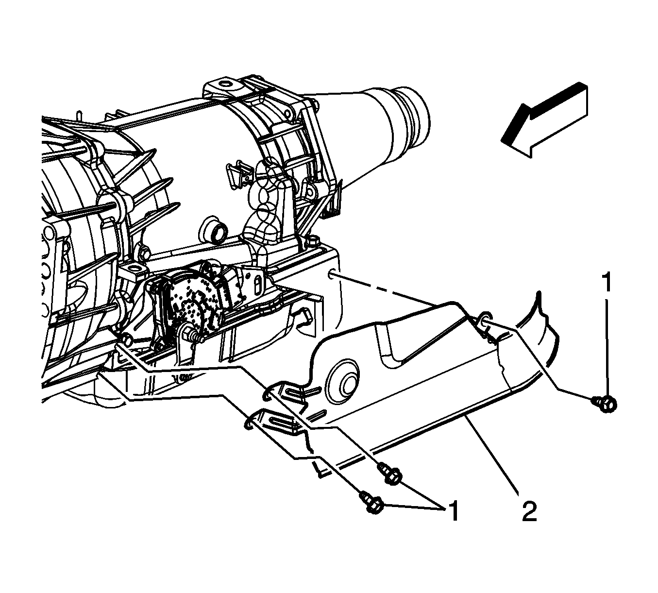

Note: Do not pull on the boot portion of the cable.

| • | The heated oxygen sensor (6) |
| • | The transmission main connector (5) |
| • | The vehicle speed sensor (VSS) (1) |


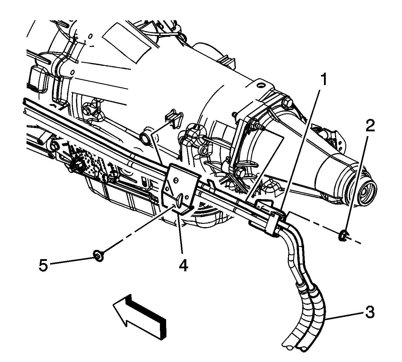


| • | Rotate the harmonic balancer center bolt clockwise ONLY, in order to access the torque converter bolt. |
| • | Remove the torque converter bolt: |

Note: Ensure clearance is maintained between the transmission and the following:
• The engine wiring harness • The fuel hose/pipe brackets • The transmission oil cooler pipes

Installation Procedure
- Remove the J 21366 from the transmission.
- Ensure the torque converter is fully engaged with the transmission oil pump.
- Using the transmission jack, carefully raise the transmission to the engine.
- Align the transmission with the engine alignment dowels.
- Install the 6 transmission mounting bolts (2, 3).
- Install the 2 transmission mounting studs (1).
- Install the transfer case assembly. Refer to Transfer Case Assembly Replacement.
- Install the transmission crossmember. Refer to Transmission Support Crossmember Replacement.
- Remove the transmission jack from under the vehicle.
- Connect the transmission oil cooler pipes to the transmission. Refer to Transmission Fluid Cooler Hose/Pipe Replacement.
- Align the torque converter to flexplate/flywheel orientation marks made during the removal procedure.
- Repeat the following steps for all 3 torque converter bolts:
- Install the engine protection shield. Refer to Engine Protection Shield Replacement.
- Install the right flywheel inspection cover (2).
- Install the right flywheel inspection cover bolt (1).
- Install the starter motor. Refer to Starter Motor Replacement.
- Install the left flywheel inspection cover (2).
- Install the left flywheel inspection cover bolt (1).
- Install the inspection plug (3) to the transmission (1).
- Install the bolt (1) securing the fuel hose/pipe bracket (2) to the transmission crossmember.
- Install the nut (2) securing the fuel hose/pipe bracket (1) to the transmission.
- Install the screw (5) securing the fuel hose/pipe bracket (4) to the transmission.
- Install the nut (2) securing the fuel hose/pipe bracket (1) to the transmission.
- Connect the park/neutral back up switch electrical connector (3).
- Install the screw (2) securing the engine wiring harness (1) to the left side of the transmission.
- Connect the following engine wiring harness electrical connectors:
- Install the screw (4) securing the engine wiring harness (3) to the right side of the transmission.
- Install the range selector cable (2) to the range selector cable bracket. Ensure the range selector cable retaining tabs fully engage the range selector cable bracket.
- Install the retainer (1) to the range selector cable (2).
- Connect the range selector cable end (3) to the transaxle range switch lever.
- Install the left heat shield (2).
- Install the left heat shield bolts (1).
- Install the right heat shield (2).
- Install the right heat shield bolts (1).
- Install the right and left catalytic converters. Refer to Catalytic Converter Replacement - Right Side and Catalytic Converter Replacement - Left Side.
- Install the filler tube. Refer to Transmission Fluid Filler Tube and Seal Replacement.
- Fill the transmission fluid if necessary. Refer to Automatic Transmission Fluid and Filter Replacement.
- Adjust the automatic transmission range selector cable. Refer to Range Selector Lever Cable Adjustment.
- Lower the vehicle.

Note: Ensure clearance is maintained between the transmission and the following:
• The engine wiring harness • The fuel hose/pipe brackets • The transmission oil cooler pipes

Caution: Refer to Fastener Caution in the Preface section.
Note: Ensure the torque converter turns freely while tightening the transmission mounting bolts.
Tighten
Tighten the bolts to 50 N·m (37 lb ft).
Tighten
Tighten the studs to 50 N·m (37 lb ft).

| 12.1. | Rotate the harmonic balancer center bolt clockwise ONLY, in order to access the torque converter bolt holes. |
| 12.2. | To aid in alignment of the torque converter to the flexplate/flywheel. Install all 3 torque converter bolts before fully tightening using one of the following: |
Tighten
Tighten the torque converter bolts to 60 N·m (44 lb ft).

Tighten
Tighten the bolt to 10 N·m (89 lb in).

Tighten
Tighten the bolt to 10 N·m (89 lb in).


Tighten
Tighten the bolt to 20 N·m (15 lb ft).

Tighten
Tighten the nut to 20 N·m (15 lb ft).
Tighten
Tighten the screw to 9 N·m (80 lb in).

Tighten
Tighten the nut to 20 N·m (15 lb ft).

Tighten
Tighten the screw to 9 N·m (80 lb in).

| • | The heated oxygen sensor (6) |
| • | The transmission main connector (5) |
| • | The vehicle speed sensor (VSS) (1) |
Tighten
Tighten the screw to 9 N·m (80 lb in).
Note: Ensure the range selector cable is routed exactly as originally positioned in the vehicle to avoid coming into contact with potential hazards such as hot, sharp, and moving objects.


Tighten
Tighten the bolts to 10 N·m (89 lb in).

Tighten
Tighten the bolts to 10 N·m (89 lb in).
Transmission Final Test and Inspection
Complete the following procedure after the transmission is installed in the vehicle:
- With the ignition OFF or disconnected, crank the engine several times. Listen for any unusual noises or evidence that any parts are binding.
- Place transmission in neutral, start the engine and listen for any unusual noises or evidence that any parts are binding.
- While the engine continues to idle raise and support the vehicle. Refer to Lifting and Jacking the Vehicle.
- Perform a final inspection for the proper fluid level. Refer to Transmission Fluid Check.
- Lower the vehicle.
- Reset the TAP values. Refer to Transmission Adaptive Functions.
- Road test the vehicle.
Note: It is recommended that transmission adaptive pressure (TAP) information be reset.
Resetting the TAP values using a scan tool will erase all learned values in all cells. As a result, The ECM, PCM or TCM will need to relearn TAP values. Transmission performance may be affected as new TAP values are learned.