For 1990-2009 cars only
Special Tools
| • | J 35910 Drive Axle Seal Clamp Plier |
| • | J 8059 Snap Ring Pliers |
Removal Procedure
- Place the driveshaft in a vise.
- Use a hand grinder to cut through the large retaining clamp (2) located at the D/O joint (1).
- Use a hand grinder to cut through the small retaining clamp (4) on the small end of the seal (3).
- Slide the seal (2) down the driveshaft bar and away from the D/O joint (1).
- Remove the D/O joint housing in the following manner:
- Collapse and remove the D/O ball retaining ring using a common hand tool (screwdriver).
- Pull the D/O joint housing from the driveshaft bar.
- Using J 8059 , spread the small retaining ring (1) located in the cage and inner race assembly (3).
- Remove the cage and the inner race assembly (1) from the driveshaft bar (2).
- Remove the balls.
- Remove the inner race from the cage.
- Thoroughly degrease all parts.
- Remove the seal and discard.
- Clean the driveshaft bar, Use a wire brush to remove any rust in the seal mounting areas (grooves).
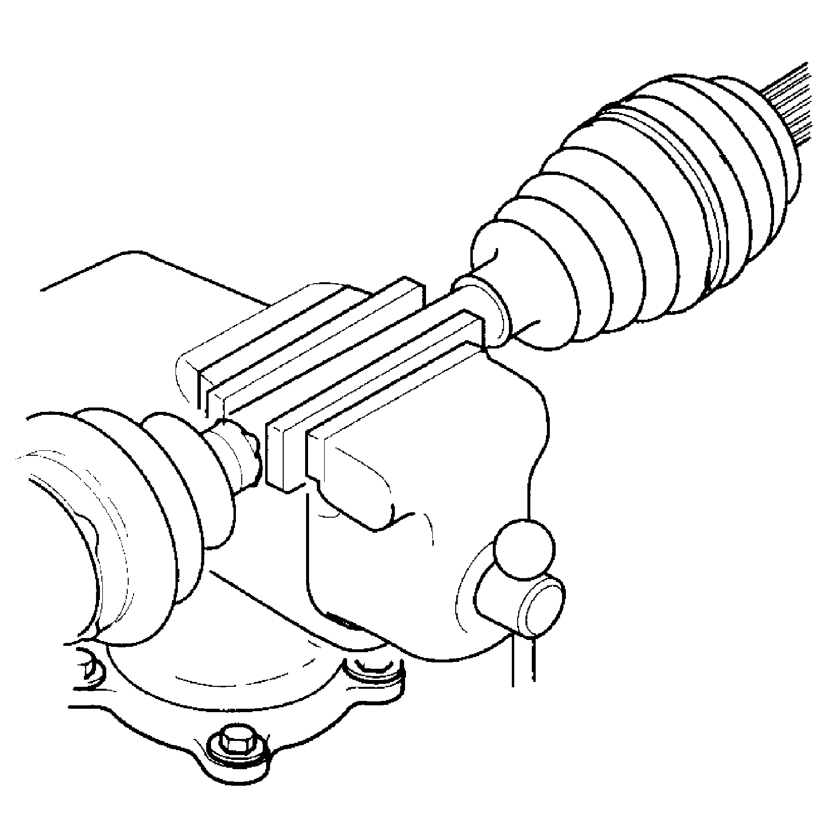
Note: Before placing the driveshaft in a vise, place protective covers over the vise jaws.
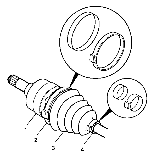
Note: Do not damage the D/O joint housing while using the hand grinder.
Discard the large retaining clamp.
Discard the small retaining clamp.
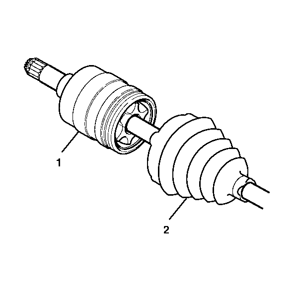
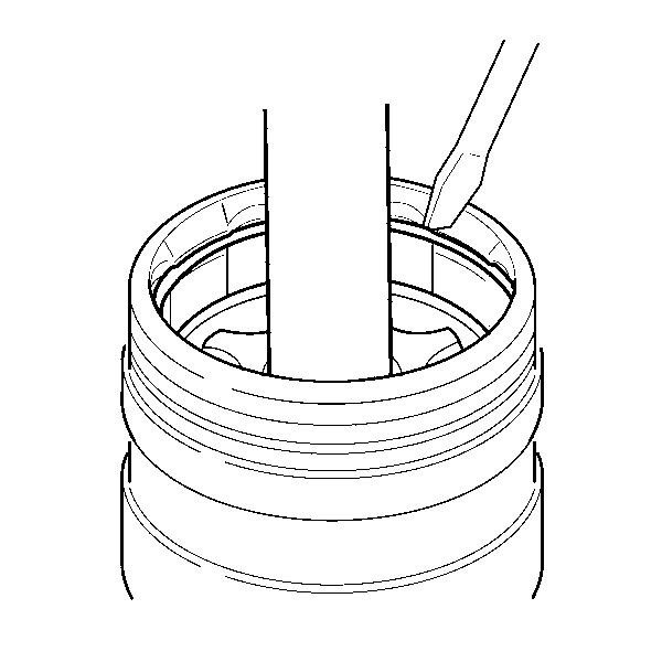
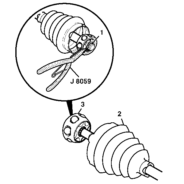
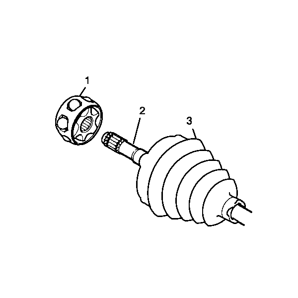
Check the D/O joint housing for unusual wear, cracks, or other damage. Replace the assembly if any damaged parts are evident.
Installation Procedure
- Install the new small retaining clamp (2) onto the neck of the seal (1).
- Slide the small retaining clamp and seal to their proper position on the driveshaft bar (3).
- Secure the small retaining clamp using J 35910 (or equivalent), a breaker bar, and a torque wrench.
- Place the cage on the table large diameter side up.
- Place the inner race (2) with retaining ring side up into the cage.
- Place the six balls (1) in the cage windows.
- Slide the cage/inner race assembly, small cage diameter first, onto the driveshaft bar.
- Install the small retaining ring (1) using J 8059 into the groove of the driveshaft bar.
- Pack the seal and D/O joint housing with the grease suppled in the kit. The amount of grease supplied in this kit has been pre-measured for this application.
- Place the new large retaining clamp on the seal.
- Slide the D/O joint housing over the cage and inner race assembly.
- Insert the D/O ball retaining ring into the groove at the top of the D/O joint housing.
- Install the seal onto the D/O joint housing.
- Check the inboard stroke position.
- Secure the new large retaining clamp and the seal to the D/O joint housing using J 35910 (or equivalent), a breaker bar, and a torque wrench.
- Fully stroke the D/O joint several times to disperse the grease.
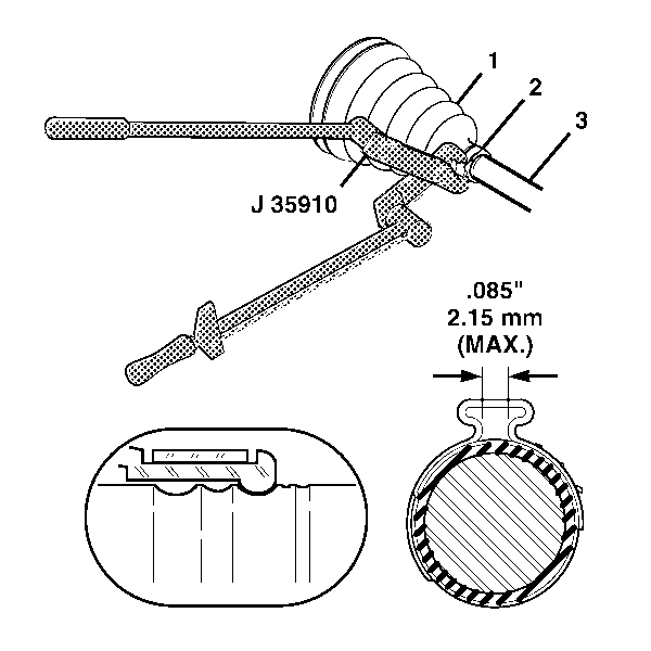
Caution: Refer to Fastener Caution in the Preface section.
Tighten the small retaining clamp (2) to 136 N·m (100 lb ft).
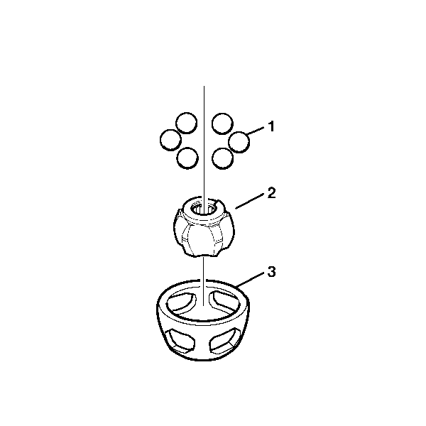
Note: The cage (3) is NOT symmetrical; the larger outside diameter is the bottom of the cage.

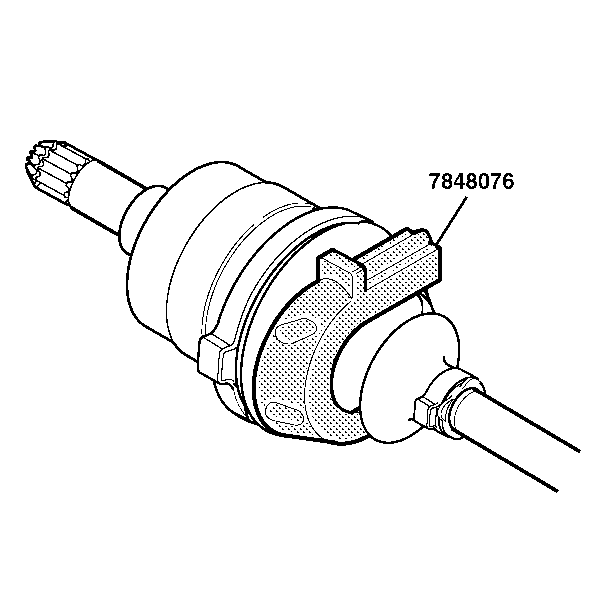


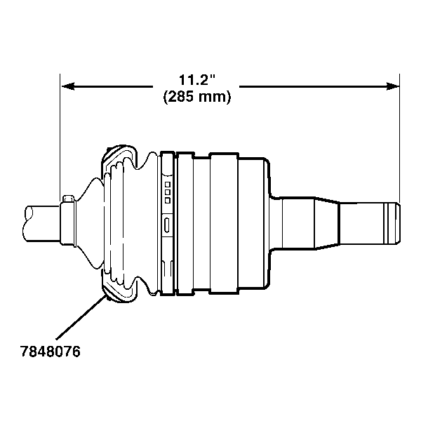
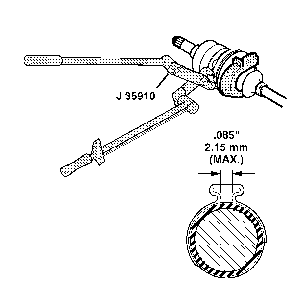
Tighten the large retaining clamp to 176 N·m (130 lb ft).
