For 1990-2009 cars only
Removal Procedure
- Relieve the fuel system pressure. Refer to Fuel Pressure Relief.
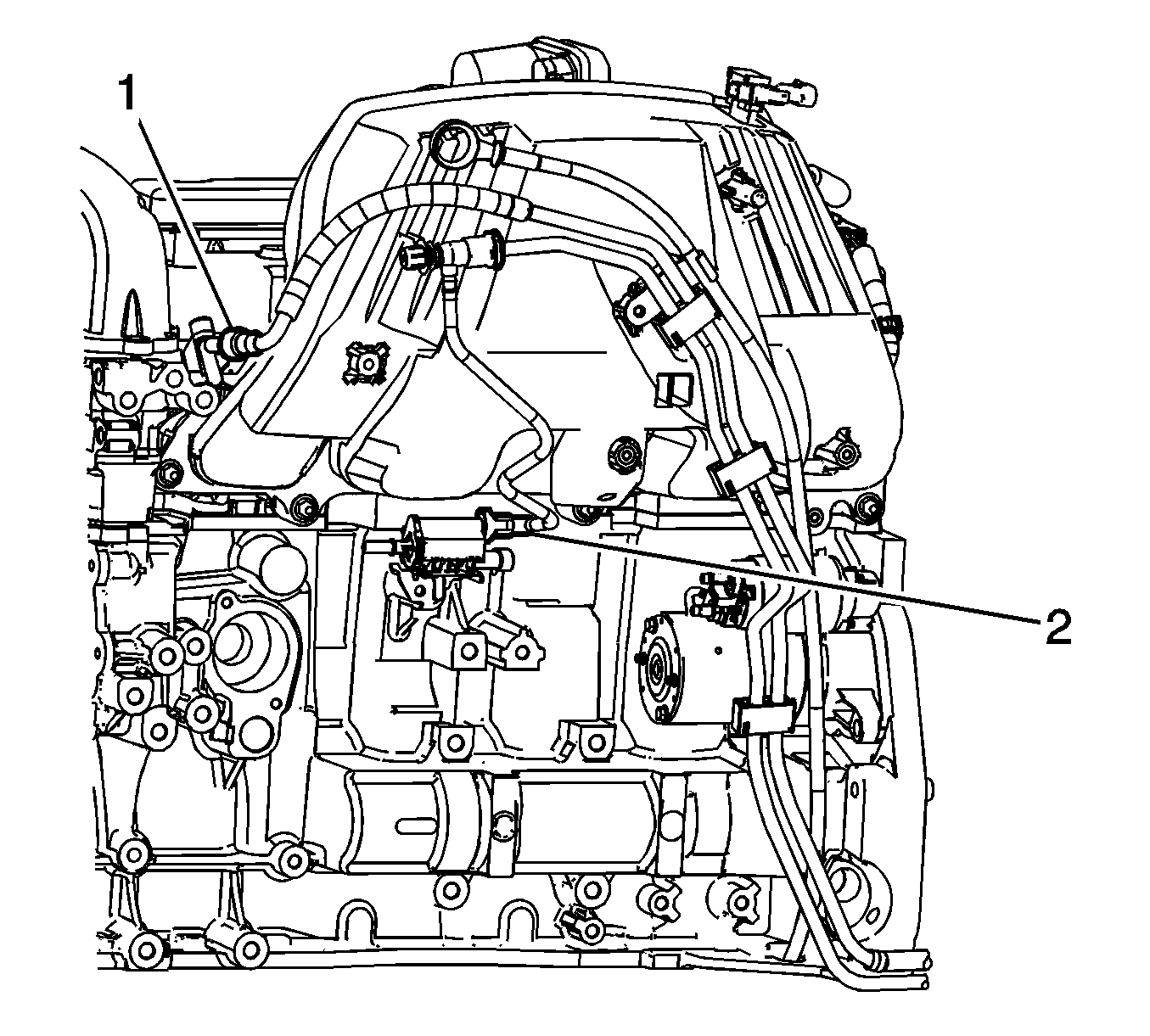
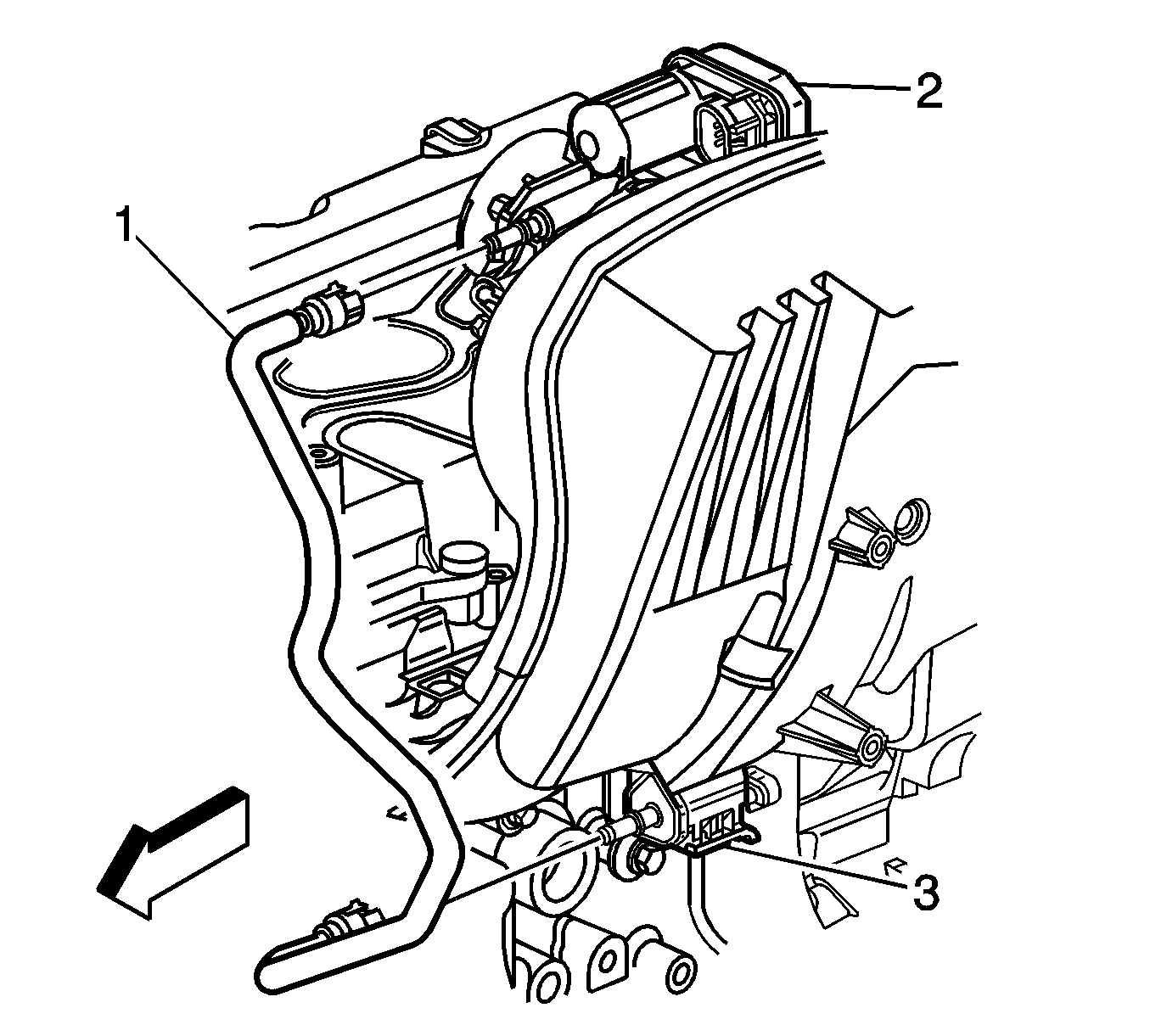
- Disconnect the fuel feed line quick connect fitting (1) from the fuel rail. Refer to Metal Collar Quick Connect Fitting Service.
- Disconnect the evaporative emission (EVAP) purge tube from the throttle body control module (2) and the EVAP canister purge solenoid valve (3). Refer to Plastic Collar Quick Connect Fitting Service.
- Remove the intake manifold. Refer to Intake Manifold Replacement.
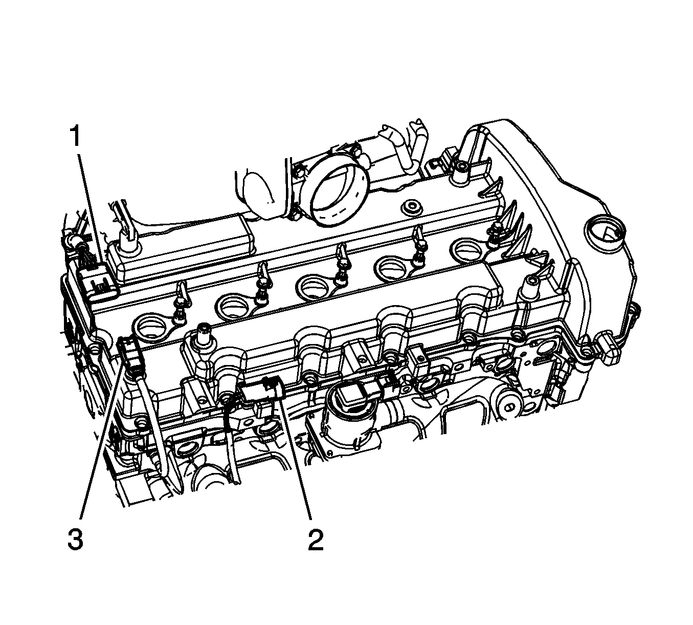
- Disconnect the engine wiring harness electrical connector (1) from the fuel injector harness electrical connector.
- Before removal, clean the fuel rail assembly and the cylinder head with a spray type engine cleaner, GM X-30A or equivalent, if necessary. Follow the package instructions. Do not soak the fuel rail in liquid cleaning solvent.
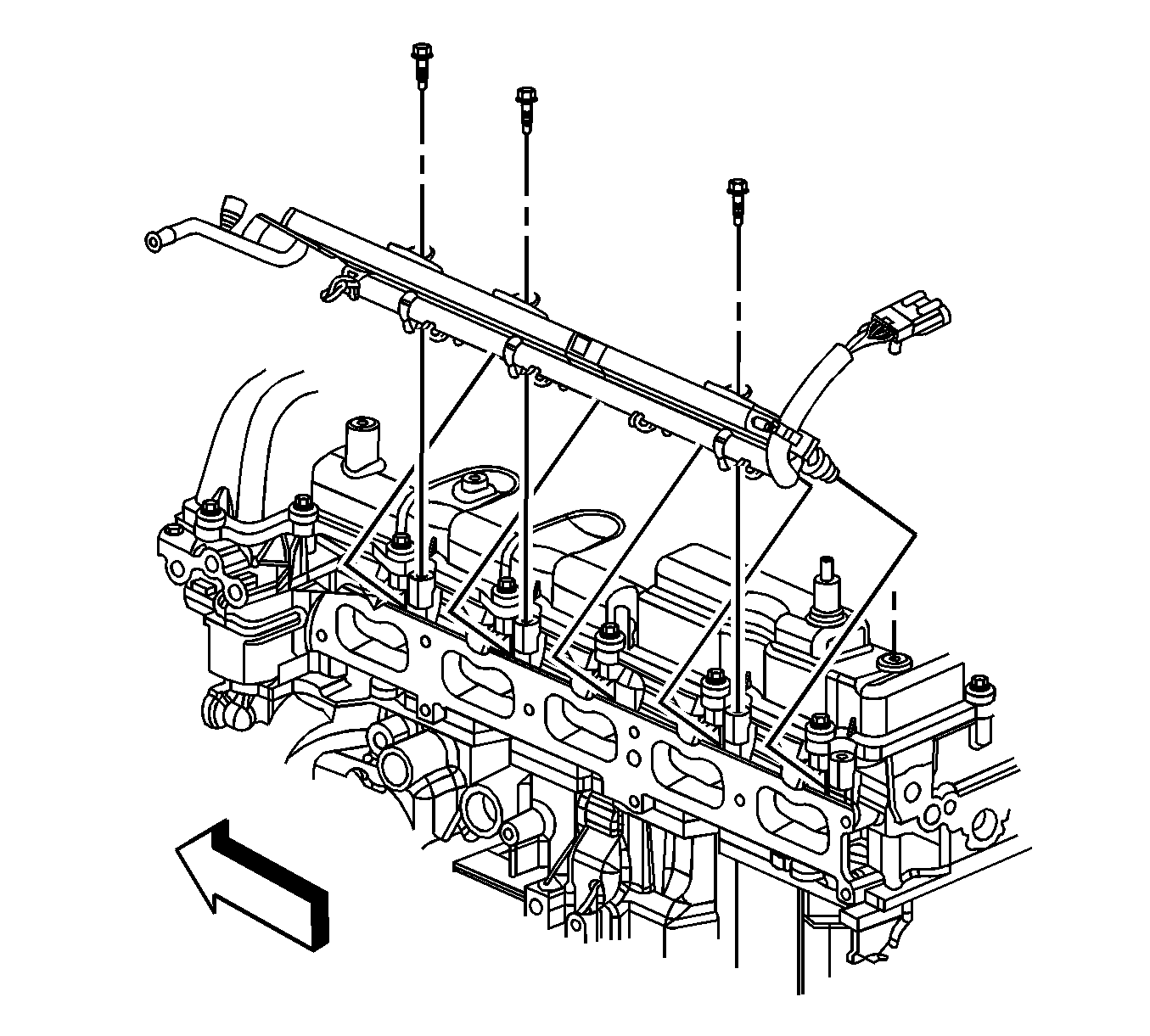
- Remove the fuel rail bolts.
- Remove the fuel rail from the cylinder head.
- Remove and discard the fuel injector lower O-ring seals from each fuel injector.
- If the fuel rail is not being replaced, proceed to the Installation Procedure.
Caution:
• Remove the fuel rail assembly carefully in order to prevent damage to the injector electrical connector terminals and the injector spray tips. Support the fuel rail after the fuel rail is removed in order to avoid damaging the fuel rail components. • Cap the fittings and plug the holes when servicing the fuel system in order to prevent dirt and other contaminants from entering open pipes and passages.
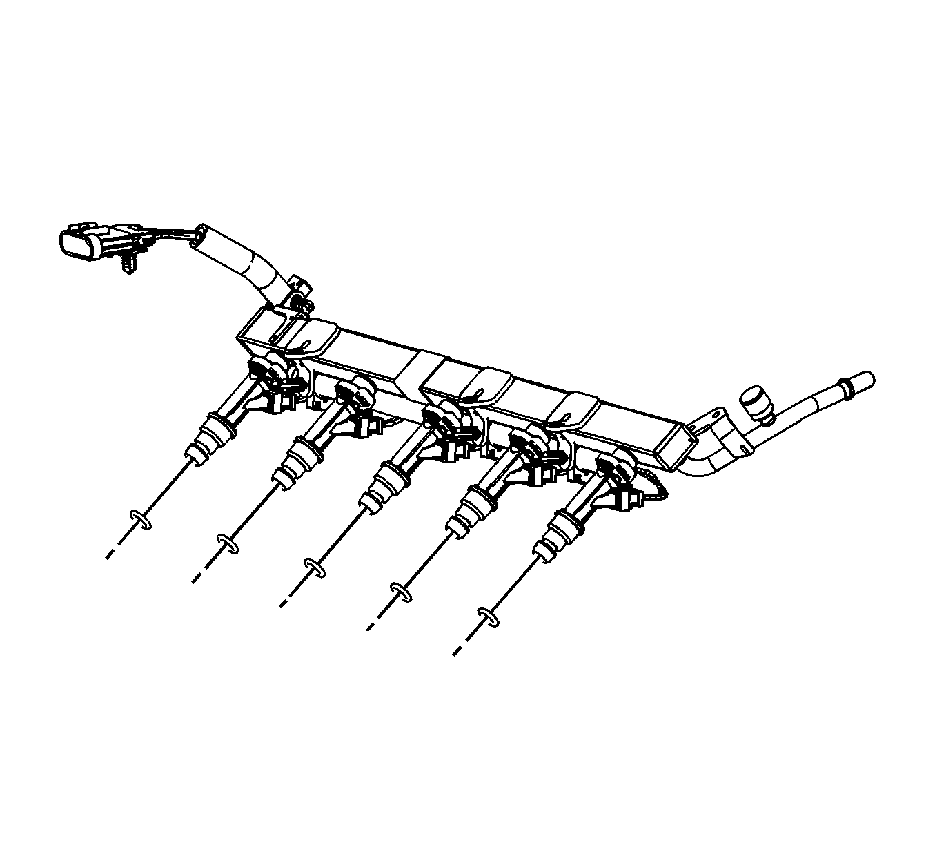
Disassembly Procedure
- Remove the fuel injector harness clips from the fuel rail and remove the harness (1).
- Remove the fuel injector retainers (2).
- Remove the fuel injectors (4).
- Remove the fuel injector upper O-ring seals (3) from the injectors.
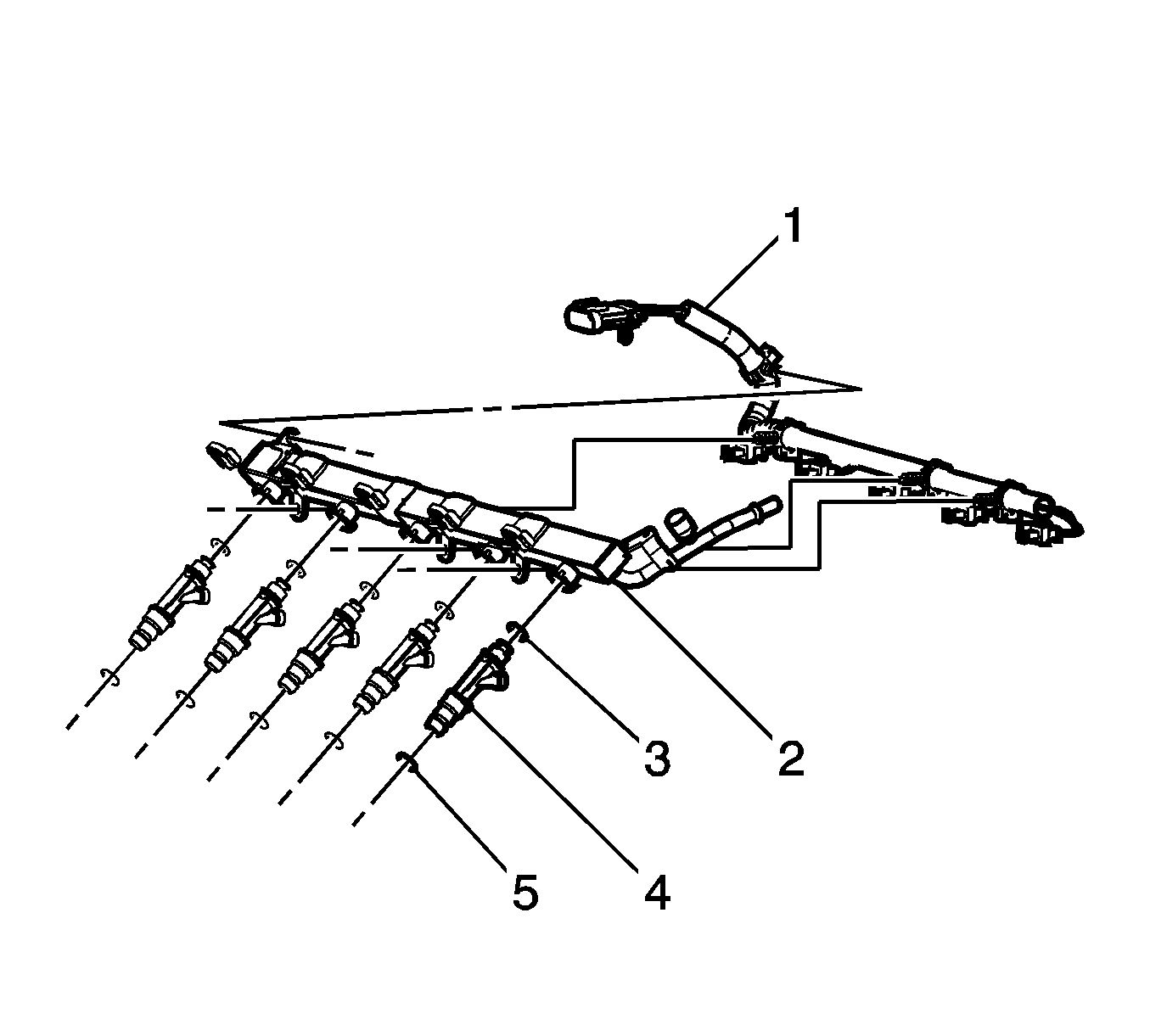
Assembly Procedure
- Lightly lubricate the NEW upper O-ring seals (3) with mineral oil GM P/N 9981704.
- Install the NEW upper O-ring seals (3) onto the fuel injectors.
- Install the fuel injectors (4).
- Install the fuel injector retainers (2).
- Position the harness (1) and install the fuel injector harness clips to the fuel rail.

Installation Procedure
- Lightly lubricate the NEW lower O-ring seals with mineral oil GM P/N 9981704.
- Install the NEW O-ring seals onto the tip of each injector.
- Position the fuel rail to the cylinder head, insert the spray tip ends of the fuel injectors into the cylinder head.
- Install the fuel rail bolts.
- Connect the engine wiring harness electrical connector (1) to the fuel injector harness electrical connector.
- Install the intake manifold. Refer to Intake Manifold Replacement.
- Connect the EVAP purge tube to the throttle body control module (2) and the EVAP canister purge solenoid valve (3). Refer to Plastic Collar Quick Connect Fitting Service.
- Connect the fuel feed line quick connect fitting (1) to the fuel rail. Refer to Metal Collar Quick Connect Fitting Service.
- Inspect for leaks.


Caution: Refer to Fastener Caution in the Preface section.
Tighten
Tighten the bolts to 10 N·m (89 lb in).


| 9.1. | Turn ON the ignition, with the engine OFF for 2 seconds. |
| 9.2. | Turn OFF the ignition for 10 seconds. |
| 9.3. | Turn ON the ignition, with the engine OFF. |
| 9.4. | Inspect for fuel leaks. |
