For 1990-2009 cars only
Removal Procedure
Caution: Refer to Fuel and Evaporative Emission Pipe Caution in the Preface section.
Caution: Refer to Gasoline/Gasoline Vapors Caution in the Preface section.
- Relieve the fuel pressure. Refer to Fuel Pressure Relief .
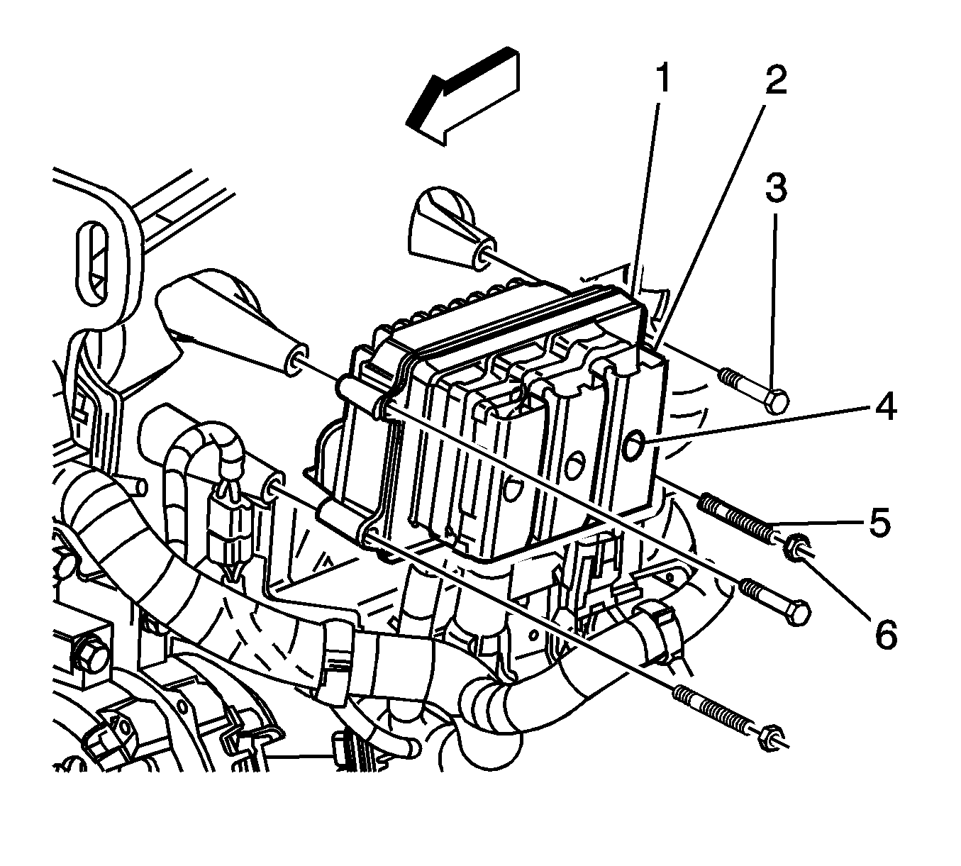
- Remove the powertrain control module (PCM) retaining bolts (3) and nuts (6).
- Slide the PCM off of the studs (5) and position the PCM out of the way.
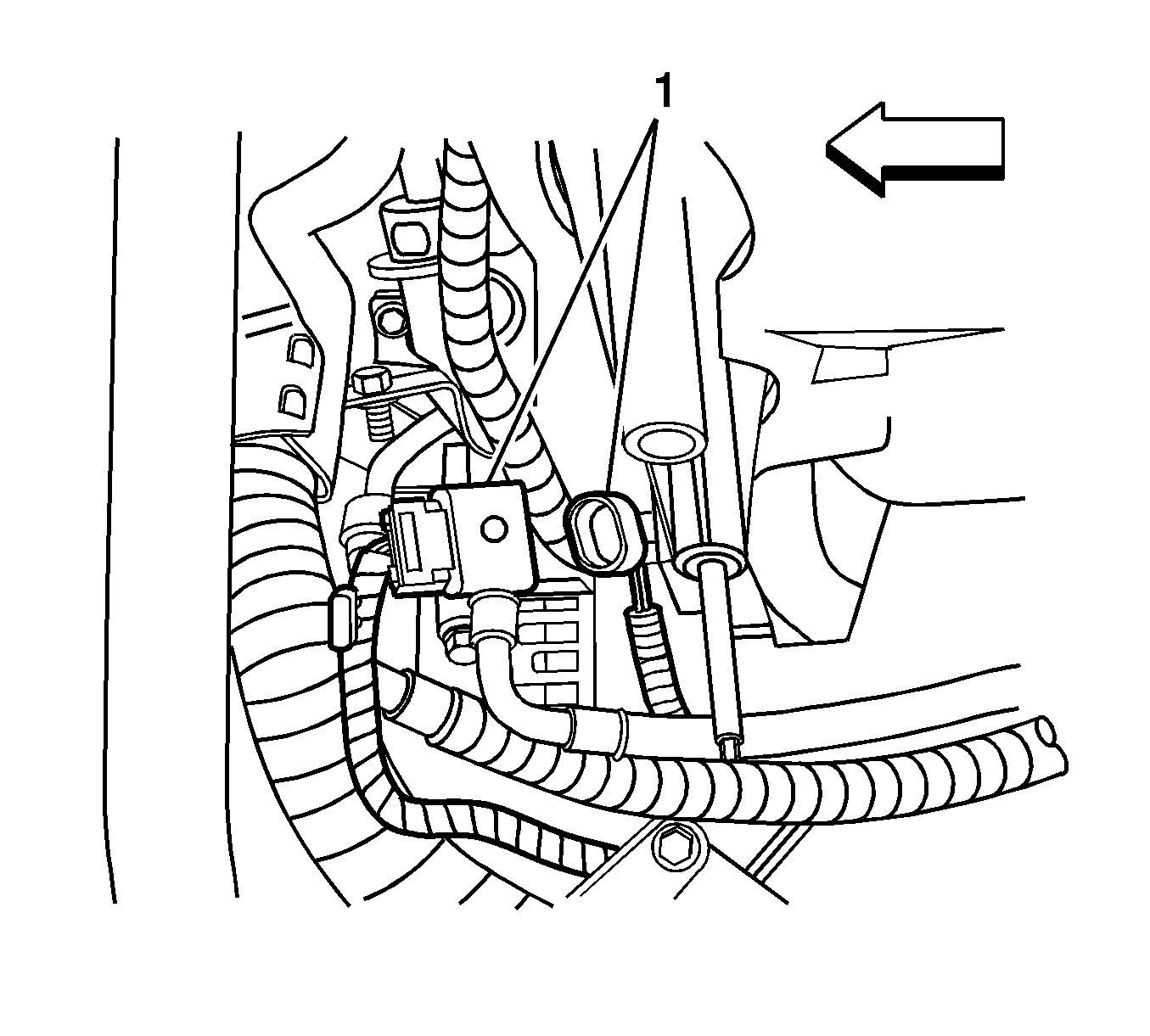
- Disconnect the engine coolant temperature sensor electrical connector.
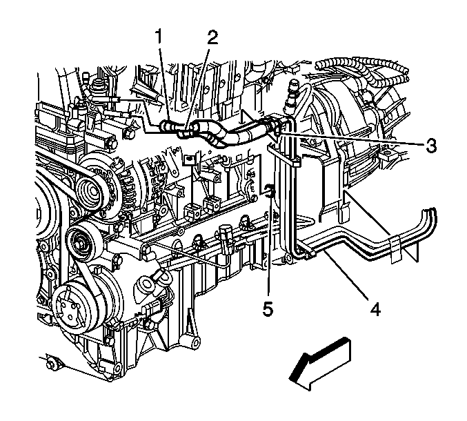
- Disconnect the fuel feed (1) and fuel return (2) pipes from the fuel rail. Refer to Metal Collar Quick Connect Fitting Service .
- Disconnect the EVAP purge pipe (5) from the EVAP canister purge valve.
- Disconnect the integral clip (3) from the wire harness bracket.
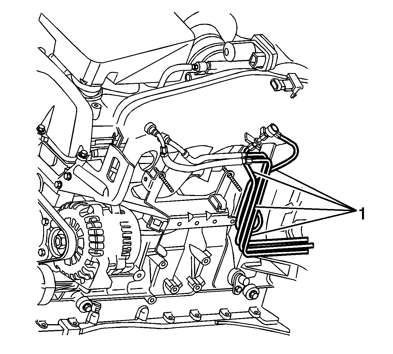
- Position the fuel feed and return pipes (1) above the PCM studs
- Raise the vehicle. Refer to Lifting and Jacking the Vehicle in General Information.
- Use the following procedure with two wheel drive (2WD):
- Use the following procedure with four wheel drive (4WD):
- Remove the EVAP/fuel hose/pipe assembly (4) from the fuel pipe clip at the rear of the engine.
- Disconnect the EVAP purge pipe at the fuel tank. Refer to Plastic Collar Quick Connect Fitting Service .
- Disconnect the chassis fuel return pipe (1) from the fuel tank fuel return pipe. Refer to Plastic Collar Quick Connect Fitting Service .
- Disconnect the chassis fuel feed pipe (3) from the fuel filter. Refer to Plastic Collar Quick Connect Fitting Service .
- Remove the EVAP/fuel hose/pipe assembly.
- Remove the EVAP/fuel hose/pipe assembly retaining clips.
- Remove the fuel feed (1), fuel return (2), or EVAP purge (3) pipe to be replaced.
Notice: Refer to Fuel and Evaporative Emission Hose/Pipe Connection Cleaning Notice in the Preface section.
| 10.1. | Remove the transmission support. Refer to Transmission Support Replacement in Frame and Underbody. |
| 10.2. | Lower the transmission slightly. |
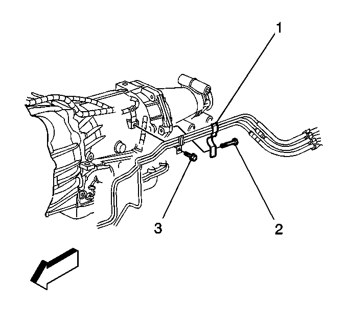
| 10.3. | Remove the EVAP/fuel hose/pipe assembly retaining bolt (3) from the transmission. |
| 10.4. | Disengage the EVAP/fuel hose/pipe assembly from the clip at the rear of the transmission. |
| 11.1. | Remove the transfer case. Refer to Transfer Case Assembly Replacement in Transfer Case - NVG 126-NP4 or Transfer Case Assembly Replacement in Transfer Case - NVG 226-NP8 depending on the model of transfer case the vehicle is equipped with. |
| 11.2. | Remove the transmission support. Refer to Transmission Support Replacement in Frame and Underbody. |
| 11.3. | Lower the transmission slightly. |
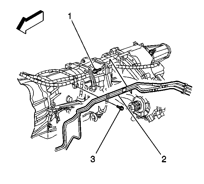
| 11.4. | Remove the EVAP/fuel hose/pipe assembly retaining bolt (3) from the transmission. |
| 11.5. | Remove the EVAP/fuel hose/pipe assembly from the clip at the rear of the transmission. |

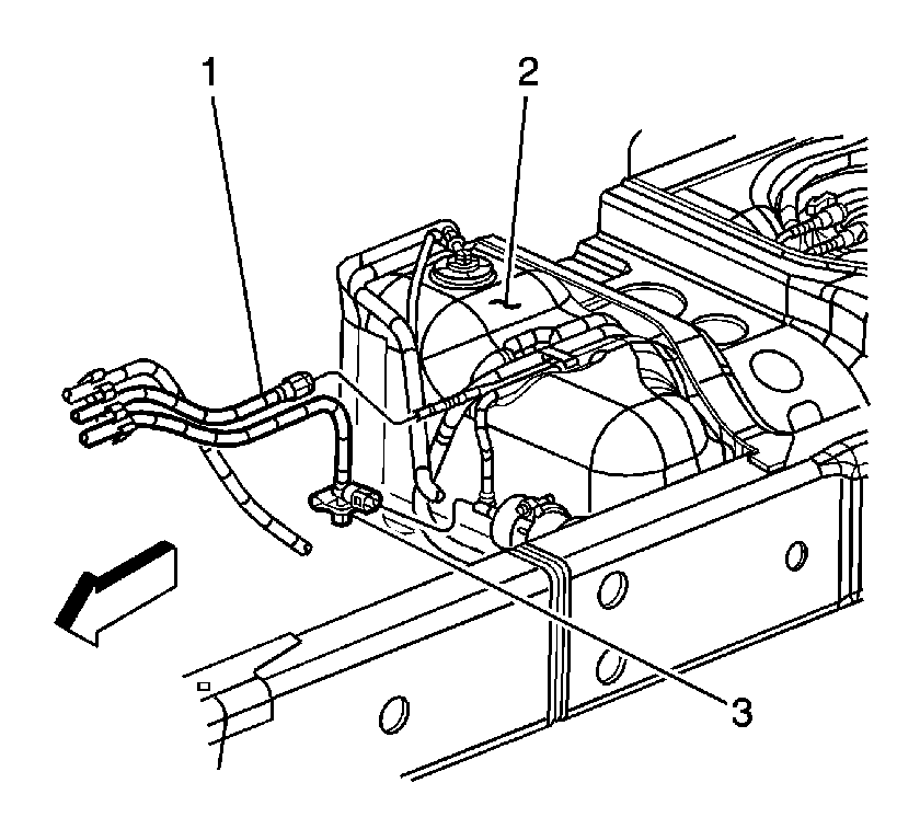
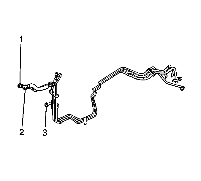
Important: Note the position of the EVAP/fuel hose/pipe assembly clips before disassembly.
Installation Procedure
- Place the new fuel feed (1), fuel return (2), or EVAP purge (3) pipe with the remaining pipes in the EVAP/fuel hose/pipe assembly.
- Install the EVAP/fuel hose/pipe assembly clips as noted during disassembly.
- Position the EVAP/fuel hose/pipe assembly along the engine and transmission.
- Connect the chassis fuel feed pipe (3) to the fuel filter.
- Connect the engine chassis fuel return pipe (1) to the fuel tank fuel return pipe.
- Connect the EVAP purge pipe at the fuel tank. Refer to Plastic Collar Quick Connect Fitting Service .
- Install the EVAP/fuel hose/pipe assembly (4) to the fuel pipe clip at the rear of the engine.
- Use the following procedure with two wheel drive (2WD):
- Use the following procedure with four wheel drive (4WD):
- Lower the vehicle.
- Connect the EVAP purge pipe (5) to the EVAP canister purge valve.
- Connect the integral clip (3) to the wire harness bracket.
- Connect the fuel feed (1) and fuel return (2) pipes to the fuel rail. Refer to Metal Collar Quick Connect Fitting Service .
- Connect the engine coolant temperature sensor electrical connector.
- Install the PCM onto the studs (5).
- Install the PCM retaining bolts (3).
- Install the PCM retaining nuts (6).
- Connect the negative battery cable. Refer to Battery Negative Cable Disconnection and Connection in Engine Electrical.
- Inspect for leaks using the following procedure:
- Install the fuel tank shield, if equipped. Refer to Fuel Tank Shield Replacement in Frame and Underbody.


| 8.1. | Install the EVAP/fuel hose/pipe assembly into the clip at the rear of the transmission. |
Notice: Refer to Fastener Notice in the Preface section.
| 8.2. | Position the EVAP/fuel hose/pipe assembly against the transmission and install the retaining bolt (3) through the EVAP/fuel hose/pipe assembly strap into the transmission. |
Tighten
Tighten the bolt to 3.75 N·m (33 lb in).
| 8.3. | Raise the transmission to the normal installed position. |
| 8.4. | Install the transmission support. Refer to Transmission Support Replacement in Frame and Underbody. |

| 9.1. | Install the EVAP/fuel hose/pipe assembly into the clip at the rear of the transmission. |
| 9.2. | Position the fuel EVAP/fuel hose/pipe assembly against the transmission and install the retaining bolt (3) through the EVAP/fuel hose/pipe assembly strap into the transmission. |
Tighten
Tighten the bolt to 3.75 N·m (33 lb in).
| 9.3. | Raise the transmission to the normal installed position. |
| 9.4. | Install the transmission support. Refer to Transmission Support Replacement in Frame and Underbody. |
| 9.5. | Install the transfer case. Refer to Transfer Case Assembly Replacement in Transfer Case - NVG 126-NP4 or Transfer Case Assembly Replacement in Transfer Case - NVG 226-NP8 depending on the model of transfer case the vehicle is equipped with. |


Tighten
Tighten the bolts to 8 N·m (71 lb in).
Tighten
Tighten the nuts to 8 N·m (71 lb in).
| 19.1. | Turn ON the ignition, with the engine OFF for 2 seconds. |
| 19.2. | Turn OFF the ignition, for 10 seconds. |
| 19.3. | Turn ON the ignition, with the engine OFF. |
| 19.4. | Inspect for fuel leaks. |
