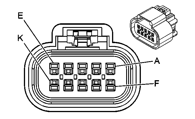
|
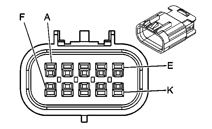
| ||||||||||||||
|---|---|---|---|---|---|---|---|---|---|---|---|---|---|---|---|
Connector Part Information |
| Connector Part Information |
| ||||||||||||
Pin | Wire Color | Circuit No. | Function | Pin | Wire Color | Circuit No. | Function | ||||||||
A | -- | -- | Not Used | A | -- | -- | Not Used | ||||||||
B | RD/BK | 380 | A/C Refrigerant Pressure Sensor Signal | B | RD/BK | 380 | A/C Refrigerant Pressure Sensor Signal | ||||||||
C | GY | 597 | 5-Volt Reference | C | GY | 597 | 5-Volt Reference | ||||||||
D | PK | 439 | Ignition 1 Voltage | D | PK | 439 | Ignition 1 Voltage | ||||||||
E | BK | 2751 | Low Reference | E | BK | 2751 | Low Reference | ||||||||
F | GY | 2700 | 5-Volt Reference | F | GY | 2700 | 5-Volt Reference | ||||||||
G | L-GN | 2278 | A/C Compressor Status Signal | G | L-GN | 2278 | A/C Compressor Status Signal | ||||||||
H | TN | 472 | IAT Sensor Signal | H | TN | 472 | IAT Sensor Signal | ||||||||
J | BK | 2760 | Low Reference | J | BK | 2760 | Low Reference | ||||||||
K | -- | -- | Not Used | K | -- | -- | Not Used | ||||||||
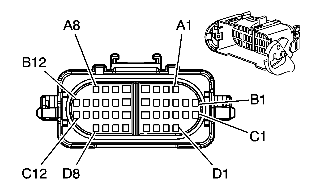
|
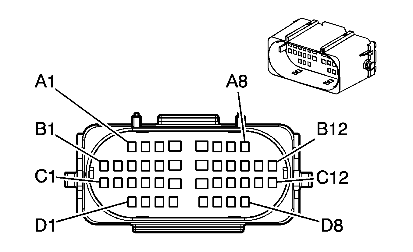
| ||||||||||||||
|---|---|---|---|---|---|---|---|---|---|---|---|---|---|---|---|
Connector Part Information |
| Connector Part Information |
| ||||||||||||
Pin | Wire Color | Circuit No. | Function | Pin | Wire Color | Circuit No. | Function | ||||||||
A1 | GY | 605 | 5-Volt Reference (4WD) | A1 | GY | 605 | 5-Volt Reference (4WD) | ||||||||
A2 | BN/WH | 1555 | Encoder Signal (4WD) | A2 | BN/WH | 1555 | Encoder Signal (4WD) | ||||||||
A3 | D-GN/WH | 817 | Vehicle Speed Signal (G67) | A3 | D-GN/WH | 817 | Vehicle Speed Signal (G67) | ||||||||
A4 | D-BU | 47 | Trailer Auxiliary Supply Voltage | A4 | D-BU | 47 | Trailer Auxiliary Supply Voltage | ||||||||
A5 | BK | 1552 | Motor Control A (4WD) | A5 | BK | 1552 | Motor Control A (4WD) | ||||||||
A6 | BN/WH | 1571 | Traction Control Switch Signal (NW7) | A6 | BN/WH | 1571 | Traction Control Switch Signal (NW7) | ||||||||
A7 | L-GN | 24 | Backup Lamp Supply Voltage (Z88) | A7 | L-GN | 24 | Backup Lamp Supply Voltage (Z88) | ||||||||
A8 | BK/WH | 1554 | Encoder Low Reference (4WD) | A8 | BK/WH | 1554 | Encoder Low Reference (4WD) | ||||||||
B1 | TN | 1569 | Lock Solenoid Control (NP8) | B1 | TN | 1569 | Lock Solenoid Control (NP8) | ||||||||
B2 | L-BU | 1296 | Axle Actuator - Control (NP8) | B2 | L-BU | 1296 | Axle Actuator - Control (NP8) | ||||||||
B3 | L-BU | 2221 | Signal High - Rear (4WD) | B3 | L-BU | 2221 | Signal High - Rear (4WD) | ||||||||
B4 | D-GN | 2222 | Signal Low - Rear (4WD) | B4 | D-GN | 2222 | Signal Low - Rear (4WD) | ||||||||
B5 | -- | -- | Not Used | B5 | -- | -- | Not Used | ||||||||
B6 | RD | 1553 | Motor Control B (4WD) | B6 | RD | 1553 | Motor Control B (4WD) | ||||||||
B7 | BN | 436 | AIR Pump Relay Control (4.2L w/K18) | B7 | BN | 436 | AIR Pump Relay Control (4.2L w/K1) | ||||||||
B8 | YE | 400 | Signal High - Front (4WD) | B8 | YE | 400 | Signal High - Front (4WD) | ||||||||
B9 | PU | 401 | Signal Low - Front (4WD) | B9 | PU | 401 | Signal Low - Front (4WD) | ||||||||
B10-B11 | -- | -- | Not Used | B10-B11 | -- | -- | Not Used | ||||||||
B12 | BN | 2109 | Trailer Park Lamps Supply Voltage | B12 | BN | 2109 | Trailer Park Lamps Supply Voltage | ||||||||
C1 | -- | -- | Not Used | C1 | -- | -- | Not Used | ||||||||
C2 | YE/BK | 1827 | Vehicle Speed Signal | C2 | YE/BK | 1827 | Vehicle Speed Signal | ||||||||
C3 | L-BU | 1122 | ABS/TCS Class 2 Serial Data | C3 | L-BU | 1122 | ABS/TCS Class 2 Serial Data | ||||||||
C4 | GY | 349 | Discriminating Sensor - Left - Signal | C4 | GY | 349 | Discriminating Sensor - Left - Signal | ||||||||
C5 | YE | 354 | Discriminating Sensor - Signal | C5 | YE | 354 | Discriminating Sensor - Signal | ||||||||
C6 | OG | 1140 | Battery Positive Voltage (BAE) | C6 | OG | 1140 | Battery Positive Voltage (BAE) | ||||||||
C7 | TN/BK | 5168 | Power Sounder Enable Signal (BAE) | C7 | TN/BK | 5168 | Power Sounder Enable Signal (BAE) | ||||||||
C8 | -- | -- | Not Used | C8 | -- | -- | Not Used | ||||||||
C9 | D-GN | 890 | Fuel Tank Pressure Sensor Signal | C9 | D-GN | 890 | Fuel Tank Pressure Sensor Signal | ||||||||
C10 | GY | 2709 | 5-Volt Reference | C10 | GY | 2709 | 5-Volt Reference | ||||||||
C11 | BK | 2759 | Low Reference | C11 | BK | 2759 | Low Reference | ||||||||
C12 | OG/BK | 510 | Low Reference (4.2L) | C12 | OG/BK | 510 | Low Reference (4.2L) | ||||||||
D1 | PU | 1589 | Fuel Level Sensor Signal - Primary | D1 | PU | 1589 | Fuel Level Sensor Signal - Primary | ||||||||
D2 | L-BU | 832 | Traction Control Active Signal (NW7) | D2 | L-BU | 832 | Traction Control Active Signal (NW7 Except W49) | ||||||||
D3 | WH | 1808 | Service Traction Control Signal (NW7) | D3 | WH | 1808 | Service Traction Control Signal (NW7) | ||||||||
D4-D5 | -- | -- | Not Used | D4-D5 | -- | -- | Not Used | ||||||||
D6 | YE | 1834 | Forward Discriminating Sensor Signal | D6 | YE | 1834 | Forward Discriminating Sensor Signal | ||||||||
D7 | D-GN | 1409 | Discriminating Sensor - Right - Signal | D7 | D-GN | 1409 | Discriminating Sensor - Right - Signal | ||||||||
D8 | -- | -- | Not Used | D8 | -- | -- | Not Used | ||||||||
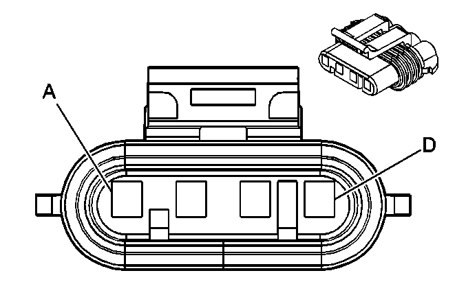
|
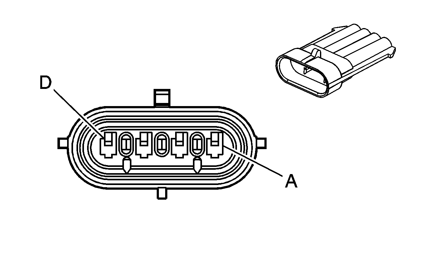
| ||||||||||||||
|---|---|---|---|---|---|---|---|---|---|---|---|---|---|---|---|
Connector Part Information |
| Connector Part Information |
| ||||||||||||
Pin | Wire Color | Circuit No. | Function | Pin | Wire Color | Circuit No. | Function | ||||||||
A | D-GN/WH | 711 | Left Headlamp High Beam Supply Voltage | A | YE | -- | Left Headlamp High Beam Supply Voltage | ||||||||
B | YE | 712 | Left Headlamp Low Beam Supply Voltage | B | OG | -- | Left Headlamp Low Beam Supply Voltage | ||||||||
C | BK | 350 | Ground | C | D-GN | -- | Ground | ||||||||
D | BK | 350 | Ground | D | WH | -- | Ground | ||||||||

|

| ||||||||||||||
|---|---|---|---|---|---|---|---|---|---|---|---|---|---|---|---|
Connector Part Information |
| Connector Part Information |
| ||||||||||||
Pin | Wire Color | Circuit No. | Function | Pin | Wire Color | Circuit No. | Function | ||||||||
A | L-GN/BK | 311 | Right Headlamp High Beam Supply Voltage | A | YE | -- | Right Headlamp High Beam Supply Voltage | ||||||||
B | TN/WH | 312 | Right Headlamp Low Beam Supply Voltage | B | OG | -- | Right Headlamp Low Beam Supply Voltage | ||||||||
C | BK | 250 | Ground | C | D-GN | -- | Ground | ||||||||
D | BK | 250 | Ground | D | WH | -- | Ground | ||||||||
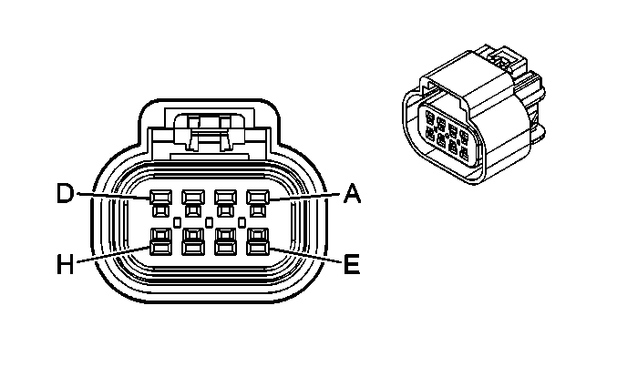
|
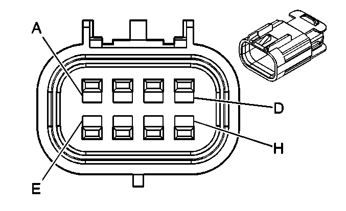
| ||||||||||||||
|---|---|---|---|---|---|---|---|---|---|---|---|---|---|---|---|
Connector Part Information |
| Connector Part Information |
| ||||||||||||
Pin | Wire Color | Circuit No. | Function | Pin | Wire Color | Circuit No. | Function | ||||||||
A | PK | 439 | Ignition 1 Voltage | A | PK | 439 | Ignition 1 Voltage | ||||||||
B | L-BU/BK | 844 | Fuel Injector 4 Control | B | L-BU/BK | 844 | Fuel Injector 4 Control | ||||||||
C | BK/WH | 845 | Fuel Injector 5 Control | C | BK/WH | 845 | Fuel Injector 5 Control | ||||||||
D | YE/BK | 846 | Fuel Injector 6 Control | D | YE/BK | 846 | Fuel Injector 6 Control | ||||||||
E | -- | -- | Not Used | E | -- | -- | Not Used | ||||||||
F | BK | 1744 | Fuel Injector 1 Control | F | BK | 1744 | Fuel Injector 1 Control | ||||||||
G | L-GN/BK | 1745 | Fuel Injector 2 Control | G | L-GN/BK | 1745 | Fuel Injector 2 Control | ||||||||
H | PK/BK | 1746 | Fuel Injector 3 Control | H | PK/BK | 1746 | Fuel Injector 3 Control | ||||||||

|

| ||||||||||||||
|---|---|---|---|---|---|---|---|---|---|---|---|---|---|---|---|
Connector Part Information |
| Connector Part Information |
| ||||||||||||
Pin | Wire Color | Circuit No. | Function | Pin | Wire Color | Circuit No. | Function | ||||||||
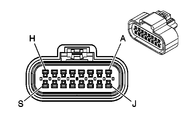
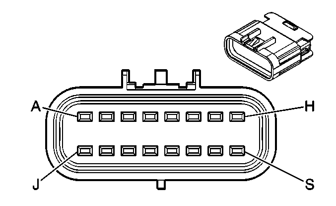
A | GY | 597 | 5-Volt Reference | A | GY | 597 | 5-Volt Reference | ||||||||
B | D-BU | 2364 | Cooling Fan Speed Signal | B | D-BU | 2364 | Cooling Fan Speed Signal | ||||||||
C | GY | 2365 | Low Reference | C | GY | 2365 | Low Reference | ||||||||
D | BN | 718 | Low Reference | D | BN | 718 | Low Reference | ||||||||
E | L-GN/BK | 735 | Ambient Air Temperature Sensor Signal | E | L-GN/BK | 735 | Ambient Air Temperature Sensor Signal | ||||||||
F | GY/BK | 1596 | Coolant Bypass Solenoid Control (Long Wheel Base Except XUV) | F | GY/BK | 1596 | Coolant Bypass Solenoid Control (Long Wheel Base Except XUV) | ||||||||
G | OG | 3040 | Battery Positive Voltage (4.2L w/Long Wheel Base Except XUV) | G | OG | 3040 | Battery Positive Voltage (4.2L w/Long Wheel Base Except XUV) | ||||||||
H | D-BU | 204 | A/C Low Pressure Sensor Signal | H | D-BU | 204 | A/C Low Pressure Sensor Signal | ||||||||
J | BK/WH | 174 | Low Washer Fluid Indicator Signal (U68) | J | BK/WH | 174 | Low Washer Fluid Indicator Signal (U68) | ||||||||
K | PK/BK | 109 | Hood Ajar Switch Signal (UA2) | K | PK/BK | 109 | Hood Ajar Switch Signal (UA2) | ||||||||
BN | 241 | Ignition 3 Voltage (4.2L w/Long Wheel Base Except XUV) | BN | 241 | Ignition 3 Voltage (4.2L w/Long Wheel Base Except XUV) | ||||||||||

|

| ||||||||||||||
|---|---|---|---|---|---|---|---|---|---|---|---|---|---|---|---|
Connector Part Information |
| Connector Part Information |
| ||||||||||||
Pin | Wire Color | Circuit No. | Function | Pin | Wire Color | Circuit No. | Function | ||||||||
A1 | -- | -- | Not Used | A1 | -- | -- | Not Used | ||||||||
A2 | GY | 2365 | Low Reference | A2 | GY | 2365 | Low Reference | ||||||||
A3 | GY | 2709 | 5-Volt Reference | A3 | GY | 2709 | 5-Volt Reference | ||||||||
A4-A5 | -- | -- | Not Used | A4-A5 | -- | -- | Not Used | ||||||||
A6 | PU | 1272 | Low Reference | A6 | PU | 1272 | Low Reference | ||||||||
A7 | L-BU | 1162 | APP Sensor 2 Signal | A7 | L-BU | 1162 | APP Sensor 2 Signal | ||||||||
A8 | D-GN | 890 | Fuel Tank Pressure Sensor Signal | A8 | D-GN | 890 | Fuel Tank Pressure Sensor Signal | ||||||||
B1 | GY | 397 | Cruise Control On Switch Signal | B1 | GY | 397 | Cruise Control On Switch Signal | ||||||||
B2 | TN | 1274 | 5-Volt Reference | B2 | TN | 1274 | 5-Volt Reference | ||||||||
B3 | BN | 1271 | Low Reference | B3 | BN | 1271 | Low Reference | ||||||||
B4 | D-BU | 1161 | APP Sensor 1 Signal | B4 | D-BU | 1161 | APP Sensor 1 Signal | ||||||||
B5 | WH/BK | 1164 | 5-Volt Reference | B5 | WH/BK | 1164 | 5-Volt Reference | ||||||||
B6-B7 | -- | -- | Not Used | B6-B7 | -- | -- | Not Used | ||||||||
B8 | YE | 710 | Class 2 Serial Data | B8 | YE | 710 | Class 2 Serial Data | ||||||||
B9 | L-BU | 1320 | Stop Lamp Supply Voltage | B9 | L-BU | 1320 | Stop Lamp Supply Voltage | ||||||||
B10 | D-BU | 2364 | Cooling Fan Speed Signal | B10 | D-BU | 2364 | Cooling Fan Speed Signal | ||||||||
B11 | YE/BK | 1827 | Vehicle Speed Signal | B11 | YE/BK | 1827 | Vehicle Speed Signal | ||||||||
B12 | GY/BK | 87 | Cruise Control Resume/Accel Switch Signal | B12 | GY/BK | 87 | Cruise Control Resume/Accel Switch Signal | ||||||||
C1 | WH | 121 | Engine Speed Signal | C1 | WH | 121 | Engine Speed Signal | ||||||||
C2 | L-BU | 6106 | High Speed GMLAN Serial Data (-) | C2 | L-BU | 6106 | High Speed GMLAN Serial Data (-) | ||||||||
C3 | BK | 2759 | Low Reference | C3 | BK | 2759 | Low Reference | ||||||||
C4 | PK | 1020 | Ignition 0 Voltage | C4 | PK | 1020 | Ignition 0 Voltage | ||||||||
C5 | BN/WH | 419 | MIL Control | C5 | BN/WH | 419 | MIL Control | ||||||||
C6-C7 | -- | -- | Not Used | C6-C7 | -- | -- | Not Used | ||||||||
C8 | PU | 420 | TCC Brake Switch/Cruise Control Release Signal | C8 | PU | 420 | TCC Brake Switch/Cruise Control Release Signal | ||||||||
C9 | D-BU | 6105 | High Speed GMLAN Serial Data (+) | C9 | D-BU | 6105 | High Speed GMLAN Serial Data (+) | ||||||||
C10 | PU | 1589 | Fuel Level Sensor Signal - Primary | C10 | PU | 1589 | Fuel Level Sensor Signal - Primary | ||||||||
C11 | D-GN | 1049 | ECM/PCM/VCM Class 2 Serial Data | C11 | D-GN | 1049 | ECM/PCM/VCM Class 2 Serial Data | ||||||||
C12 | D-GN/WH | 817 | Vehicle Speed Signal | C12 | D-GN/WH | 817 | Vehicle Speed Signal | ||||||||
D1 | D-BU | 84 | Cruise Control Set/Coast Switch Signal | D1 | D-BU | 84 | Cruise Control Set/Coast Switch Signal | ||||||||
D2 | L-GN | 2278 | A/C Compressor Status Signal | D2 | L-GN | 2278 | A/C Compressor Status Signal | ||||||||
D3 | GY | 597 | 5-Volt Reference | D3 | GY | 597 | 5-Volt Reference | ||||||||
D4 | -- | -- | Not Used | D4 | -- | -- | Not Used | ||||||||
D5 | -- | -- | Not Used | D5 | -- | -- | Not Used | ||||||||
D6 | OG/BK | 1786 | Ignition Lock Cylinder Control Actuator Signal | D6 | OG/BK | 1786 | Ignition Lock Cylinder Control Actuator Signal | ||||||||
D7 | GY/BK | 1694 | 4WD Low Signal (NP8) | D7 | GY/BK | 1694 | 4WD Low Signal (NP8) | ||||||||
D8 | YE | 243 | Accessory Voltage | D8 | YE | 243 | Accessory Voltage | ||||||||
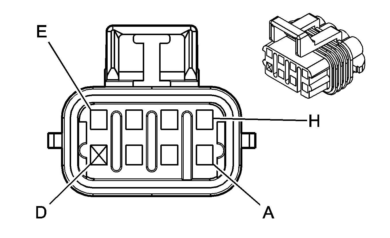
|
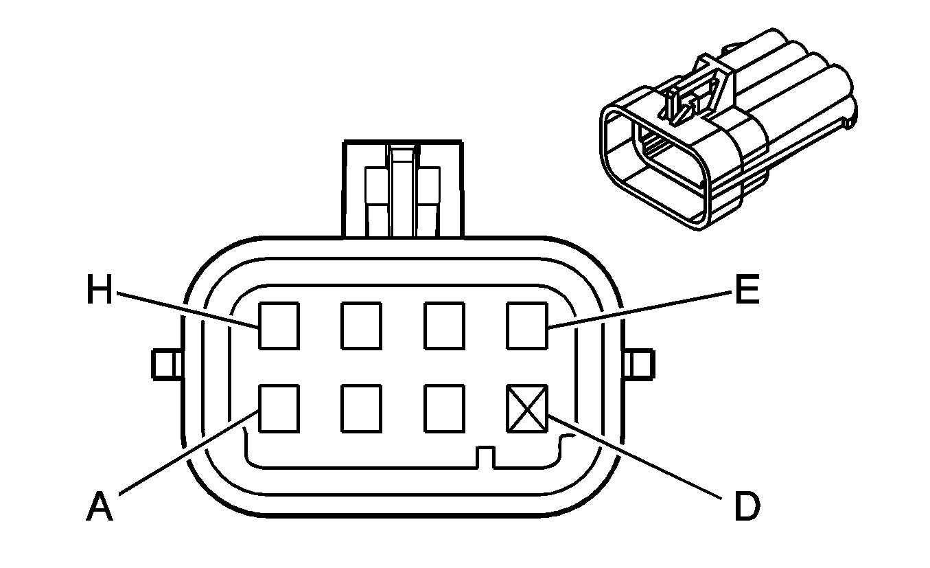
| ||||||||||||||
|---|---|---|---|---|---|---|---|---|---|---|---|---|---|---|---|
Connector Part Information |
| Connector Part Information |
| ||||||||||||
Pin | Wire Color | Circuit No. | Function | Pin | Wire Color | Circuit No. | Function | ||||||||
A | BK | 550 | Ground | A | BK | 151 | Ground | ||||||||
B | RD/WH | 2122 | IC 2 Control | B | RD | 2127 | IC 2 Control | ||||||||
C | D-GN/WH | 2124 | IC 4 Control | C | D-GN | 2125 | IC 4 Control | ||||||||
D | -- | -- | Not Used | D | -- | -- | Not Used | ||||||||
E | BN/WH | 2130 | Low Reference | E | BN | 2129 | Low Reference | ||||||||
F | L-BU/WH | 2126 | IC 6 Control | F | L-BU | 2123 | IC 6 Control | ||||||||
G | PU/WH | 2128 | IC 8 Control | G | PU | 2121 | IC 8 Control | ||||||||
H | PK | 1339 | Ignition 1 Voltage | H | PK | 39 | Ignition 1 Voltage | ||||||||

|

| ||||||||||||||
|---|---|---|---|---|---|---|---|---|---|---|---|---|---|---|---|
Connector Part Information |
| Connector Part Information |
| ||||||||||||
Pin | Wire Color | Circuit No. | Function | Pin | Wire Color | Circuit No. | Function | ||||||||
A | BK | 550 | Ground | A | BK | 151 | Ground | ||||||||
B | RD | 2127 | IC 7 Control | B | RD | 2127 | IC 7 Control | ||||||||
C | D-GN | 2125 | IC 5 Control | C | D-GN | 2125 | IC 5 Control | ||||||||
D | -- | -- | Not Used | D | -- | -- | Not Used | ||||||||
E | BN | 2129 | Low Reference | E | BN | 2129 | Low Reference | ||||||||
F | L-BU | 2123 | IC 3 Control | F | L-BU | 2123 | IC 3 Control | ||||||||
G | PU | 2121 | IC 1 Control | G | PU | 2121 | IC 1 Control | ||||||||
H | PK | 1239 | Ignition 1 Voltage | H | PK | 39 | Ignition 1 Voltage | ||||||||
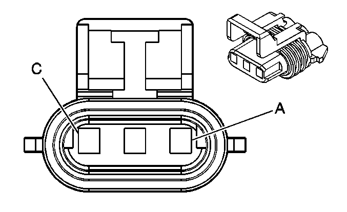
|
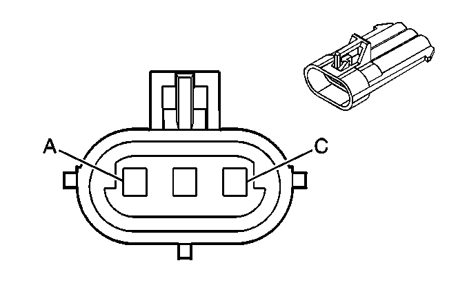
| ||||||||||||||
|---|---|---|---|---|---|---|---|---|---|---|---|---|---|---|---|
Connector Part Information |
| Connector Part Information |
| ||||||||||||
Pin | Wire Color | Circuit No. | Function | Pin | Wire Color | Circuit No. | Function | ||||||||
A | RD | 631 | 12-Volt Reference | A | RD | -- | 12-Volt Reference | ||||||||
B | PK/BK | 632 | Low Reference | B | PK/BK | -- | Low Reference | ||||||||
C | BN/WH | 633 | CMP Sensor Signal | C | BN/WH | -- | CMP Sensor Signal | ||||||||
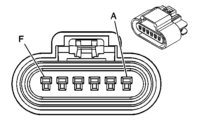
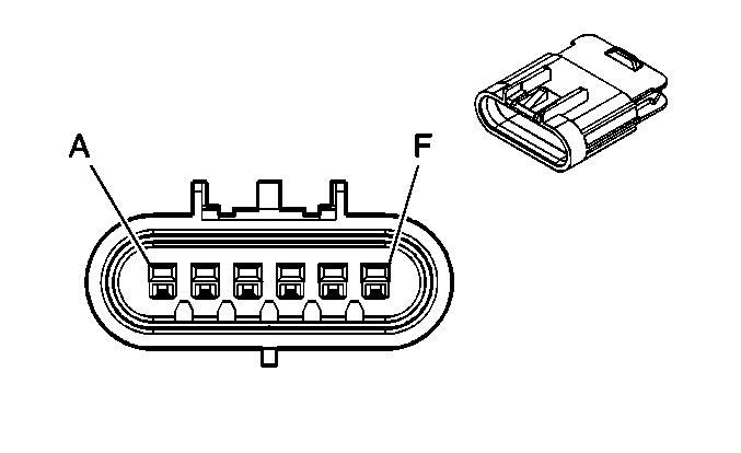
|
| ||||||||||||||
|---|---|---|---|---|---|---|---|---|---|---|---|---|---|---|---|
Connector Part Information |
| Connector Part Information |
| ||||||||||||
Pin | Wire Color | Circuit No. | Function | Pin | Wire Color | Circuit No. | Function | ||||||||
A | BK | 250 | Ground | A | BK | 250 | Ground | ||||||||
B | WH | 2368 | Cooling Fan Clutch Supply Voltage | B | WH | 2368 | Cooling Fan Clutch Supply Voltage | ||||||||
C | GY | 2365 | Low Reference | C | GY/WH | 2365 | Low Reference | ||||||||
D | D-BU | 2364 | Cooling Fan Speed Signal | D | D-BU | 2364 | Cooling Fan Speed Signal | ||||||||
E | GY | 597 | 5-Volt Reference | E | GY | 597 | 5-Volt Reference | ||||||||
F | -- | -- | Not Used | F | -- | -- | Not Used | ||||||||
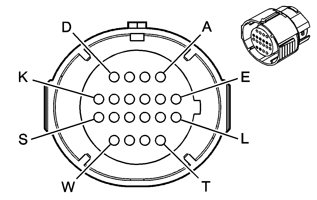
|
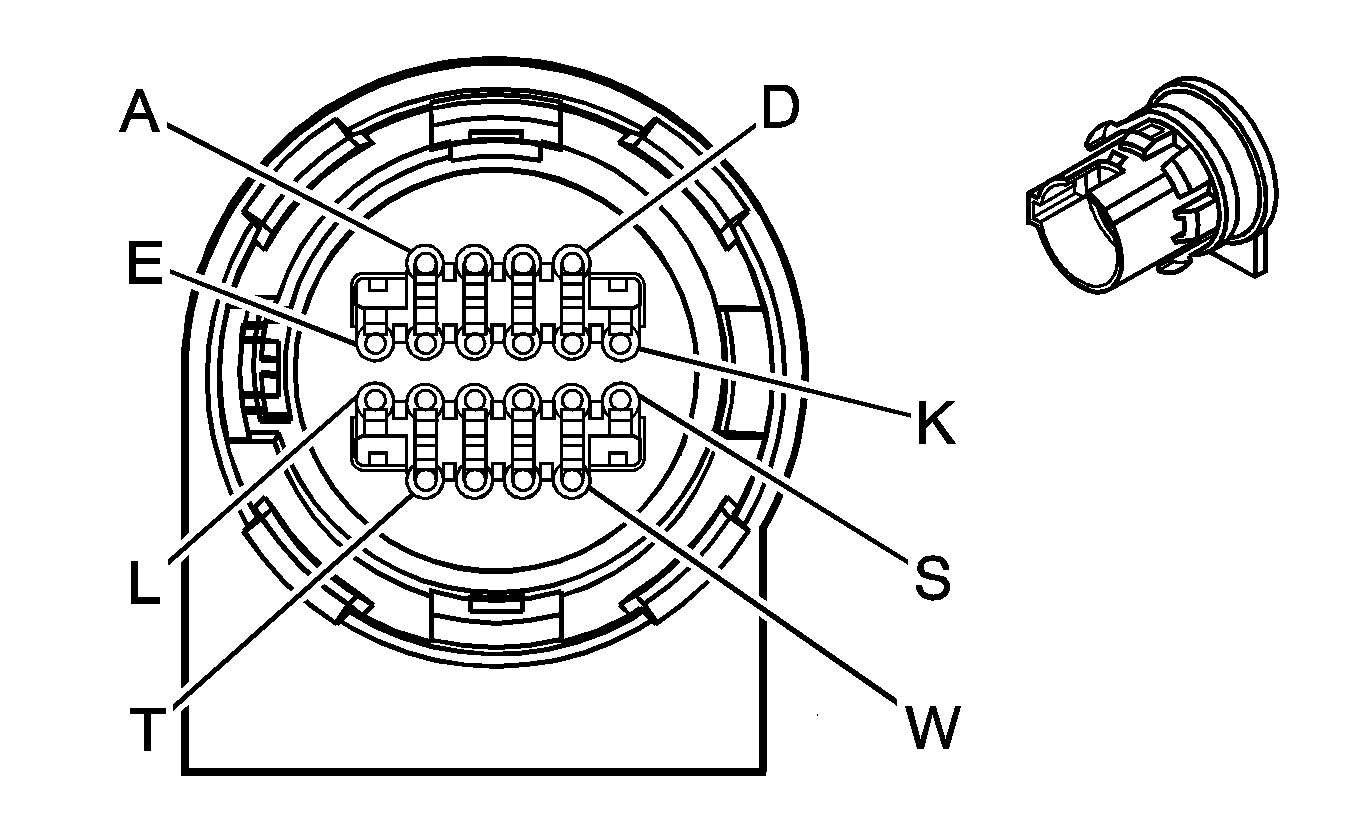
| ||||||||||||||
|---|---|---|---|---|---|---|---|---|---|---|---|---|---|---|---|
Connector Part Information |
| Connector Part Information |
| ||||||||||||
Pin | Wire Color | Circuit No. | Function | Pin | Wire Color | Circuit No. | Function | ||||||||
A | L-GN | 1222 | 1-2 Shift Solenoid Valve Control | A | L-GN | 1222 | 1-2 Shift Solenoid Valve Control | ||||||||
B | YE/BK | 1223 | 2-3 Shift Solenoid Valve Control | B | YE | 1223 | 2-3 Shift Solenoid Valve Control | ||||||||
C | RD/BK | 1228 | PC Solenoid Valve High Control (Sol. A) | C | PU | 1228 | PC Solenoid Valve High Control (Sol. A) | ||||||||
D | L-BU/WH | 1229 | PC Solenoid Valve Low Control (Sol. A) | D | L-BU | 1229 | PC Solenoid Valve Low Control (Sol. A) | ||||||||
E | PK | 1020 | Ignition 0 Voltage (4.2L) | E | RD | 839 | Ignition 0 Voltage (4.2L) | ||||||||
PK | 139 | Ignition 1 Voltage (5.3L) | RD | 839 | Ignition 1 Voltage (5.3L) | ||||||||||
F-K | -- | -- | Not Used | F-K | -- | -- | Not Used | ||||||||
L | YE/BK | 1227 | TFT Sensor Signal | L | BN | 1227 | TFT Sensor Signal | ||||||||
M | BK | 2762 | Low Reference | M | GY | 452 | Low Reference | ||||||||
N | PK | 1224 | Transmission Fluid Pressure Switch Signal A | N | PK | 1224 | Transmission Fluid Pressure Switch Signal A | ||||||||
P | RD | 1226 | Transmission Fluid Pressure Switch Signal C | P | OG | 1226 | Transmission Fluid Pressure Switch Signal C | ||||||||
R | D-BU | 1225 | Transmission Fluid Pressure Switch Signal B | R | D-BU | 1225 | Transmission Fluid Pressure Switch Signal B | ||||||||
S | WH | 687 | 3-2 Shift Solenoid Valve Control | S | WH | 687 | 3-2 Shift Solenoid Valve Control | ||||||||
T | TN/BK | 422 | TCC Solenoid Valve Control | T | BK | 422 | TCC Solenoid Valve Control | ||||||||
U | BN | 418 | TCC PWM Solenoid Valve Control | U | TN | 418 | TCC PWM Solenoid Valve Control | ||||||||
V-W | -- | -- | Not Used | V-W | -- | -- | Not Used | ||||||||
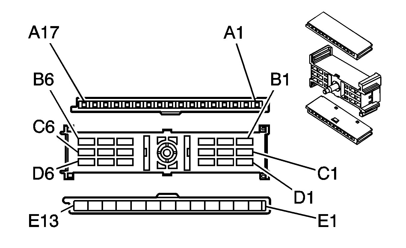
|
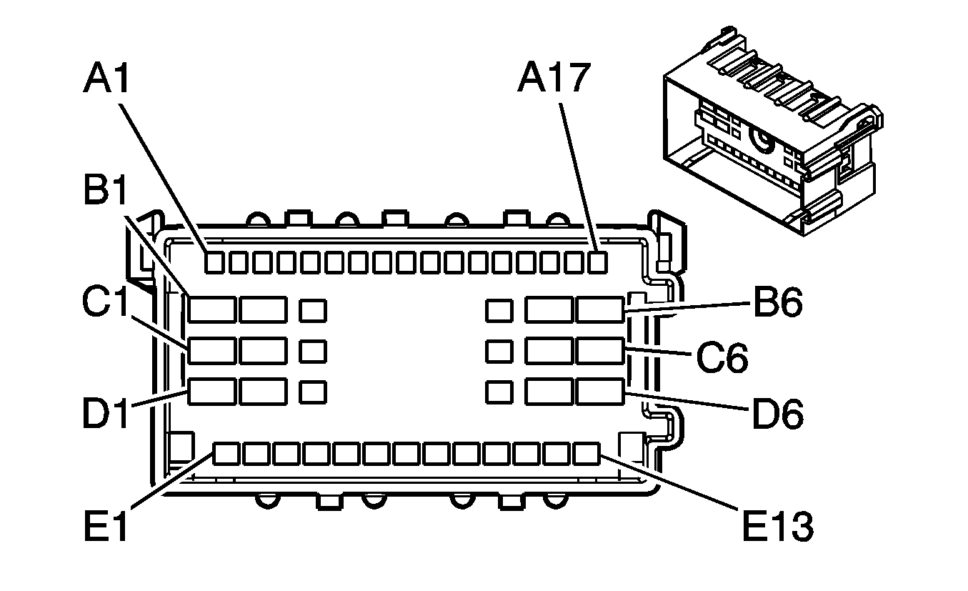
| ||||||||||||||||||||||
|---|---|---|---|---|---|---|---|---|---|---|---|---|---|---|---|---|---|---|---|---|---|---|---|
Connector Part Information |
| Connector Part Information |
| ||||||||||||||||||||
Pin | Wire Color | Circuit No. | Function | Pin | Wire Color | Circuit No. | Function | ||||||||||||||||
A1 | OG | 5286 | Adjustable Pedals Relay Forward Control (JF4) | A1 | PU | 5286 | Adjustable Pedals Relay Forward Control (JF4) | ||||||||||||||||
A2 | PK | 639 | Ignition 1 Voltage | A2 | PK | 639 | Ignition 1 Voltage | ||||||||||||||||
A3 | BN | 2309 | Front Park Lamps Supply Voltage | A3 | BN | 2309 | Front Park Lamps Supply Voltage | ||||||||||||||||
A4 | L-GN | 1427 | Right Turn Signal Switch Signal | A4 | L-GN | 1427 | Right Turn Signal Switch Signal | ||||||||||||||||
A5 | D-GN | 1428 | Left Turn Signal Switch Signal | A5 | D-GN | 1428 | Left Turn Signal Switch Signal | ||||||||||||||||
A6 | BK | 58 | Right Cornering Lamp Supply Voltage (T87) | A6 | BK | 58 | Right Cornering Lamp Supply Voltage (T87) | ||||||||||||||||
A7 | OG | 57 | Left Cornering Lamp Supply Voltage (T87) | A7 | OG | 57 | Left Cornering Lamp Supply Voltage (T87) | ||||||||||||||||
A8 | PK | 5285 | Adjustable Pedals Relay Forward Control (JF4) | A8 | OG/BK | 5285 | Adjustable Pedals Relay Forward Control (JF4) | ||||||||||||||||
A9 | OG/BK | 1816 | DIC Set/Reset Switch Signal (STW) | A9 | OG | 1816 | DIC Set/Reset Switch Signal (STW) | ||||||||||||||||
A10 | PU | 1358 | DIC Switch Signal (STW) | A10 | D-GN/WH | 1358 | DIC Switch Signal (STW) | ||||||||||||||||
A11 | WH | 111 | Hazard Switch Signal | A11 | WH | 111 | Hazard Switch Signal | ||||||||||||||||
A12 | L-GN | 1011 | Remote Radio Control Signal (STW) | A12 | L-GN | 1011 | Remote Radio Control Signal (STW) | ||||||||||||||||
A13 | D-BU | 894 | DIC Toggle Switch Signal (STW) | A13 | D-BU | 894 | DIC Toggle Switch Signal (STW) | ||||||||||||||||
A14 | YE | 1327 | DIC Fuel Signal (STW) | A14 | YE | 1327 | DIC Fuel Signal (STW) | ||||||||||||||||
A15 | BN/WH | 230 | Instrument Panel Lamps Dimming Control (STW) | A15 | BN/WH | 230 | Instrument Panel Lamps Dimming Control (STW) | ||||||||||||||||
A16 | BK | 2250 | Ground | A16 | BK | 2250 | Ground | ||||||||||||||||
A17 | OG | 3240 | Battery Positive Voltage (JF4) | A17 | BK | 3240 | Battery Positive Voltage (JF4) | ||||||||||||||||
B1-B2 | -- | -- | Not Used | B1-B2 | -- | -- | Not Used | ||||||||||||||||
B3 | PK | 2283 | 12-Volt Reference (STW) | B3 | WH | 2283 | 12-Volt Reference (STW) | ||||||||||||||||
WH | 2283 | 12-Volt Reference (STW/CD6) | |||||||||||||||||||||
B4 | -- | -- | Not Used | B4 | -- | -- | Not Used | ||||||||||||||||
B5 | RD | 142 | Battery Positive Voltage | B5 | RD | 142 | Battery Positive Voltage | ||||||||||||||||
B6 | BN | 4 | Accessory Voltage | B6 | BN | 4 | Accessory Voltage | ||||||||||||||||
C1 | YE | 5 | Crank Voltage | C1 | YE | 5 | Crank Voltage | ||||||||||||||||
C2 | RD/WH | 812 | 12-Volt Reference (Domestic) | C2 | RD/WH | 812 | 12-Volt Reference (Domestic) | ||||||||||||||||
WH | 1132 | DLC Class 2 Serial Data (BAE) | PU | 1132 | DLC Class 2 Serial Data (BAE) | ||||||||||||||||||
C3 | WH | 710 | Class 2 Serial Data (BAE) | C3 | YE | 710 | Class 2 Serial Data (BAE) | ||||||||||||||||
C4 | OG/BK | 1835 | Security System Sensor Low Reference (Domestic) | C4 | BK | 1835 | Security System Sensor Low Reference (Domestic) | ||||||||||||||||
PK | 1020 | Ignition 0 Voltage (BAE) | PK | 1020 | Ignition 0 Voltage (BAE) | ||||||||||||||||||
C5 | WH | 1390 | Off/Run/Crank Voltage | C5 | WH | 1390 | Off/Run/Crank Voltage | ||||||||||||||||
C6 | PK | 3 | Ignition 1 Voltage | C6 | PK | 3 | Ignition 1 Voltage | ||||||||||||||||
D1 | OG | 300 | Ignition 3 Voltage | D1 | OG | 300 | Ignition 3 Voltage | ||||||||||||||||
D2 | RD/WH | 342 | Battery Positive Voltage | D2 | RD | 342 | Battery Positive Voltage | ||||||||||||||||
D3 | OG | 1140 | Battery Positive Voltage (BAE) | D3 | OG | 1140 | Battery Positive Voltage (BAE) | ||||||||||||||||
YE | 1836 | Security System Sensor Signal (Domestic) | YE | 1836 | Security System Sensor Signal (Domestic) | ||||||||||||||||||
D4 | BK/YE | 28 | Horn Relay Control | D4 | BK | 28 | Horn Relay Control | ||||||||||||||||
BK | 28 | Horn Relay Control | |||||||||||||||||||||
D5-D6 | -- | -- | Not Used | D5-D6 | -- | -- | Not Used | ||||||||||||||||
E1 | -- | -- | Not Used | E1 | -- | -- | Not Used | ||||||||||||||||
E2 | TN | 751 | Ground | E2 | BK/WH | 751 | Ground | ||||||||||||||||
E3 | GY/BK | 87 | Cruise Control Resume/Accel Switch Signal | E3 | GY/BK | 87 | Cruise Control Resume/Accel Switch Signal | ||||||||||||||||
E4 | PK | 94 | Windshield Wiper Switch Signal 1 | E4 | PK | 94 | Windshield Wiper Switch Signal 1 | ||||||||||||||||
E5 | D-BU/WH | 477 | Windshield Wiper Switch High Signal | E5 | D-BU | 477 | Windshield Wiper Switch High Signal | ||||||||||||||||
E6 | L-GN | 80 | Key In Ignition Switch Signal | E6 | L-GN | 80 | Key In Ignition Switch Signal | ||||||||||||||||
E7 | YE | 1996 | Ignition Lock Cylinder Control Actuator Signal | E7 | YE | 1996 | Ignition Lock Cylinder Control Actuator Signal | ||||||||||||||||
E8 | GY | 478 | Windshield Wiper Switch Supply Voltage | E8 | GY | 478 | Windshield Wiper Switch Supply Voltage | ||||||||||||||||
E9 | GY/WH | 397 | Cruise Control ON Switch Signal | E9 | GY | 397 | Cruise Control ON Switch Signal | ||||||||||||||||
E10 | D-BU | 84 | Cruise Control Set/Coast Switch Signal | E10 | D-BU | 84 | Cruise Control Set/Coast Switch Signal | ||||||||||||||||
E11 | YE/BK | 307 | Headlamp Switch Flash to Pass Signal | E11 | YE | 307 | Headlamp Switch Flash to Pass Signal | ||||||||||||||||
E12 | L-GN | 11 | Headlamp High Beam Supply Voltage | E12 | L-GN | 11 | Headlamp High Beam Supply Voltage | ||||||||||||||||
E13 | BN | 341 | Ignition 3 Voltage | E13 | BN | 341 | Ignition 3 Voltage | ||||||||||||||||
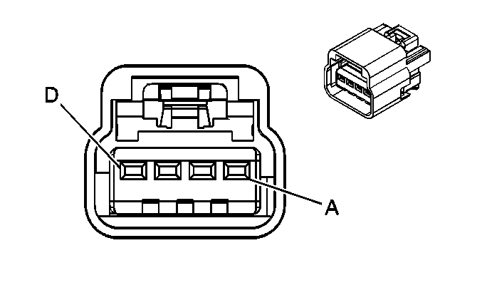
|
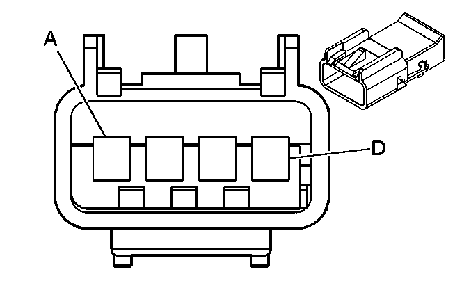
| ||||||||||||||
|---|---|---|---|---|---|---|---|---|---|---|---|---|---|---|---|
Connector Part Information |
| Connector Part Information |
| ||||||||||||
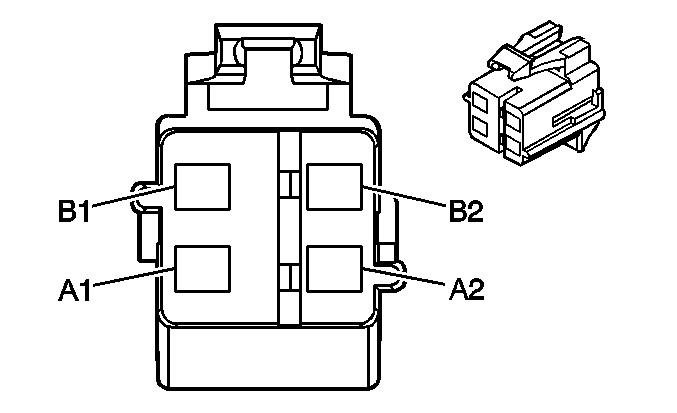
Pin | Wire Color | Circuit No. | Function | Pin | Wire Color | Circuit No. | Function | ||||||||
A | OG/BK | 2119 | Seat Belt Pretensioner - Left - Low Control | A | OG/BK | 2119 | Seat Belt Pretensioner - Left - Low Control | ||||||||
B | BK/WH | 2118 | Seat Belt Pretensioner - Left - Low Control | B | BK/WH | 2118 | Seat Belt Pretensioner - Left - Low Control | ||||||||
C | L-GN | 2116 | Seat Belt Pretensioner - Right - High Control | C | L-GN | 2116 | Seat Belt Pretensioner - Right - High Control | ||||||||
D | OG | 2117 | Seat Belt Pretensioner - Right - Low Control | D | OG | 2117 | Seat Belt Pretensioner - Right - Low Control | ||||||||
|
| ||||||||||||||
|---|---|---|---|---|---|---|---|---|---|---|---|---|---|---|---|
Connector Part Information |
| Connector Part Information |
| ||||||||||||
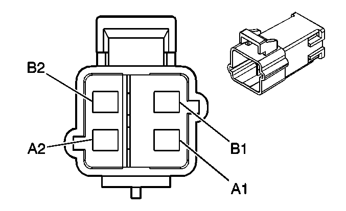
Pin | Wire Color | Circuit No. | Function | Pin | Wire Color | Circuit No. | Function | ||||||||
A1 | D-GN | 2105 | Side Impact Module - Left - High Control | A1 | D-GN | 2105 | Side Impact Module - Left - High Control | ||||||||
A2 | BN | 2106 | Side Impact Module - Left - Low Control | A2 | BN | 2106 | Side Impact Module - Left - Low Control | ||||||||
B1 | GY | 2103 | Side Impact Module - Right - High Control | B1 | GY | 2103 | Side Impact Module - Right - High Control | ||||||||
B2 | D-BU | 2104 | Side Impact Module - Right - Low Control | B2 | D-BU | 2104 | Side Impact Module - Right - Low Control | ||||||||
|

| ||||||||||||||
|---|---|---|---|---|---|---|---|---|---|---|---|---|---|---|---|
Connector Part Information |
| Connector Part Information |
| ||||||||||||
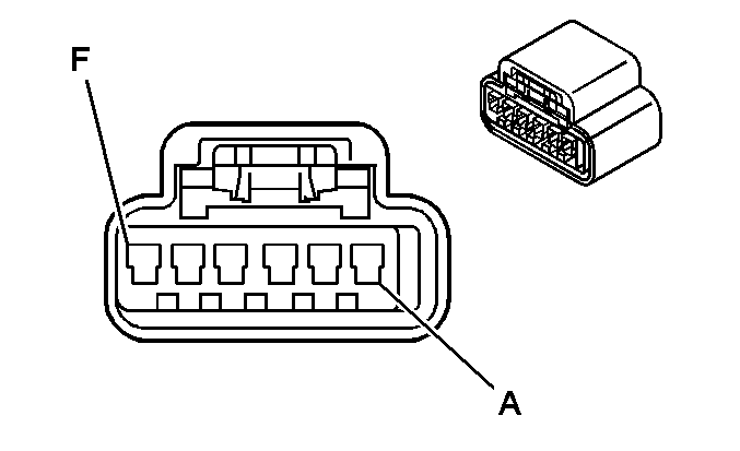
Pin | Wire Color | Circuit No. | Function | Pin | Wire Color | Circuit No. | Function | ||||||||
A | BK/WH | 372 | Audio Common | A | BK/WH | 372 | Audio Common | ||||||||
B | D-GN/WH | 368 | Right Audio Signal (+) | B | D-GN/WH | 368 | Right Audio Signal (+) | ||||||||
C | BN/WH | 367 | Left Audio Signal (+) | C | BN/WH | 367 | Left Audio Signal (+) | ||||||||
D | BARE | 1573 | Drain Wire | D | BARE | 1573 | Drain Wire | ||||||||
E-F | -- | -- | Not Used | E-F | -- | -- | Not Used | ||||||||
|
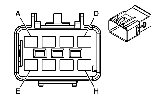
| ||||||||||||||
|---|---|---|---|---|---|---|---|---|---|---|---|---|---|---|---|
Connector Part Information |
| Connector Part Information |
| ||||||||||||
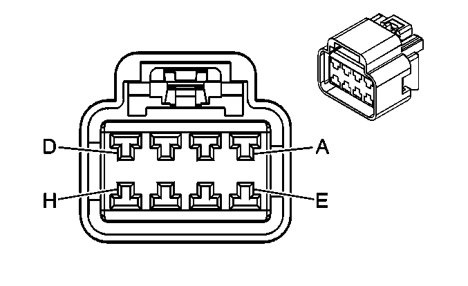
Pin | Wire Color | Circuit No. | Function | Pin | Wire Color | Circuit No. | Function | ||||||||
A | BK/WH | 372 | Audio Common (U42/U2K) | A | BK/WH | 372 | Audio Common (U42/U2K) | ||||||||
BK/WH | 372 | Audio Common (U42 w/U2K) | |||||||||||||
B | D-GN/WH | 368 | Right Audio Signal (+) (U42/U2K) | B | D-GN/WH | 368 | Right Audio Signal (+) (U42/U2K) | ||||||||
D-GN/WH | 368 | Right Audio Signal (+) (U42 w/U2K) | |||||||||||||
C | BN/WH | 367 | Left Audio Signal (+) (U42/U2K) | C | BN/WH | 367 | Left Audio Signal (+) (U42/U2K) | ||||||||
BN/WH | 367 | Left Audio Signal (+) (U42 w/U2K) | |||||||||||||
D | BARE | 1573 | Drain Wire(U42/U2K) | D | BARE | 1573 | Drain Wire (U42/U2K) | ||||||||
E | -- | -- | Not Used | E | -- | -- | Not Used | ||||||||
F | OG | 340 | Battery Positive Voltage (U2K) | F | OG | 340 | Battery Positive Voltage (U2K) | ||||||||
G | YE | 5679 | Class 2 Serial Data (U2K) | G | YE | 5679 | Class 2 Serial Data (U2K) | ||||||||
H | BK/WH | 751 | Ground (U2K) | H | BK/WH | 751 | Ground (U2K) | ||||||||
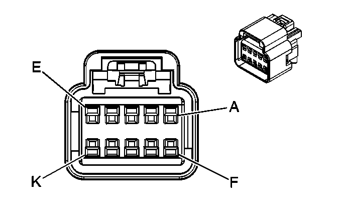
|
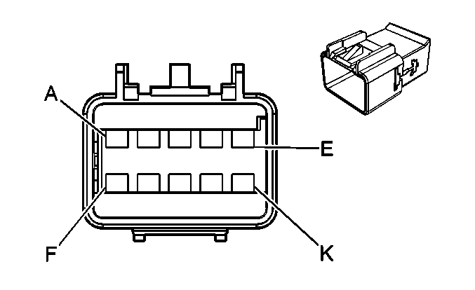
| ||||||||||||||
|---|---|---|---|---|---|---|---|---|---|---|---|---|---|---|---|
Connector Part Information |
| Connector Part Information |
| ||||||||||||
Pin | Wire Color | Circuit No. | Function | Pin | Wire Color | Circuit No. | Function | ||||||||
A | -- | -- | Not Used | A | -- | -- | Not Used | ||||||||
B | PK | 5289 | Adjustable Pedals Position Sensor Signal | B | PK | -- | Adjustable Pedals Position Sensor Signal | ||||||||
C | OG/BK | 5285 | Adjustable Pedals Relay Rearward Control | C | OG/BK | -- | Adjustable Pedals Relay Rearward Control | ||||||||
D | OG | 3040 | Battery Positive Voltage | D | OG | -- | Battery Positive Voltage | ||||||||
E | PU | 5286 | Adjustable Pedals Relay Forward Control | E | PU | -- | Adjustable Pedals Relay Forward Control | ||||||||
F | WH | 5287 | 5-Volt Reference | F | WH | -- | 5-Volt Reference | ||||||||
G | BN/WH | 5288 | Low Reference | G | BN/WH | -- | Low Reference | ||||||||
H | D-GN | 5604 | Adjustable Pedal Relay Rearward Control | H | D-GN | -- | Adjustable Pedal Relay Rearward Control | ||||||||
J | BK | 2250 | Ground | J | BK | -- | Ground | ||||||||
K | TN | 5603 | Adjustable Pedal Relay Forward Control | K | TN | -- | Adjustable Pedal Relay Forward Control | ||||||||

|

| ||||||||||||||
|---|---|---|---|---|---|---|---|---|---|---|---|---|---|---|---|
Connector Part Information |
| Connector Part Information |
| ||||||||||||
Pin | Wire Color | Circuit No. | Function | Pin | Wire Color | Circuit No. | Function | ||||||||
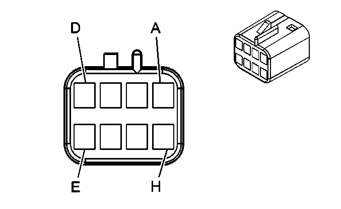
A1 | TN | 3021 | Steering Wheel Module - Stage 1 - High Control | A1 | TN | 3021 | Steering Wheel Module - Stage 1 - High Control | ||||||||
A2 | BN | 3020 | Steering Wheel Module - Stage 1 - Low Control | A2 | BN | 3020 | Steering Wheel Module - Stage 1 - Low Control | ||||||||
B1 | WH | 3023 | Steering Wheel Module - Stage 2 - High Control | B1 | WH | 3023 | Steering Wheel Module - Stage 2 - High Control | ||||||||
B2 | PK | 3022 | Steering Wheel Module - Stage 2 - Low Control | B2 | PK | 3022 | Steering Wheel Module - Stage 2 - Low Control | ||||||||
|
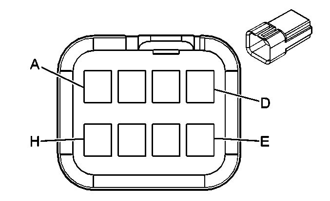
| ||||||||||||||
|---|---|---|---|---|---|---|---|---|---|---|---|---|---|---|---|
Connector Part Information |
| Connector Part Information |
| ||||||||||||
Pin | Wire Color | Circuit No. | Function | Pin | Wire Color | Circuit No. | Function | ||||||||
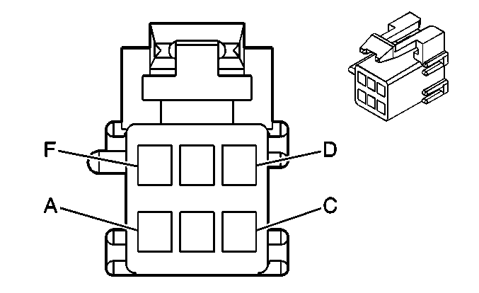
A | YE | 1327 | DIC Fuel Signal (STW) | A | YE | 1327 | DIC Fuel Signal (STW) | ||||||||
B | D-BU | 894 | DIC Toggle Switch Signal (STW) | B | D-BU | 894 | DIC Toggle Switch Signal (STW) | ||||||||
C | PU | 1358 | DIC Switch Signal (STW) | C | D-GN | 1358 | DIC Switch Signal (STW) | ||||||||
D | OG/BK | 1816 | DIC Set/Reset Switch Signal (STW) | D | OG | 1816 | DIC Set/Reset Switch Signal (STW) | ||||||||
E | PK | 2283 | 12-Volt Reference (STW) | E | WH | 2283 | 12-Volt Reference (STW) | ||||||||
F | BN/WH | 230 | Instrument Panel Lamps Dimming Control (STW) | F | BN/WH | 230 | Instrument Panel Lamps Dimming Control (STW) | ||||||||
G | L-GN | 1011 | Remote Radio Control Signal (STW) | G | L-GN | 1011 | Remote Radio Control Signal (STW) | ||||||||
L-GN | 1011 | Remote Radio Control Signal (STW) | |||||||||||||
H | BK | 2250 | Ground (STW) | H | BK | 2250 | Ground (STW) | ||||||||
|
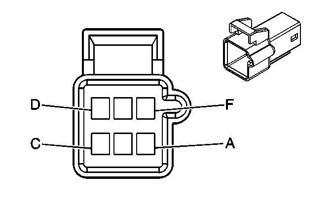
| ||||||||||||||
|---|---|---|---|---|---|---|---|---|---|---|---|---|---|---|---|
Connector Part Information |
| Connector Part Information |
| ||||||||||||
Pin | Wire Color | Circuit No. | Function | Pin | Wire Color | Circuit No. | Function | ||||||||
A | BN/WH | 230 | Instrument Panel Lamps Dimming Control | A | BN/WH | 230 | Instrument Panel Lamps Dimming Control | ||||||||
B | BN | 341 | Ignition 3 Voltage | B | BN | 341 | Ignition 3 Voltage | ||||||||
C | PU/WH | 1382 | LED Dimming Signal | C | PU/WH | 1382 | LED Dimming Signal | ||||||||
D | BN/WH | 1571 | Traction Control Switch Signal | D | BN/WH | 1571 | Traction Control Switch Signal | ||||||||
E | PU | 1681 | Traction Control System Passive Indicator Control | E | PU | 1681 | Traction Control System Passive Indicator Control | ||||||||
F | BK | 2250 | Ground | F | BK | 2250 | Ground | ||||||||

|
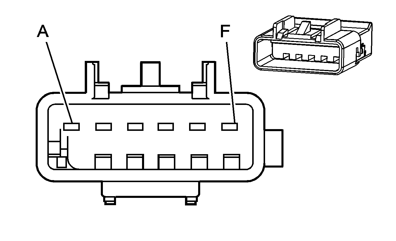
| ||||||||||||||
|---|---|---|---|---|---|---|---|---|---|---|---|---|---|---|---|
Connector Part Information |
| Connector Part Information |
| ||||||||||||
Pin | Wire Color | Circuit No. | Function | Pin | Wire Color | Circuit No. | Function | ||||||||
A | BN/WH | 230 | Instrument Panel Lamps Dimming Control | A | BN/WH | 230 | Instrument Panel Lamps Dimming Control | ||||||||
B | PU/WH | 1382 | LED Dimming Signal/LED Dimming Supply | B | PU/WH | 1382 | LED Dimming Signal/LED Dimming Supply | ||||||||
C | BN/WH | 1571 | Traction Control Switch Signal (NW7) | C | BN/WH | 1571 | Traction Control Switch Signal (NW& | ||||||||
D | WH | 1808 | Service Traction Control Signal (NW7) | D | WH | 1808 | Service Traction Control Signal (NW7) | ||||||||
E | PK | 639 | Ignition 1 Voltage | E | PK | 639 | Ignition 1 Voltage | ||||||||
F | -- | -- | Not Used | F | -- | -- | Not Used | ||||||||
|
| ||||||||||||||
|---|---|---|---|---|---|---|---|---|---|---|---|---|---|---|---|
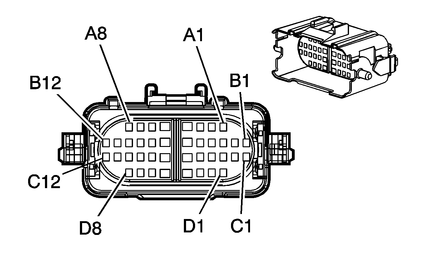
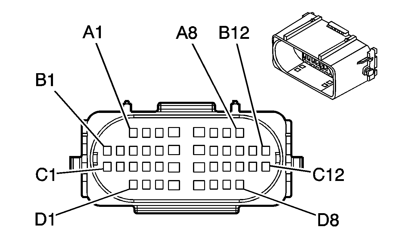
Connector Part Information |
| Connector Part Information |
| ||||||||||||
Pin | Wire Color | Circuit No. | Function | Pin | Wire Color | Circuit No. | Function | ||||||||
A1 | TN | 5458 | Midgate Overhead Console Switch Up Signal (XUV) | A1 | TN | 5458 | Midgate Overhead Console Switch Up Signal (XUV) | ||||||||
PK | 5068 | Intrusion Sensor Switch Disable Signal (BAE) | PK | 5068 | Intrusion Sensor Switch Disable Signal (BAE) | ||||||||||
A2 | L-GN/WH | 2638 | Driver Seat Position Sensor - High | A2 | L-GN/WH | 2638 | Driver Seat Position Sensor - High | ||||||||
A3 | D-GN | 2164 | Side Impact Sensor - Right - Signal (ASF) | A3 | D-GN | 2164 | Side Impact Sensor - Right - Signal (ASF) | ||||||||
A4 | PU | 493 | Rear Seat Audio Enable Signal (UQA) | A4 | PU | 493 | Rear Seat Audio Enable Signal (UQA) | ||||||||
A5 | GY/BK | 2334 | Remote Amplifier Sense Line Signal (UQA) | A5 | GY/BK | 2334 | Remote Amplifier Sense Line Signal (UQA) | ||||||||
A6 | BN | 718 | Low Reference (CJ2) | A6 | BN | 718 | Low Reference (CJ2) | ||||||||
A7 | YE | 1139 | Ignition 1 Voltage | A7 | YE | 1139 | Ignition 1 Voltage | ||||||||
A8 | BK | 751 | Ground | A8 | BK/WH | 751 | Ground | ||||||||
B1 | D-BU | 6252 | Midgate Ajar Indicator Signal (XUV) | B1 | D-BU | 6252 | Midgate Ajar Indicator Signal (XUV) | ||||||||
BN | 5204 | Intrusion Sensor Data Signal (BAE) | BN | 5204 | Intrusion Sensor Data Signal (BAE) | ||||||||||
B2 | PK | 5289 | Adjustable Pedals Position Sensor Signal (JF4) | B2 | PK | 5289 | Adjustable Pedals Position Sensor Signal (JF4) | ||||||||
B3 | D-BU | 1857 | Left Front Midrange Speaker Output (+) (UQA) | B3 | D-BU | 1857 | Left Front Midrange Speaker Output (+) (UQA) | ||||||||
B4 | OG/BK | 2061 | Navigation Mono Audio Signal (-) (UE1) | B4 | OG/BK | 2061 | Navigation Mono Audio Signal (-) (UE1) | ||||||||
PK | 5363 | Inclination Sensor Low Reference (BAE) | PK | 5363 | Inclination Sensor Low Reference (BAE) | ||||||||||
B5 | PK/BK | 2062 | Navigation Mono Audio Signal (+) (UE1) | B5 | PK/BK | 2062 | Navigation Mono Audio Signal (+) (UE1) | ||||||||
L-BU | 5362 | Inclination Sensor Signal (BAE) | L-BU | 5362 | Inclination Sensor Signal (BAE) | ||||||||||
B6 | BN/WH | 5288 | Low Reference (JF4) | B6 | BN/WH | 5288 | Low Reference (JF4) | ||||||||
B7 | PK | 314 | Radio On Signal (UQA) | B7 | PK | 314 | Radio On Signal (UQA) | ||||||||
B8 | WH/BK | 1236 | Inside Air Temperature Sensor Assembly Control (CJ2) | B8 | WH/BK | 1236 | Inside Air Temperature Sensor Assembly Control (CJ2) | ||||||||
B9 | RD | 2484 | Seat Belt Switch Signal - Passenger - Solenoid Reset | B9 | RD | 2484 | Seat Belt Switch Signal - Passenger - Solenoid Reset | ||||||||
B10 | D-GN | 1953 | Right Front Midrange Speaker Output (-) (UQA) | B10 | D-GN | 1953 | Right Front Midrange Speaker Output (-) (UQA) | ||||||||
B11 | D-GN | 1947 | Left Front Low Level Audio Signal (-) (UQA) | B11 | D-GN | 1947 | Left Front Low Level Audio Signal (-) (UQA) | ||||||||
GY | 118 | Left Front Speaker Output (-) (w/o UQA) | GY | 118 | Left Front Speaker Output (-) (w/o UQA) | ||||||||||
B12 | TN | 511 | Left Front Low Level Audio Signal (+) (UQA) | B12 | TN | 511 | Left Front Low Level Audio Signal (+) (UQA) | ||||||||
TN | 201 | Left Front Speaker Output (+) (w/o UQA) | TN | 201 | Left Front Speaker Output (+) (w/o UQA) | ||||||||||
C1 | L-BU | 2645 | Passenger Seat Position - High | C1 | L-BU | 2645 | Passenger Seat Position - High | ||||||||
C2 | D-BU/WH | 2218 | Serial Communications Circuit | C2 | D-BU/WH | 2218 | Serial Communications Circuit | ||||||||
C3 | L-BU | 1957 | Left Front Midrange Speaker Output (-) (UQA) | C3 | L-BU | 1957 | Left Front Midrange Speaker Output (-) (UQA) | ||||||||
C4 | BK/WH | 2644 | Seat Position Sensor Return | C4 | BK/WH | 2644 | Seat Position Sensor Return | ||||||||
C5 | D-GN | 734 | Inside Air Temperature Sensor Signal (CJ2) | C5 | D-GN | 734 | Inside Air Temperature Sensor Signal (CJ2) | ||||||||
C6 | WH | 5287 | 5-Volt Reference (JF4) | C6 | WH | 5287 | 5-Volt Reference (JF4) | ||||||||
C7 | OG | 1853 | Right Front Midrange Speaker Output (+) (UQA) | C7 | OG | 1853 | Right Front Midrange Speaker Output (+) (UQA) | ||||||||
C8 | TN | 2163 | Side Impact Sensor - Right - Voltage (ASF) | C8 | TN | 2163 | Side Impact Sensor - Right - Voltage (ASF) | ||||||||
C9 | D-GN | 5604 | Adjustable Pedal Relay Rearward Control (JF4) | C9 | D-GN | 5604 | Adjustable Pedal Relay Rearward Control (JF4) | ||||||||
C10 | PK | 2306 | Occupant Sensor - Serial Data Link | C10 | PK | 2306 | Occupant Sensor - Serial Data Link | ||||||||
C11 | WH | 2162 | Side Impact Sensor - Left - Signal (ASF) | C11 | WH | 2162 | Side Impact Sensor - Left - Signal (ASF) | ||||||||
C12 | D-BU | 546 | Right Rear Low Level Audio Signal (+) (UQA) | C12 | D-BU | 546 | Right Rear Low Level Audio Signal (+) (UQA) | ||||||||
D-BU | 46 | Right Rear Speaker Output (+) (w/o UQA) | D-BU | 46 | Right Rear Speaker Output (+) (w/o UQA) | ||||||||||
D1 | OG/BK | 1546 | Right Front Low Level Audio Signal (-) (UQA) | D1 | OG/BK | 1546 | Right Front Low Level Audio Signal (-) (UQA) | ||||||||
D-GN | 117 | Right Front Speaker Output (-) (w/o UQA) | D-GN | 117 | Right Front Speaker Output (-) (w/o UQA) | ||||||||||
D2 | TN | 5603 | Adjustable Pedal Relay Forward Control (JF4) | D2 | TN | 5603 | Adjustable Pedal Relay Forward Control (JF4) | ||||||||
D3 | D-GN/WH | 1547 | Rear Low Level Audio Signal (-) (UQA) | D3 | D-GN/WH | 1547 | Rear Low Level Audio Signal (-) (UQA) | ||||||||
YE | 116 | Left Rear Speaker Output (-) (w/o UQA) | YE | 116 | Left Rear Speaker Output (-) (w/o UQA) | ||||||||||
D4 | BK/WH | 238 | Seat Belt Switch - Left | D4 | BK/WH | 238 | Seat Belt Switch - Left | ||||||||
D5 | L-GN | 512 | Right Front Low Level Audio Signal (+) (UQA) | D5 | L-GN | 512 | Right Front Low Level Audio Signal (+) (UQA) | ||||||||
L-GN | 200 | Right Front Speaker Output (+) (w/o UQA) | L-GN | 200 | Right Front Speaker Output (+) (w/o UQA) | ||||||||||
D6 | BN | 599 | Left Rear Low Level Audio Signal (+) (UQA) | D6 | BN | 599 | Left Rear Low Level Audio Signal (+) (UQA) | ||||||||
BN | 199 | Left Rear Speaker Output (+) (w/o UQA) | BN | 199 | Left Rear Speaker Output (+) (w/o UQA) | ||||||||||
D7 | BK | 1946 | Right Rear Low Level Audio Signal (-) (UQA) | D7 | BK | 1946 | Right Rear Low Level Audio Signal (-) (UQA) | ||||||||
L-BU | 115 | Right Rear Speaker Output (-) (w/o UQA) | L-BU | 115 | Right Rear Speaker Output (-) (w/o UQA) | ||||||||||
D8 | YE | 2161 | Side Impact Sensor - Left - Voltage (ASF) | D8 | YE | 2161 | Side Impact Sensor - Left - Voltage (ASF) | ||||||||
|
| ||||||||||||||
|---|---|---|---|---|---|---|---|---|---|---|---|---|---|---|---|
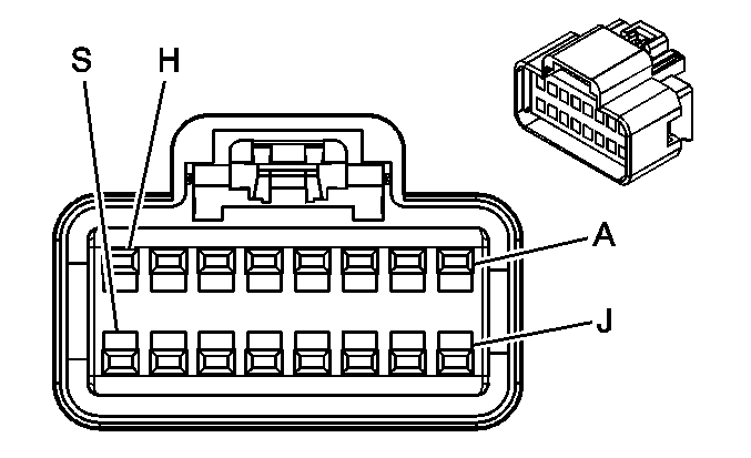
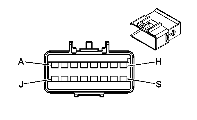
Connector Part Information |
| Connector Part Information |
| ||||||||||||
Pin | Wire Color | Circuit No. | Function | Pin | Wire Color | Circuit No. | Function | ||||||||
A | D-BU | 2575 | Power Window Motor Feed - Right Rear Vent - Close (A34) | A | D-BU | 2575 | Power Window Motor Feed - Right Rear Vent - Close (A34) | ||||||||
B | D-GN | 801 | RAP Fuse Supply Voltage (A34) | B | D-GN | 801 | RAP Fuse Supply Voltage (A34) | ||||||||
C | PU | 2574 | Power Window Motor Feed - Left Rear Vent - Open (A34) | C | PU | 2574 | Power Window Motor Feed - Left Rear Vent - Open (A34) | ||||||||
D | OG | 3140 | Battery Positive Voltage | D | OG | 3140 | Battery Positive Voltage | ||||||||
E | BN/WH | 230 | Instrument Panel Lamps Dimming Control | E | BN/WH | 230 | Instrument Panel Lamps Dimming Control | ||||||||
F | BK | 1350 | Ground | F | BK | 1350 | Ground | ||||||||
G | D-BU | 2573 | Power Window Motor Feed - Left Rear Vent - Close (A34) | G | D-BU | 2573 | Power Window Motor Feed - Left Rear Vent - Close (A34) | ||||||||
H | OG | 110 | Sunroof Switch Close Signal (CF5) | H | OG | 110 | Sunroof Switch Close Signal (CF5) | ||||||||
J | D-BU | 128 | Sunroof Switch Low Reference (CF5) | J | D-BU | 128 | Sunroof Switch Low Reference (CF5) | ||||||||
K | BK | 1150 | Ground (A34) | K | BK | 1150 | Ground (A34) | ||||||||
L | BN | 100 | Sunroof Switch Open Signal (CF5) | L | BN | 100 | Sunroof Switch Open Signal (CF5) | ||||||||
M | GY/BK | 690 | Courtesy Lamp Supply Voltage (DK7) | M | GY/BK | 690 | Courtesy Lamp Supply Voltage (DK7) | ||||||||
N | OG | 1732 | Inadvertent Power Courtesy Lamp Supply Voltage (DK7) | N | OG | 1732 | Inadvertent Power Courtesy Lamp Supply Voltage (DK7) | ||||||||
P | D-GN | 654 | Cellular Microphone Signal (DK7) | P | D-GN | 654 | Cellular Microphone Signal (DK7) | ||||||||
R | GY | 655 | Cellular Microphone Low Reference (DK7) | R | GY | 655 | Cellular Microphone Low Reference (DK7) | ||||||||
S | PU | 2576 | Power Window Motor Feed - Right Rear Vent - Open (A34) | S | PU | 2576 | Power Window Motor Feed - Right Rear Vent - Open (A34) | ||||||||

|

| ||||||||||||||
|---|---|---|---|---|---|---|---|---|---|---|---|---|---|---|---|
Connector Part Information |
| Connector Part Information |
| ||||||||||||
Pin | Wire Color | Circuit No. | Function | Pin | Wire Color | Circuit No. | Function | ||||||||
A | BK | 1350 | Ground | A | BK | 1350 | Ground | ||||||||
B | BN/WH | 230 | Instrument Panel Lamps Dimming Control | B | BN/WH | 230 | Instrument Panel Lamps Dimming Control | ||||||||
C | -- | -- | Not Used | C | -- | -- | Not Used | ||||||||
D | OG | 3140 | Battery Positive Voltage | D | OG | 3140 | Battery Positive Voltage | ||||||||
E-F | -- | -- | Not Used | E-F | -- | -- | Not Used | ||||||||
G | D-GN | 654 | Cellular Microphone Low Reference | G | D-GN | 654 | Cellular Microphone Low Reference | ||||||||
H | GY | 655 | Cellular Microphone Signal | H | GY | 655 | Cellular Microphone Signal | ||||||||
J | GY/BK | 690 | Courtesy Lamp Supply Voltage (DK7) | J | GY/BK | 690 | Courtesy Lamp Supply Voltage (DK7) | ||||||||
K | OG | 1732 | Inadvertent Power Courtesy Lamp Supply Voltage (DK7) | K | OG | 1732 | Inadvertent Power Courtesy Lamp Supply Voltage (DK7) | ||||||||
|
| ||||||||||||||
|---|---|---|---|---|---|---|---|---|---|---|---|---|---|---|---|
Connector Part Information |
| Connector Part Information |
| ||||||||||||
Pin | Wire Color | Circuit No. | Function | Pin | Wire Color | Circuit No. | Function | ||||||||
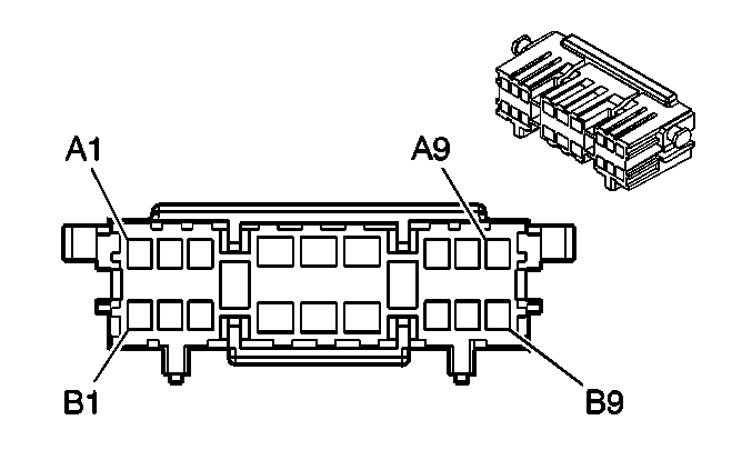
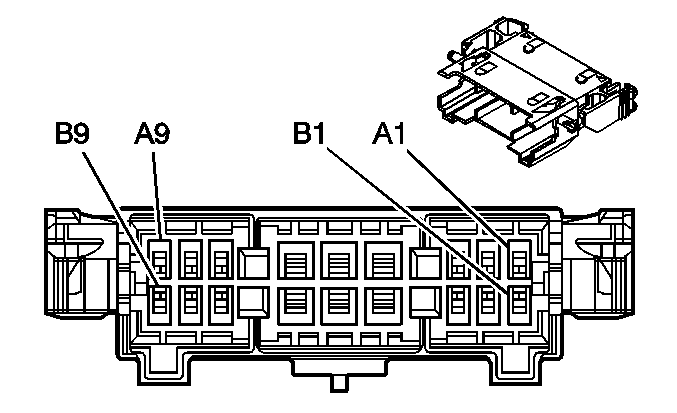
A | BN/WH | 2517 | Keypad Red LED Signal (UE1) | A | BN/WH | 2517 | Keypad Red LED Signal (UE1) | ||||||||
B | YE/BK | 2516 | Keypad Green LED Signal (UE1) | B | YE/BK | 2516 | Keypad Green LED Signal (UE1) | ||||||||
C | D-GN/WH | 2514 | Keypad Signal (UE1) | C | D-GN/WH | 2514 | Keypad Signal (UE1) | ||||||||
D | L-GN/BK | 2515 | Keypad Supply Voltage (UE1) | D | L-GN/BK | 2515 | Keypad Supply Voltage (UE1) | ||||||||
E | GY | 655 | Cellular Microphone Signal (XUV w/UE1) | E | GY | 655 | Cellular Microphone Signal (XUV w/UE1) | ||||||||
D-GN | 654 | Cellular Microphone Signal (Except XUV w/UE1) | D-GN | 654 | Cellular Microphone Signal (Except XUV w/UE1) | ||||||||||
F | D-GN | 654 | Cellular Microphone Low Reference (XUV w/UE1) | F | D-GN | 654 | Cellular Microphone Low Reference (XUV w/UE1) | ||||||||
GY | 655 | Cellular Microphone Low Reference (Except XUV w/UE1) | GY | 655 | Cellular Microphone Low Reference (Except XUV w/UE1) | ||||||||||
G | BK/WH | 372 | Audio Common (U42) | G | BK/WH | 372 | Audio Common (U42) | ||||||||
D-GN | 5437 | Audio Common (XUV w/U42) | |||||||||||||
H | L-GN | 5438 | Endgate Overhead Console Switch Down Signal (XUV) | H | L-GN | 5438 | Endgate Overhead Console Switch Down Signal (XUV) | ||||||||
D-GN/WH | 368 | Right Audio Signal (+) (U42) | D-GN/WH | 368 | Right Audio Signal (+) (U42) | ||||||||||
J | YE | 5439 | Endgate Overhead Console Switch Up Signal (XUV) | J | YE | 5439 | Endgate Overhead Console Switch Up Signal (XUV) | ||||||||
BN/WH | 367 | Left Audio Signal (+) (U42) | BN/WH | 367 | Left Audio Signal (+) (U42) | ||||||||||
K | WH | 5457 | Midgate Overhead Console Switch Down Signal (XUV) | K | WH | 5457 | Midgate Overhead Console Switch Down Signal (XUV) | ||||||||
YE/BK | 5485 | Class 2 Serial Data (Except XUV w/U42) | YE/BK | 5485 | Class 2 Serial Data (Except XUV) | ||||||||||
L | TN | 5458 | Midgate Overhead Console Switch Up Signal (XUV) | L | TN | 5458 | Midgate Overhead Console Switch Up Signal (XUV) | ||||||||
BN/WH | 2609 | Park Lamps Supply Voltage (Y92) | BN/WH | 2609 | Park Lamps Supply Voltage (Y92) | ||||||||||
M | D-BU | 5435 | Rear Movable Roof Switch Open Signal (XUV) | M | D-BU | 5435 | Rear Movable Roof Switch Open Signal (XUV) | ||||||||
GY/BK | 690 | Courtesy Lamp Supply Voltage (Y92) | GY/BK | 690 | Courtesy Lamp Supply Voltage (Y92) | ||||||||||
N | L-BU | 5436 | Rear Movable Roof Switch Close Signal (XUV) | N | L-BU | 5436 | Rear Movable Roof Switch Close Signal (XUV) | ||||||||
OG | 1732 | Courtesy Lamps Supply Voltage (Y92) | OG | 1732 | Courtesy Lamps Supply Voltage (Y92) | ||||||||||
P | GY/BK | 690 | Courtesy Lamps Supply Voltage (XUV) | P | GY/BK | 690 | Courtesy Lamps Supply Voltage (XUV) | ||||||||
R | GY/BK | 1798 | Ground (XUV) | R | GY/BK | 1798 | Ground (XUV) | ||||||||
S | OG | 3440 | Battery Positive Voltage (XUV) | S | OG | 3440 | Battery Positive Voltage (XUV) | ||||||||
|
| ||||||||||||||
|---|---|---|---|---|---|---|---|---|---|---|---|---|---|---|---|
Connector Part Information |
| Connector Part Information |
| ||||||||||||
Pin | Wire Color | Circuit No. | Function | Pin | Wire Color | Circuit No. | Function | ||||||||
A1 | BK | 1946 | Right Rear Low Level Audio Signal (-) (UK6) | A1 | BK | 1946 | Right Rear Low Level Audio Signal (-) | ||||||||
A2 | YE | 2277 | Auxiliary HVAC Enable Control (CJ3) | A2 | YE | 2277 | Auxiliary HVAC Enable Control (CJ3) | ||||||||
A3 | BN/WH | 230 | Instrument Panel Lamps Dimming Control | A3 | BN/WH | 230 | Instrument Panel Lamps Dimming Control | ||||||||
A4 | BN | 341 | Ignition 3 Voltage (W49 w/NW7) | A4 | BN | 341 | Ignition 3 Voltage | ||||||||
BN | 341 | Ignition 3 Voltage (Short Wheel Base/XUV) | |||||||||||||
BN | 341 | Ignition 3 Voltage (Short Wheel Base w/CJ3) | |||||||||||||
A5 | OG | 1040 | Battery Positive Voltage | A5 | OG | 1040 | Battery Positive Voltage | ||||||||
A6 | BK | 2250 | Ground | A6 | BK | 2250 | Ground | ||||||||
A7 | GY | 2289 | Rear HVAC/Audio Class 2 Serial Data | A7 | GY | 2289 | Rear HVAC/Audio Class 2 Serial Data | ||||||||
A8 | BN | 599 | Left Rear Low Level Audio Signal (+) (UK6) | A8 | BN/WH | 599 | Left Rear Low Level Audio Signal (+) (UK6) | ||||||||
A9 | D-BU | 546 | Right Rear Low Level Audio Signal (+) (UK6) | A9 | D-BU | 546 | Right Rear Low Level Audio Signal (+) | ||||||||
B1 | BN | 199 | Left Rear Speaker Output (+) (UK6) | B1 | BN | 199 | Left Rear Speaker Output (+) | ||||||||
B2 | D-BU | 46 | Right Rear Speaker Output (+) (UK6) | B2 | D-BU | 46 | Right Rear Speaker Output (+) | ||||||||
B3 | BN | 1547 | Left Rear Low Level Audio Signal (-) (UK6) | B3 | D-GN/WH | 1547 | Left Rear Low Level Audio Signal (-) (UK6) | ||||||||
B4 | OG | 4340 | Battery Positive Voltage (Except Short Wheel Base w/CJ3) | B4 | OG | 4340 | Battery Positive Voltage (Except Short Wheel Base w/CJ3) | ||||||||
B5 | YE | 116 | Left Rear Speaker Output (-) (UK6) | B5 | YE | 116 | Left Rear Speaker Output (-) | ||||||||
B6 | L-BU | 115 | Right Rear Speaker Output (-) (UK6) | B6 | L-BU | 115 | Right Rear Speaker Output (-) | ||||||||
B7 | D-GN | 2347 | Auxiliary Blower Motor High Speed Control (CJ2) | B7 | D-GN | 2347 | Auxiliary Blower Motor High Speed Control (CJ2) | ||||||||
B8 | -- | -- | Not Used | B8 | -- | -- | Not Used | ||||||||
B9 | D-BU | 2348 | Auxiliary Blower Motor Medium Speed Control (CJ2) | B9 | D-BU | 2348 | Auxiliary Blower Motor Medium Speed Control (CJ2) | ||||||||
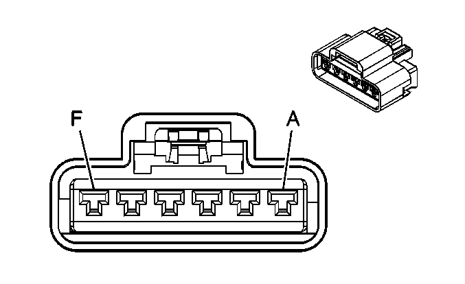
|
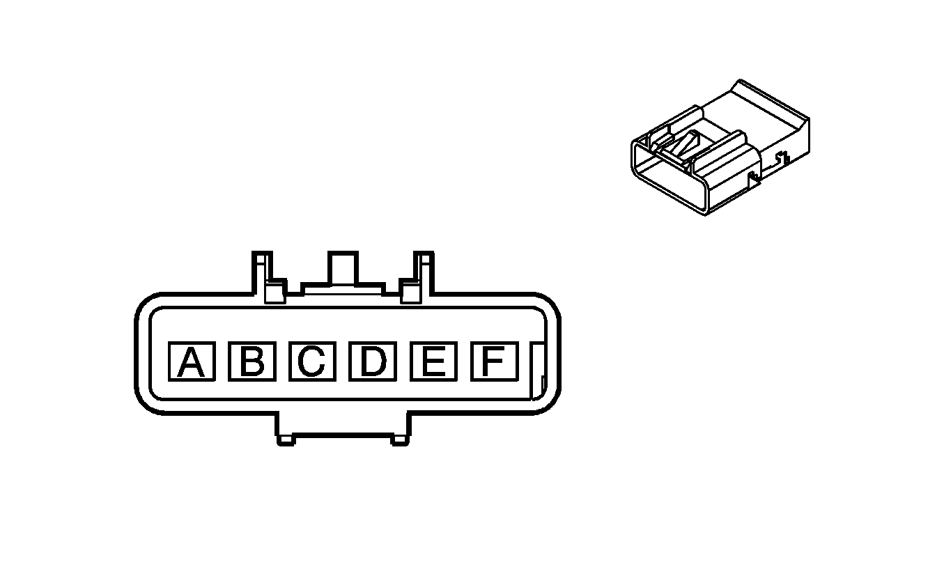
| ||||||||||||||
|---|---|---|---|---|---|---|---|---|---|---|---|---|---|---|---|
Connector Part Information |
| Connector Part Information |
| ||||||||||||
Pin | Wire Color | Circuit No. | Function | Pin | Wire Color | Circuit No. | Function | ||||||||
A | BK | 1150 | Ground | A | BK/PU | 1150 | Ground | ||||||||
B | OG | 1840 | Battery Positive Voltage (XUV w/CF5) | B | YE/RD | 1840 | Battery Positive Voltage (CF5) | ||||||||
OG | 1740 | Battery Positive Voltage (Except XUV w/CF5) | |||||||||||||
C | D-BU | 128 | Sunroof Switch Low Reference | C | BN | 128 | Sunroof Switch Low Reference | ||||||||
D | BN | 100 | Sunroof Switch Open Signal | D | WH | 100 | Sunroof Switch Open Signal | ||||||||
E | OG | 110 | Sunroof Switch Close Signal | E | L-BU | 110 | Sunroof Switch Close Signal | ||||||||
F | D-BU | 1353 | RAP Supply Voltage (Short Wheel Base/XUV) | F | PU | 1353 | RAP Supply Voltage | ||||||||
D-GN | 801 | RAP Supply Voltage (Long Wheel Base Except XUV) | |||||||||||||

|

| ||||||||||||||
|---|---|---|---|---|---|---|---|---|---|---|---|---|---|---|---|
Connector Part Information |
| Connector Part Information |
| ||||||||||||
Pin | Wire Color | Circuit No. | Function | Pin | Wire Color | Circuit No. | Function | ||||||||
A | GY | 2598 | Low Reference | A | GY | 2598 | Low Reference | ||||||||
B | D-BU | 1199 | Auxiliary Air Temp Door Position Signal | B | D-BU | 1199 | Auxiliary Air Temp Door Position Signal | ||||||||
C | YE | 2214 | Auxiliary Air Temp Door Control | C | YE | 2214 | Auxiliary Air Temp Door Control | ||||||||
D | GY | 2599 | Auxiliary Mode Door Control | D | GY | 2599 | Auxiliary Mode Door Control | ||||||||
E | RD | 2600 | Auxiliary Actuator Door Control | E | RD | 2600 | Auxiliary Actuator Door Control | ||||||||
F | BN/WH | 2601 | Auxiliary Mode Door Position Signal | F | BN/WH | 2601 | Auxiliary Mode Door Position Signal | ||||||||
G | GY | 598 | 5-Volt Reference | G | GY | 598 | 5-Volt Reference | ||||||||
H | -- | -- | Not Used | H | GY | 2603 | TXV Solenoid Control - Not Equipped | ||||||||
J | -- | -- | Not Used | J | -- | -- | Not Used | ||||||||
K | GY | 2604 | Auxiliary Blower Motor Speed Control | K | GY | 2604 | Auxiliary Blower Motor Speed Control | ||||||||
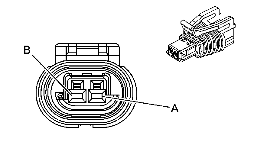
|
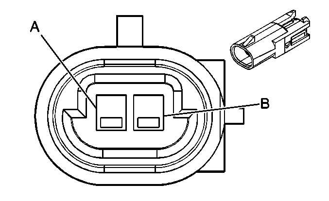
| ||||||||||||||
|---|---|---|---|---|---|---|---|---|---|---|---|---|---|---|---|
Connector Part Information |
| Connector Part Information |
| ||||||||||||
Pin | Wire Color | Circuit No. | Function | Pin | Wire Color | Circuit No. | Function | ||||||||
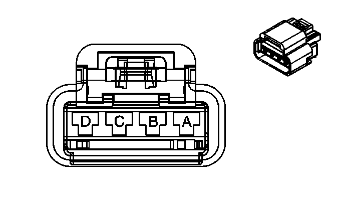
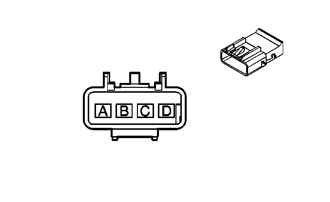
A | L-GN/BK | 822 | VSS Low Signal | A | L-GN/BK | 822 | VSS Low Signal | ||||||||
B | PU/WH | 821 | VSS High Signal | B | PU/WH | 821 | VSS High Signal | ||||||||
|
| ||||||||||||||
|---|---|---|---|---|---|---|---|---|---|---|---|---|---|---|---|
Connector Part Information |
| Connector Part Information |
| ||||||||||||
Pin | Wire Color | Circuit No. | Function | Pin | Wire Color | Circuit No. | Function | ||||||||
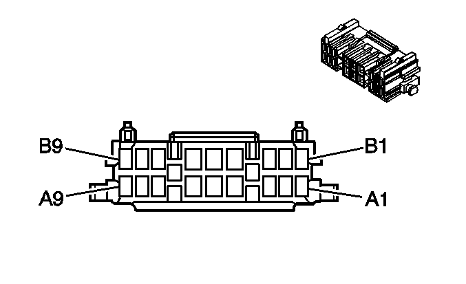
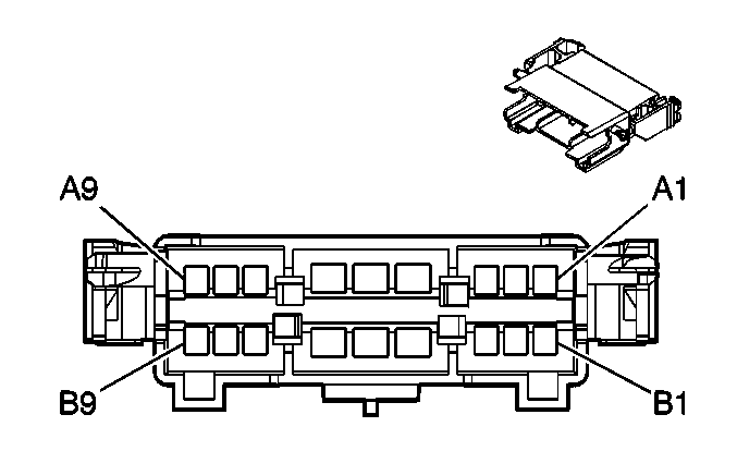
A | BK/WH | 2644 | Seat Position Sensor Return | A | BK/WH | 2644 | Seat Position Sensor Return | ||||||||
B | -- | -- | Not Used | B | -- | -- | Not Used | ||||||||
C | L-GN/WH | 2638 | Driver Seat Position Sensor - High | C | L-GN/WH | 2638 | Driver Seat Position Sensor - High | ||||||||
D | BK/WH | 238 | Seat Belt Switch - Left | D | BK/WH | 238 | Seat Belt Switch - Left | ||||||||
|
| ||||||||||||||
|---|---|---|---|---|---|---|---|---|---|---|---|---|---|---|---|
Connector Part Information |
| Connector Part Information |
| ||||||||||||
Pin | Wire Color | Circuit No. | Function | Pin | Wire Color | Circuit No. | Function | ||||||||
A1 | TN | 2481 | Passenger Heated Seat Back Element Supply Voltage (KA1) | A1 | TN | 2481 | Passenger Heated Seat Back Element Supply Voltage (KA1) | ||||||||
A2 | PK | 2480 | Passenger Heated Seat Element Control (KA1) | A2 | PK | 2480 | Passenger Heated Seat Element Control (KA1) | ||||||||
A3 | D-BU | 2479 | Passenger Heated Seat Element Supply Voltage (KA1) | A3 | BK | 2479 | Passenger Heated Seat Element Supply Voltage (KA1) | ||||||||
A4 | BK | 1350 | Ground | A4 | BK | 1350 | Ground | ||||||||
A5 | -- | -- | Not Used | A5 | -- | -- | Not Used | ||||||||
A6 | OG | 3450 | Battery Positive Voltage (AR9) | A6 | OG | 3450 | Battery Positive Voltage (AR9) | ||||||||
A7 | L-BU | 5476 | Passenger Heated Seat Back Low Reference (KA1) | A7 | D-GN | 5476 | Passenger Heated Seat Back Low Reference (KA1) | ||||||||
A8 | BK/WH | 2644 | Seat Position Sensor Return | A8 | BK | 2644 | Seat Position Sensor Return | ||||||||
A9 | D-BU | 5475 | Passenger Heated Seat Back Temperature Sensor Signal (KA1) | A9 | D-BU | 5475 | Passenger Heated Seat Back Temperature Sensor Signal (KA1) | ||||||||
B1 | BK/WH | 238 | Seat Belt Switch - Left | B1 | BK/WH | 238 | Seat Belt Switch - Left | ||||||||
B2 | L-GN/WH | 2638 | Driver Seat Position Sensor - High | B2 | BK | 2638 | Driver Seat Position Sensor - High | ||||||||
B3 | BN/WH | 5288 | Low Reference (JF4) | B3 | BK | 5288 | Low Reference (JF4) | ||||||||
B4 | WH | 5287 | 5-Volt Reference (JF4) | B4 | OG | 5287 | 5-Volt Reference (JF4) | ||||||||
B5 | D-GN | 5604 | Adjustable Pedal Relay Rearward Control (JF4) | B5 | TN | 5604 | Adjustable Pedal Relay Rearward Control (JF4) | ||||||||
B6 | TN | 5603 | Adjustable Pedal Relay Forward Control (JF4) | B6 | YE | 5603 | Adjustable Pedal Relay Forward Control (JF4) | ||||||||
B7 | PK | 5289 | Adjustable Pedals Position Sensor Signal (JF4) | B7 | BK | 5289 | Adjustable Pedals Position Sensor Signal (JF4) | ||||||||
B8 | OG | 2740 | Battery Positive Voltage (AR9) | B8 | OG | 2740 | Battery Positive Voltage (AR9) | ||||||||
B9 | BN/WH | 1048 | SCM (Seat) Class 2 Serial Data (AAB) | B9 | BK | 1048 | SCM (Seat) Class 2 Serial Data (AAB) | ||||||||
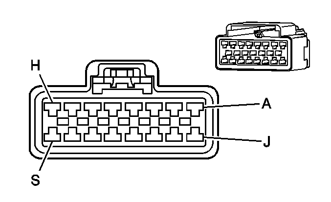
|
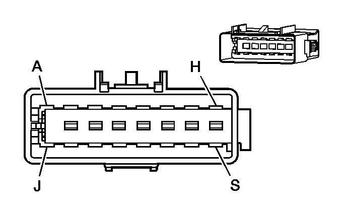
| ||||||||||||||
|---|---|---|---|---|---|---|---|---|---|---|---|---|---|---|---|
Connector Part Information |
| Connector Part Information |
| ||||||||||||
Pin | Wire Color | Circuit No. | Function | Pin | Wire Color | Circuit No. | Function | ||||||||
A | BK | 1450 | Ground (V40) | A | BK | 1450 | Ground (V40) | ||||||||
B | L-BU | 5476 | Passenger Heated Seat Back Low Reference (KA1) | B | GY | 5476 | Passenger Heated Seat Back Low Reference (KA1) | ||||||||
C | PK | 2480 | Passenger Heated Seat Element Control (KA1) | C | BK | 2480 | Passenger Heated Seat Element Control (KA1) | ||||||||
D | D-BU | 5475 | Passenger Heated Seat Back Temperature Sensor Signal (KA1) | D | BN | 5475 | Passenger Heated Seat Back Temperature Sensor Signal (KA1) | ||||||||
E | TN | 2481 | Passenger Heated Seat Back Element Supply Voltage (KA1) | E | TN | 2481 | Passenger Heated Seat Back Element Supply Voltage (KA1) | ||||||||
F | OG | 3450 | Battery Positive Voltage (V40) | F | OG | 3450 | Battery Positive Voltage (V40) | ||||||||
G | D-BU | 2479 | Passenger Heated Seat Element Supply Voltage (KA1) | G | BK | 2479 | Passenger Heated Seat Element Supply Voltage (KA1) | ||||||||
H | BK/WH | 2644 | Seat Position Sensor Return | H | BK | 2644 | Seat Position Sensor Return | ||||||||
J | L-BU | 2645 | Passenger Seat Position - High | J | BK | 2645 | Passenger Seat Position - High | ||||||||
K | RD | 2484 | Seat Belt Switch Signal - Passenger - Solenoid Reset | K | BK | 2484 | Seat Belt Switch Signal - Passenger - Solenoid Reset | ||||||||
L | D-BU | 2307 | Passenger Air Bag On Indicator Control (AL0) | L | D-BU | 2307 | Passenger Air Bag On Indicator Control (AL0) | ||||||||
M | YE | 1139 | Ignition 1 Voltage | M | YE | 1139 | Ignition 1 Voltage | ||||||||
N | D-GN | 2308 | Passenger Air Bag Off Indicator Control (AL0) | N | D-GN | 2308 | Passenger Air Bag Off Indicator Control (AL0) | ||||||||
P | PK | 2306 | Occupant Sensor - Serial Data Link | P | PK | 2306 | Occupant Sensor - Serial Data Link | ||||||||
R | BK | 751 | Ground | R | BK/WH | 751 | Ground | ||||||||
S | -- | -- | Not Used | S | -- | -- | Not Used | ||||||||
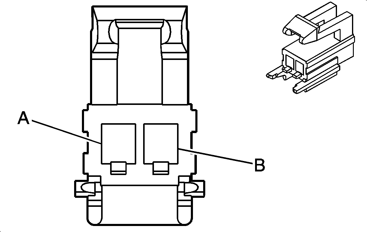
|
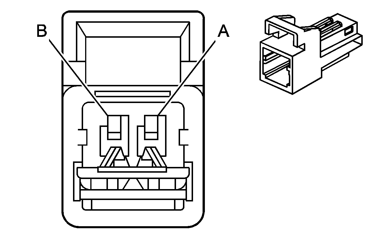
| ||||||||||||||
|---|---|---|---|---|---|---|---|---|---|---|---|---|---|---|---|
Connector Part Information |
| Connector Part Information |
| ||||||||||||
Pin | Wire Color | Circuit No. | Function | Pin | Wire Color | Circuit No. | Function | ||||||||
A | OG/BK | 2119 | Seat Belt Pretensioner - Left - Low Control | A | OG/BK | 2119 | Seat Belt Pretensioner - Left - Low Control | ||||||||
B | BK/WH | 2118 | Seat Belt Pretensioner - Left - High Control | B | BK/WH | 2118 | Seat Belt Pretensioner - Left - High Control | ||||||||

|

| ||||||||||||||
|---|---|---|---|---|---|---|---|---|---|---|---|---|---|---|---|
Connector Part Information |
| Connector Part Information |
| ||||||||||||
Pin | Wire Color | Circuit No. | Function | Pin | Wire Color | Circuit No. | Function | ||||||||
A | OG | 2117 | Seat Belt Pretensioner - Right - Low Control | A | OG | 2117 | Seat Belt Pretensioner - Right - Low Control | ||||||||
B | L-GN | 2116 | Seat Belt Pretensioner - Right - High Control | B | L-GN | 2116 | Seat Belt Pretensioner - Right - High Control | ||||||||
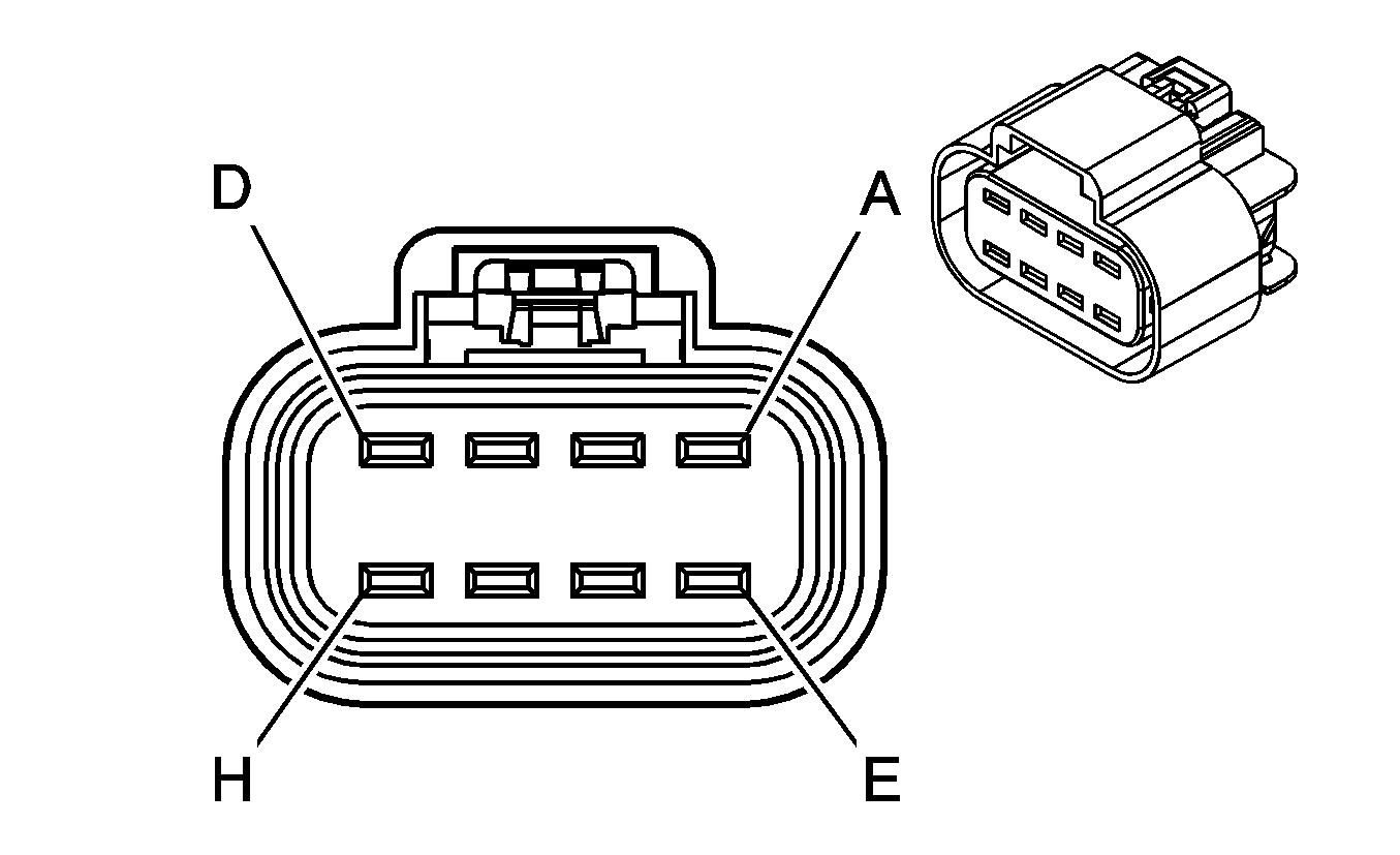
|
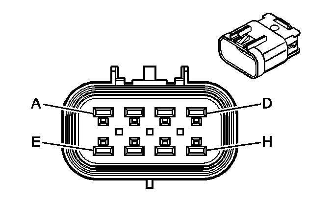
| ||||||||||||||
|---|---|---|---|---|---|---|---|---|---|---|---|---|---|---|---|
Connector Part Information |
| Connector Part Information |
| ||||||||||||
Pin | Wire Color | Circuit No. | Function | Pin | Wire Color | Circuit No. | Function | ||||||||
A | OG | 3440 | Battery Positive Voltage | A | OG | 3440 | Battery Positive Voltage | ||||||||
B | BK | 1150 | Ground | B | BK | 1150 | Ground | ||||||||
C | WH/BK | 5457 | Midgate Overhead Console Switch Down Signal | C | WH/BK | 5457 | Midgate Overhead Console Switch Down Signal | ||||||||
D | TN | 5458 | Midgate Overhead Console Switch Up Signal | D | TN | 5458 | Midgate Overhead Console Switch Up Signal | ||||||||
E | OG | 2440 | Battery Positive Voltage | E | OG | 2440 | Battery Positive Voltage | ||||||||
F | D-BU | 5601 | Midgate Relay Coil Control | F | D-BU | 5601 | Midgate Relay Coil Control | ||||||||
G | D-BU | 6252 | Midgate Ajar Indicator Signal | G | D-BU | 6252 | Midgate Ajar Indicator Signal | ||||||||
H | -- | -- | Not Used | H | -- | -- | Not Used | ||||||||

|

| ||||||||||||||
|---|---|---|---|---|---|---|---|---|---|---|---|---|---|---|---|
Connector Part Information |
| Connector Part Information |
| ||||||||||||
Pin | Wire Color | Circuit No. | Function | Pin | Wire Color | Circuit No. | Function | ||||||||
A | GY | 2537 | Cargo Release Switch Signal | A | BU | 2537 | Cargo Release Switch Signal | ||||||||
B | D-GN | 5437 | Audio Common | B | GN | 5437 | Audio Common | ||||||||
C | L-GN | 5438 | Endgate Overhead Console Switch Down Signal | C | L-GN | 5438 | Endgate Overhead Console Switch Down Signal | ||||||||
D | YE | 5439 | Endgate Overhead Console Switch Up Signal | D | YE | 5439 | Endgate Overhead Console Switch Up Signal | ||||||||
E | OG | 3340 | Battery Positive Voltage | E | GY | 3340 | Battery Positive Voltage | ||||||||
F | PU | 5513 | Class 2 Serial Data | F | OG | 932 | Class 2 Serial Data | ||||||||
G | D-BU | 5435 | Rear Movable Roof Switch Open Signal | G | PU | 5435 | Rear Movable Roof Switch Open Signal | ||||||||
H | L-BU | 5436 | Rear Movable Roof Switch Close Signal | H | RD | 5436 | Rear Movable Roof Switch Close Signal | ||||||||
J | GY/BK | 1798 | Low Reference | J | YE | 1798 | Low Reference | ||||||||
K | -- | -- | Not Used | K | -- | -- | Not Used | ||||||||
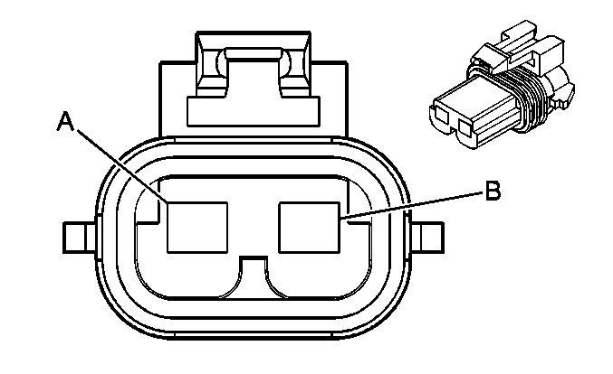
|
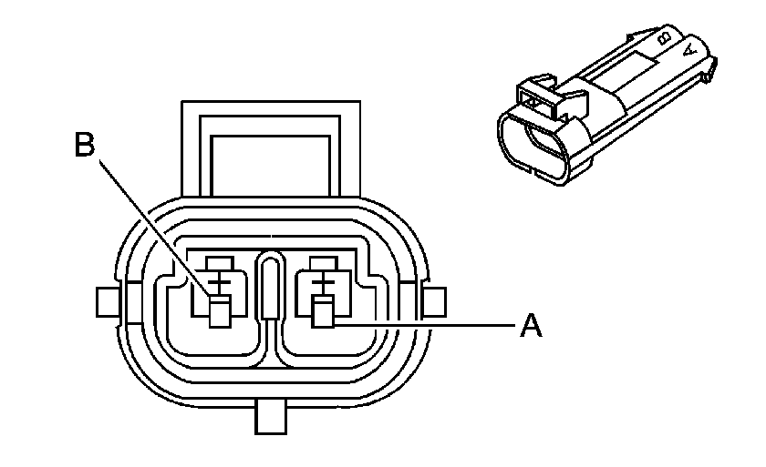
| ||||||||||||||
|---|---|---|---|---|---|---|---|---|---|---|---|---|---|---|---|
Connector Part Information |
| Connector Part Information |
| ||||||||||||
Pin | Wire Color | Circuit No. | Function | Pin | Wire Color | Circuit No. | Function | ||||||||
A | OG | 2640 | Battery Positive Voltage | A | GN | 2640 | Battery Positive Voltage | ||||||||
B | BK | 1150 | Ground | B | BK | 1150 | Ground | ||||||||
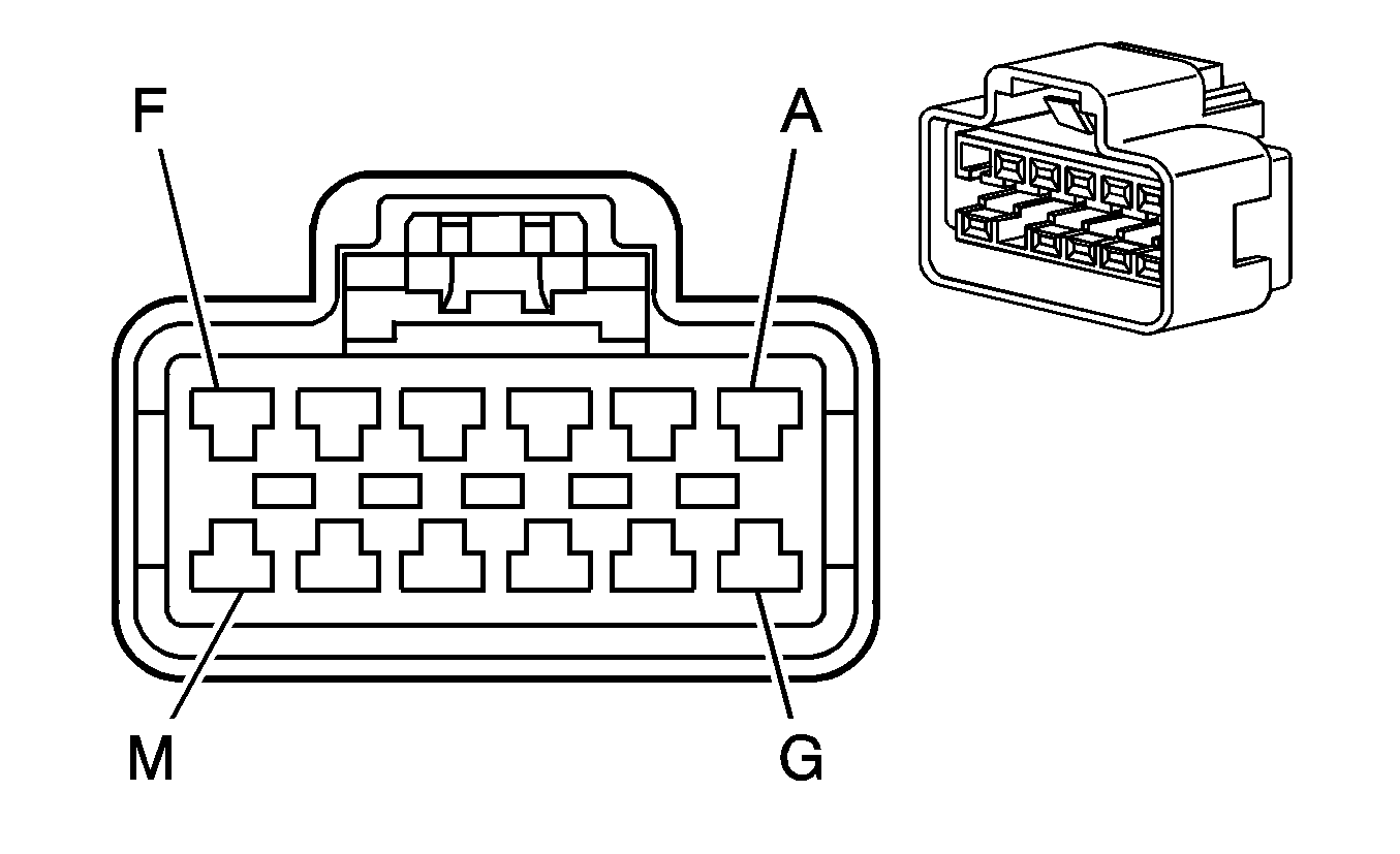
|
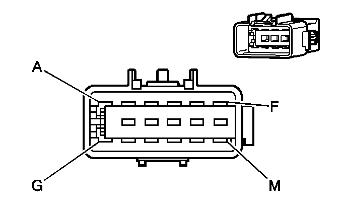
| ||||||||||||||
|---|---|---|---|---|---|---|---|---|---|---|---|---|---|---|---|
Connector Part Information |
| Connector Part Information |
| ||||||||||||
Pin | Wire Color | Circuit No. | Function | Pin | Wire Color | Circuit No. | Function | ||||||||
A | RD | 2600 | Auxiliary Actuator Door Control | A | RD | 2600 | Auxiliary Actuator Door Control | ||||||||
RD | 2600 | Auxiliary Actuator Door Control | |||||||||||||
B | YE | 2214 | Auxiliary Air Temperature Door Control | B | YE | 2214 | Auxiliary Air Temperature Door Control | ||||||||
C | -- | -- | Not Used | C | -- | -- | Not Used | ||||||||
D | BK | 1650 | Ground | D | BK | 1650 | Ground | ||||||||
E | OG | 840 | Battery Positive Voltage | E | OG | 840 | Battery Positive Voltage | ||||||||
F | GY | 598 | 5-Volt Reference | F | GY/BK | 598 | 5-Volt Reference | ||||||||
GY/BK | 598 | 5-Volt Reference | |||||||||||||
G | GY | 2604 | Auxiliary Blower Motor Speed Control | G | GY | 2604 | Auxiliary Blower Motor Speed Control | ||||||||
H | BN/WH | 2601 | Auxiliary Mode Door Position Signal | H | BN/WH | 2601 | Auxiliary Mode Door Position Signal | ||||||||
J | D-BU | 1199 | Auxiliary Air Temperature Door Position Signal | J | D-BU | 1199 | Auxiliary Air Temperature Door Position Signal | ||||||||
K | GY | 2599 | Auxiliary Mode Door Control | K | GY/WH | 2599 | Auxiliary Mode Door Control | ||||||||
L | GY | 2598 | Low Reference | L | GY/RD | 2598 | Low Reference | ||||||||
GY/RD | 2598 | Low Reference | |||||||||||||
M | -- | -- | Not Used | M | -- | -- | Not Used | ||||||||
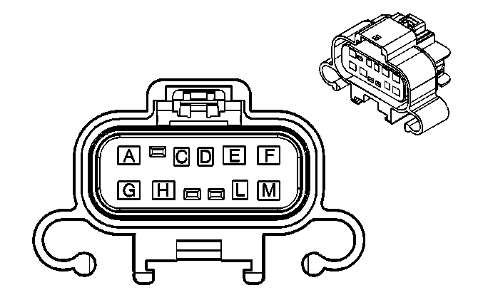
|
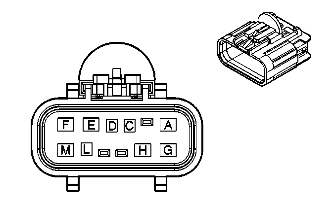
| ||||||||||||||
|---|---|---|---|---|---|---|---|---|---|---|---|---|---|---|---|
Connector Part Information |
| Connector Part Information |
| ||||||||||||
Pin | Wire Color | Circuit No. | Function | Pin | Wire Color | Circuit No. | Function | ||||||||
A | GY | 118 | Left Front Speaker Output (-) | A | GY | 118 | Left Front Speaker Output (-) | ||||||||
B | -- | -- | Not Used | B | -- | -- | Not Used | ||||||||
C | L-BU | 2114 | Left Turn Signal Lamps Supply Voltage | C | L-BU | 2114 | Left Turn Signal Lamps Supply Voltage | ||||||||
D | YE | 2161 | Side Impact Sensor - Left - Voltage (ASF) | D | YE | 2161 | Side Impact Sensor - Left - Voltage (ASF) | ||||||||
E | WH | 2162 | Side Impact Sensor - Left - Signal (ASF) | E | WH | 2162 | Side Impact Sensor - Left - Signal (ASF) | ||||||||
F | OG | 1240 | Battery Positive Voltage | F | OG | 1240 | Battery Positive Voltage | ||||||||
G | TN | 201 | Left Front Speaker Output (+) | G | TN | 201 | Left Front Speaker Output (+) | ||||||||
H | BN | 1046 | DDM Class 2 Serial Data | H | BN | 1046 | DDM Class 2 Serial Data | ||||||||
J-K | -- | -- | Not Used | J-K | -- | -- | Not Used | ||||||||
L | OG | 4140 | Battery Positive Voltage | L | OG | 4140 | Battery Positive Voltage | ||||||||
M | BK | 1350 | Ground | M | BK | 1350 | Ground | ||||||||

|

| ||||||||||||||
|---|---|---|---|---|---|---|---|---|---|---|---|---|---|---|---|
Connector Part Information |
| Connector Part Information |
| ||||||||||||
Pin | Wire Color | Circuit No. | Function | Pin | Wire Color | Circuit No. | Function | ||||||||
A | OG | 1340 | Battery Positive Voltage | A | OG | 1340 | Battery Positive Voltage | ||||||||
B | -- | -- | Not Used | B | -- | -- | Not Used | ||||||||
C | D-BU | 2115 | Right Turn Signal Lamps Supply Voltage | C | D-BU | 2115 | Right Turn Signal Lamps Supply Voltage | ||||||||
D | TN | 2163 | Side Impact Sensor - Right - Voltage (ASF) | D | TN | 2163 | Side Impact Sensor - Right - Voltage (ASF) | ||||||||
E | D-GN | 2164 | Side Impact Sensor - Right - Signal (ASF) | E | D-GN | 2164 | Side Impact Sensor - Right - Signal (ASF) | ||||||||
F | L-GN | 200 | Right Front Speaker Output (+) | F | L-GN | 200 | Right Front Speaker Output (+) | ||||||||
G | BK | 1450 | Ground | G | BK | 1450 | Ground | ||||||||
H | TN | 1047 | PDM Class 2 Serial Data | H | TN | 1047 | PDM Class 2 Serial Data | ||||||||
J-K | -- | -- | Not Used | J-K | -- | -- | Not Used | ||||||||
L | OG | 4240 | Battery Positive Voltage | L | OG | 4240 | Battery Positive Voltage | ||||||||
M | D-GN | 117 | Right Front Speaker Output (-) | M | D-GN | 117 | Right Front Speaker Output (-) | ||||||||
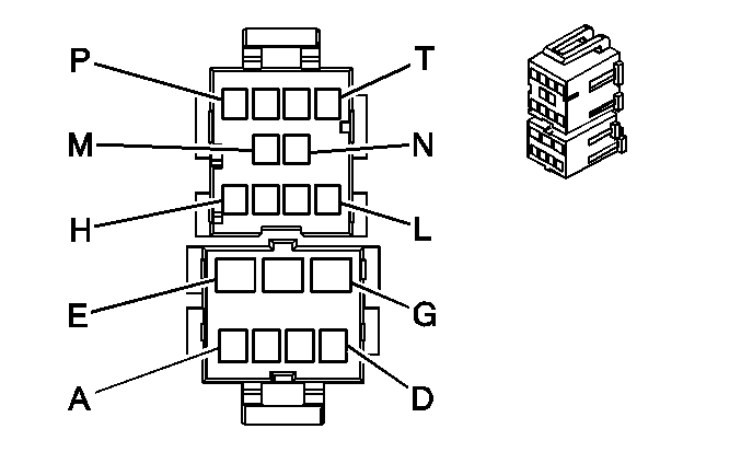
|
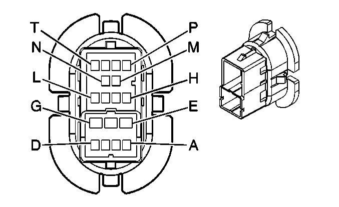
| ||||||||||||||||||
|---|---|---|---|---|---|---|---|---|---|---|---|---|---|---|---|---|---|---|---|
Connector Part Information |
| Connector Part Information |
| ||||||||||||||||
Pin | Wire Color | Circuit No. | Function | Pin | Wire Color | Circuit No. | Function | ||||||||||||
A | L-BU/BK | 747 | Left Rear Door Ajar Switch Signal | A | L-BU/BK | 747 | Left Rear Door Ajar Switch Signal | ||||||||||||
B | WH | 1185 | Power Window Switch Left Rear Up Signal | B | WH | 1185 | Power Window Switch Left Rear Up Signal | ||||||||||||
C | YE | 1187 | Power Window Switch Left Rear Down Signal | C | YE | 1187 | Power Window Switch Left Rear Down Signal | ||||||||||||
D | -- | -- | Not Used | D | -- | -- | Not Used | ||||||||||||
E | OG | 1240 | Battery Positive Voltage | E | OG | 1240 | Battery Positive Voltage | ||||||||||||
F | -- | -- | Not Used | F | -- | -- | Not Used | ||||||||||||
G | BK | 1350 | Ground | G | BK | 1350 | Ground | ||||||||||||
H | L-BU | 2265 | Power Window Lockout Left Rear Control | H | L-BU | 2265 | Power Window Lockout Left Rear Control | ||||||||||||
J | -- | -- | Not Used | J | -- | -- | Not Used | ||||||||||||
K | BN/WH | 230 | Instrument Panel Lamps Dimming Control | K | BN/WH | 230 | Instrument Panel Lamps Dimming Control | ||||||||||||
L | BK | 1350 | Ground | L | BK | 1350 | Ground | ||||||||||||
M-N | -- | -- | Not Used | M-N | -- | -- | Not Used | ||||||||||||
P | TN | 294 | Door Lock Actuator Unlock Control | P | TN | 294 | Door Lock Actuator Unlock Control | ||||||||||||
R | GY | 295 | Door Lock Actuator Lock Control | R | GY | 295 | Door Lock Actuator Lock Control | ||||||||||||
S | YE | 116 | Left Rear Speaker Output (-) | S | YE | 116 | Left Rear Speaker Output (-) | ||||||||||||
T | BN | 199 | Left Rear Speaker Output (+) | T | BN | 199 | Left Rear Speaker Output (+) | ||||||||||||

|

| ||||||||||||||||||
|---|---|---|---|---|---|---|---|---|---|---|---|---|---|---|---|---|---|---|---|
Connector Part Information |
| Connector Part Information |
| ||||||||||||||||
Pin | Wire Color | Circuit No. | Function | Pin | Wire Color | Circuit No. | Function | ||||||||||||
A | L-GN/BK | 748 | Right Rear Door Ajar Switch Signal | A | L-GN/BK | 748 | Right Rear Door Ajar Switch Signal | ||||||||||||
B | GY/BK | 1186 | Power Window Switch Right Rear Up Signal | B | GY/BK | 1186 | Power Window Switch Right Rear Up Signal | ||||||||||||
C | D-GN | 1188 | Power Window Switch Right Rear Down Signal | C | D-GN | 1188 | Power Window Switch Right Rear Down Signal | ||||||||||||
D | -- | -- | Not Used | D | -- | -- | Not Used | ||||||||||||
E | OG | 1340 | Battery Positive Voltage | E | OG | 1340 | Battery Positive Voltage | ||||||||||||
F | -- | -- | Not Used | F | -- | -- | Not Used | ||||||||||||
G | BK | 1450 | Ground | G | BK | 1450 | Ground | ||||||||||||
H | L-GN | 2266 | Power Window Lockout Right Rear Control | H | L-GN | 2266 | Power Window Lockout Right Rear Control | ||||||||||||
J | -- | -- | Not Used | J | -- | -- | Not Used | ||||||||||||
K | BN/WH | 230 | Instrument Panel Lamps Dimming Control | K | BN/WH | 230 | Instrument Panel Lamps Dimming Control | ||||||||||||
L | BK | 1450 | Ground | L | BK | 1450 | Ground | ||||||||||||
M-N | -- | -- | Not Used | M-N | -- | -- | Not Used | ||||||||||||
P | TN | 294 | Door Lock Actuator Unlock Control | P | TN | 294 | Door Lock Actuator Unlock Control | ||||||||||||
R | GY | 295 | Door Lock Actuator Lock Control | R | GY | 295 | Door Lock Actuator Lock Control | ||||||||||||
S | D-BU | 46 | Right Rear Speaker Output (+) | S | D-BU | 46 | Right Rear Speaker Output (+) | ||||||||||||
T | L-BU | 115 | Right Rear Speaker Output (-) | T | L-BU | 115 | Right Rear Speaker Output (-) | ||||||||||||
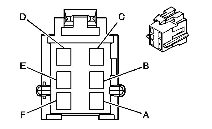
|
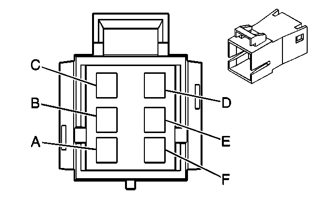
| ||||||||||||||
|---|---|---|---|---|---|---|---|---|---|---|---|---|---|---|---|
Connector Part Information |
| Connector Part Information |
| ||||||||||||
Pin | Wire Color | Circuit No. | Function | Pin | Wire Color | Circuit No. | Function | ||||||||
A | OG | 2740 | Battery Positive Voltage | A | OG | 2740 | Battery Positive Voltage | ||||||||
B | OG | 4440 | Battery Positive Voltage (CD6) | B | OG | 4440 | Battery Positive Voltage (CD6) | ||||||||
C | OG | 3640 | Battery Positive Voltage | C | OG | 3640 | Battery Positive Voltage | ||||||||
D | BK | 1550 | Ground | D | BK | 1550 | Ground | ||||||||
E | L-BU | 2288 | LGM Class 2 Serial Data | E | L-BU | 2288 | LGM Class 2 Serial Data | ||||||||
F | BN | 2509 | Left Rear Park Lamps Supply Voltage | F | BN | 2509 | Left Rear Park Lamps Supply Voltage | ||||||||
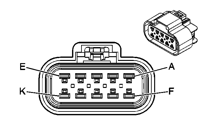
|
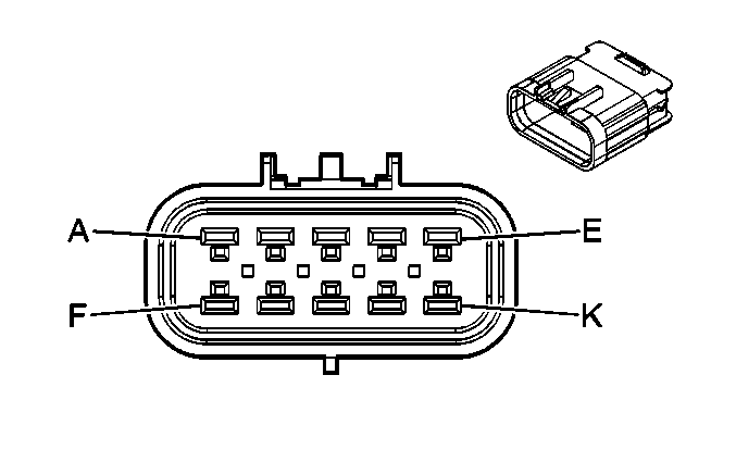
| ||||||||||||||
|---|---|---|---|---|---|---|---|---|---|---|---|---|---|---|---|
Connector Part Information |
| Connector Part Information |
| ||||||||||||
Pin | Wire Color | Circuit No. | Function | Pin | Wire Color | Circuit No. | Function | ||||||||
A | OG | 2540 | Battery Positive Voltage | A | OG | 2540 | Battery Positive Voltage | ||||||||
B | BK | 1650 | Ground | B | BK | 1650 | Ground | ||||||||
C | OG | 2740 | Battery Positive Voltage | C | OG | 2740 | Battery Positive Voltage | ||||||||
D | OG | 3640 | Battery Positive Voltage | D | OG | 3640 | Battery Positive Voltage | ||||||||
E | YE | 820 | CHMSL Supply Voltage | E | YE | 820 | CHMSL Supply Voltage | ||||||||
F | BN | 2509 | Left Rear Park Lamps Supply Voltage | F | BN | 2509 | Left Rear Park Lamps Supply Voltage | ||||||||
G | L-BU | 2288 | EGM Class 2 Serial Data | G | L-BU | 2288 | EGM Class 2 Serial Data | ||||||||
H | OG | 3940 | Battery Positive Voltage | H | OG | 3940 | Battery Positive Voltage | ||||||||
J-K | -- | -- | Not Used | J-K | -- | -- | Not Used | ||||||||
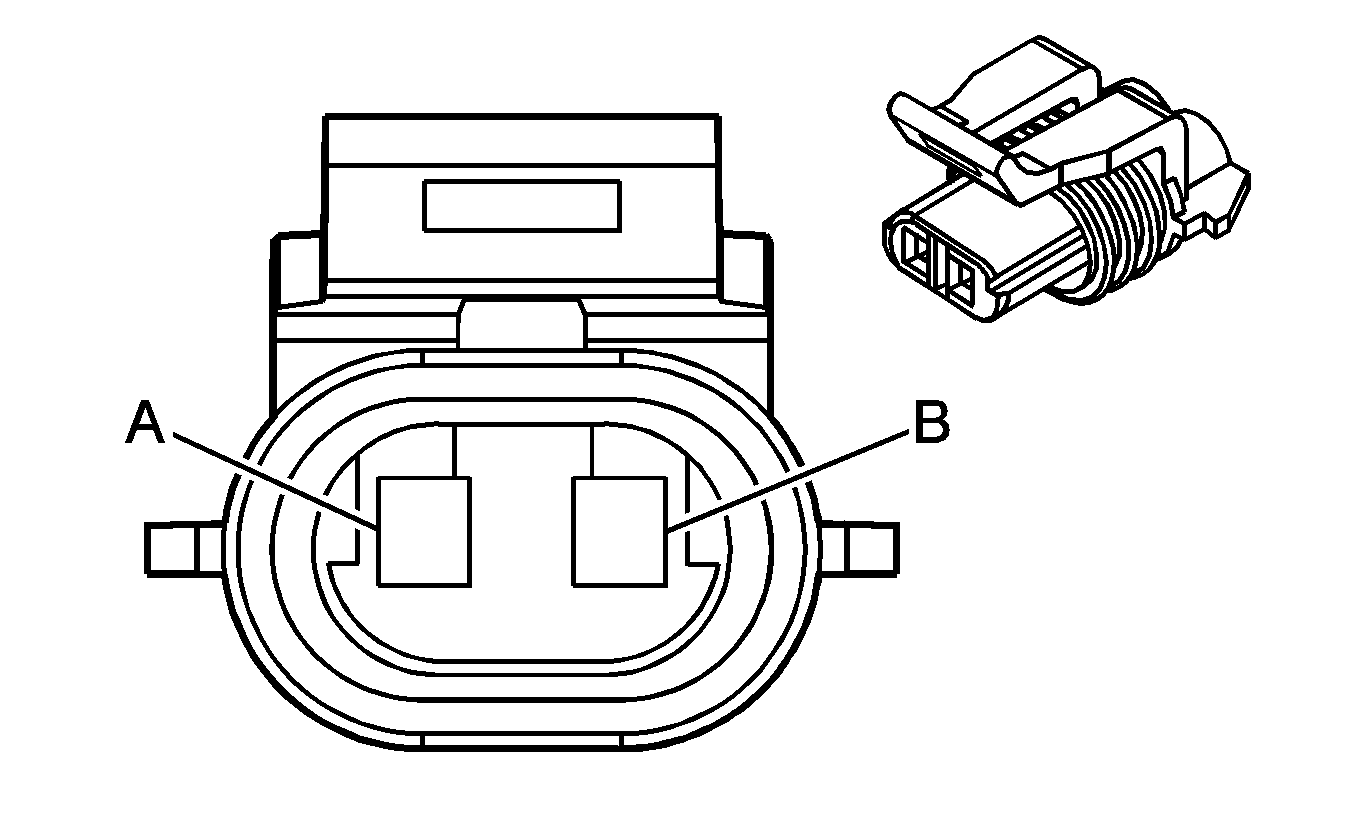
|
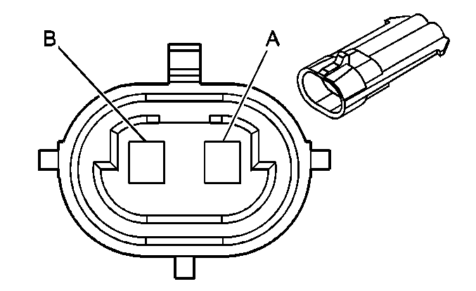
| ||||||||||||||
|---|---|---|---|---|---|---|---|---|---|---|---|---|---|---|---|
Connector Part Information |
| Connector Part Information |
| ||||||||||||
Pin | Wire Color | Circuit No. | Function | Pin | Wire Color | Circuit No. | Function | ||||||||
A | BN | 2509 | Left Rear Park Lamps Supply Voltage | A | BN | 2509 | Left Rear Park Lamps Supply Voltage | ||||||||
B | BK | 1550 | Ground | B | BK | 1550 | Ground | ||||||||

|

| ||||||||||||||
|---|---|---|---|---|---|---|---|---|---|---|---|---|---|---|---|
Connector Part Information |
| Connector Part Information |
| ||||||||||||
Pin | Wire Color | Circuit No. | Function | Pin | Wire Color | Circuit No. | Function | ||||||||
A | BN | 2509 | Left Rear Park Lamps Supply Voltage | A | BN | 2509 | Left Rear Park Lamps Supply Voltage | ||||||||
B | BK | 1650 | Ground | B | BK | 1650 | Ground | ||||||||
C | D-BU | 2201 | Endgate Ajar Switch Low Reference | C | D-BU | 2201 | Endgate Ajar Switch Low Reference | ||||||||
D | -- | -- | Not Used | D | -- | -- | Not Used | ||||||||
E | D-GN/WH | 5454 | Endgate Swing Latch Switch Signal | E | D-GN/WH | 5454 | Endgate Swing Latch Switch Signal | ||||||||
F | D-BU/WH | 5455 | Endgate Drop Latch Switch Signal | F | D-BU/WH | 5455 | Endgate Drop Latch Switch Signal | ||||||||
G | L-BU/BK | 5453 | Endgate Key Cylinder Up Signal | G | L-BU/BK | 5453 | Endgate Key Cylinder Up Signal | ||||||||
H | L-GN/BK | 5452 | Endgate Key Cylinder Down Signal | H | L-GN/BK | 5452 | Endgate Key Cylinder Down Signal | ||||||||
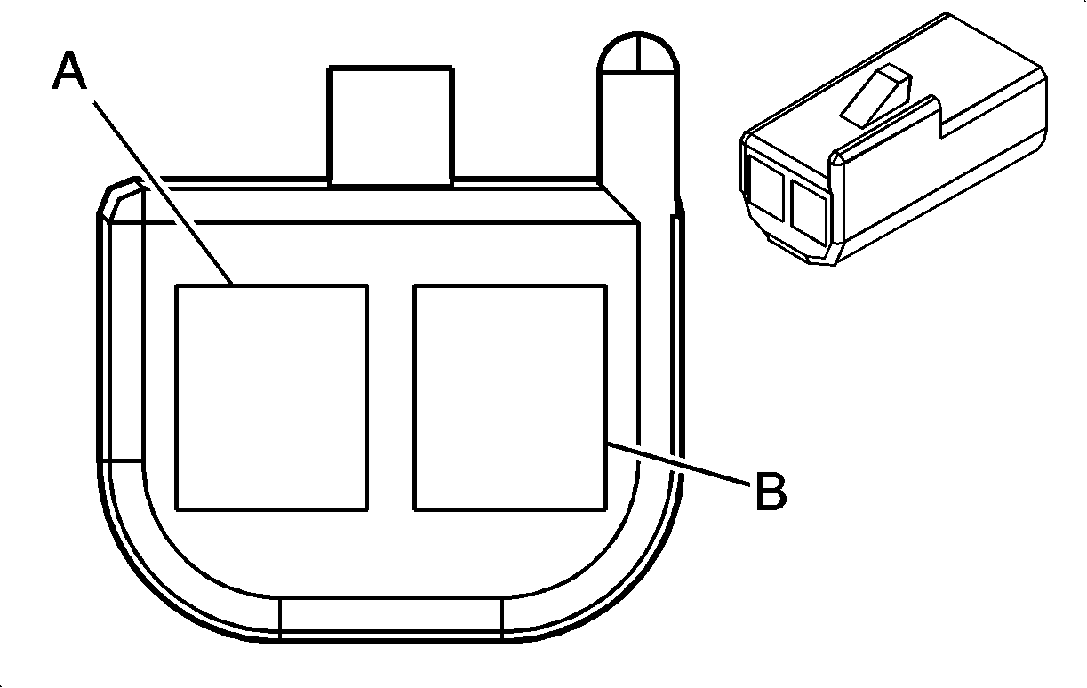
|
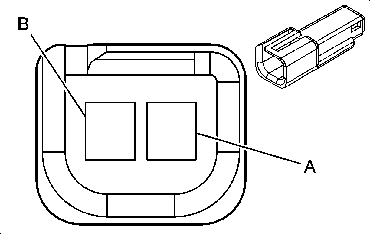
| ||||||||||||||
|---|---|---|---|---|---|---|---|---|---|---|---|---|---|---|---|
Connector Part Information |
| Connector Part Information |
| ||||||||||||
Pin | Wire Color | Circuit No. | Function | Pin | Wire Color | Circuit No. | Function | ||||||||
A | GY/BK | 690 | Courtesy Lamp Supply Voltage | A | GY/BK | 690 | Courtesy Lamp Supply Voltage | ||||||||
B | OG | 1732 | Courtesy Lamp Supply Voltage | B | OG | 1732 | Courtesy Lamp Supply Voltage | ||||||||
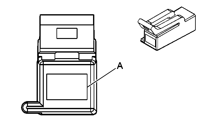
|
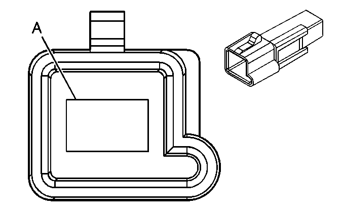
| ||||||||||||||
|---|---|---|---|---|---|---|---|---|---|---|---|---|---|---|---|
Connector Part Information |
| Connector Part Information |
| ||||||||||||
Pin | Wire Color | Circuit No. | Function | Pin | Wire Color | Circuit No. | Function | ||||||||
A | BK | 293 | Rear Defog Element Supply Voltage | A | PU | 293 | Rear Defog Element Supply Voltage | ||||||||

|

| ||||||||||||||
|---|---|---|---|---|---|---|---|---|---|---|---|---|---|---|---|
Connector Part Information |
| Connector Part Information |
| ||||||||||||
Pin | Wire Color | Circuit No. | Function | Pin | Wire Color | Circuit No. | Function | ||||||||
A | BK | 1550 | Ground | A | BK | 1550 | Ground | ||||||||
