For 1990-2009 cars only
Removal Procedure
Important: The intake manifold, throttle body, fuel rail, and injectors may be removed as an assembly. If not servicing the individual components, remove the manifold as a complete assembly.
- Remove the air cleaner outlet duct. Refer to Air Cleaner Resonator Outlet Duct Replacement in Engine Controls.
- Relieve the fuel system pressure. Refer to Fuel Pressure Relief in Engine Controls.
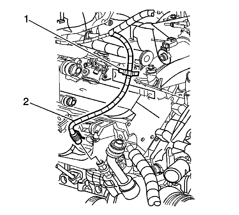
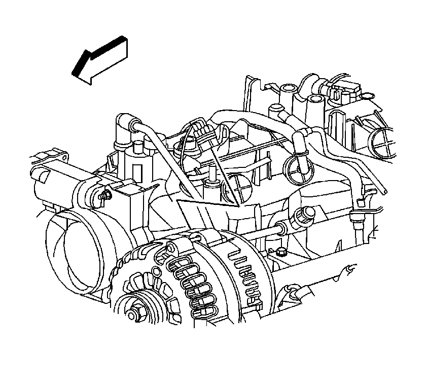
- Disconnect the air conditioning (A/C) compressor pressure switch electrical connector (2).
- Remove the harness clip from the cylinder head.
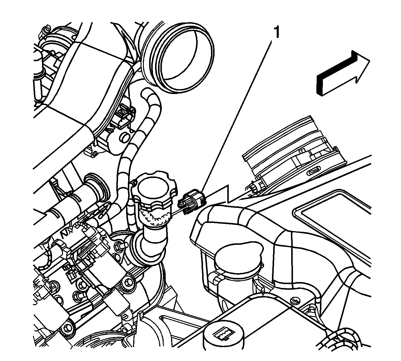
- Disconnect the mass air flow (MAF)/intake air temperature (IAT) sensor electrical connector (1).
- Remove the harness clips from the fuel rail.
- Disconnect the following electrical connectors:
- Perform the following steps in order to disconnect the fuel injector electrical connector.
- Disconnect the generator electrical connector.
- Disconnect the following electrical connectors:
- Remove the electrical harness clips from the fuel rail.
- Remove the knock sensor harness electrical connector from the intake manifold.
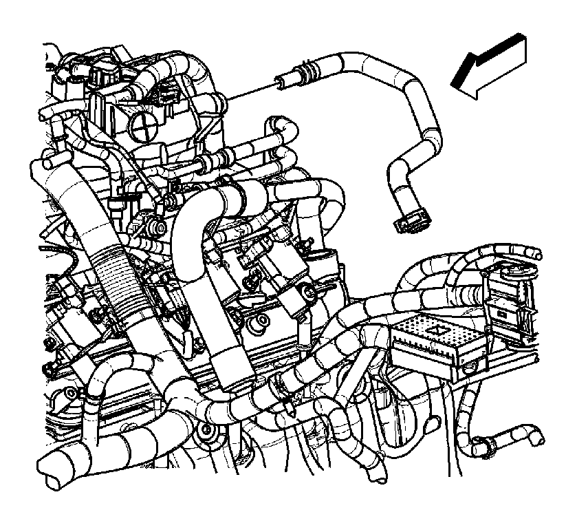
- Remove the positive crankcase ventilation (PCV) hose.
- Remove the heater water shutoff valve actuator inlet hose from the intake manifold.
- Remove the evaporative emission (EVAP) purge solenoid vent tube by performing the following:
- Remove the vacuum brake booster hose from the rear of the intake manifold.
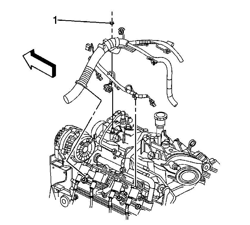
- Remove the upper engine wire harness retainer nut (1).
- Reposition the upper engine wire harness aside.
- Remove the intake manifold bolts.
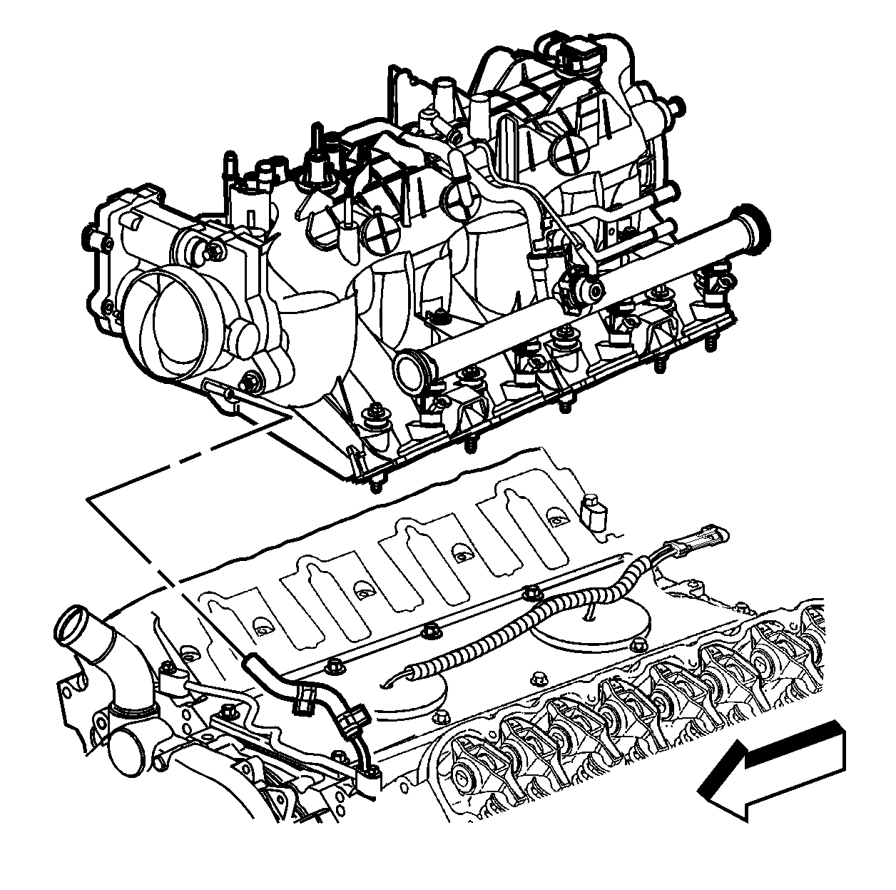
- Remove the intake manifold.
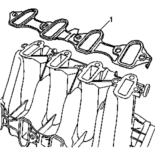
- Remove the intake manifold gaskets (1) from the intake manifold.
- Discard the old intake manifold gaskets.
- If necessary, clean and inspect the intake manifold. Refer to Intake Manifold Cleaning and Inspection .
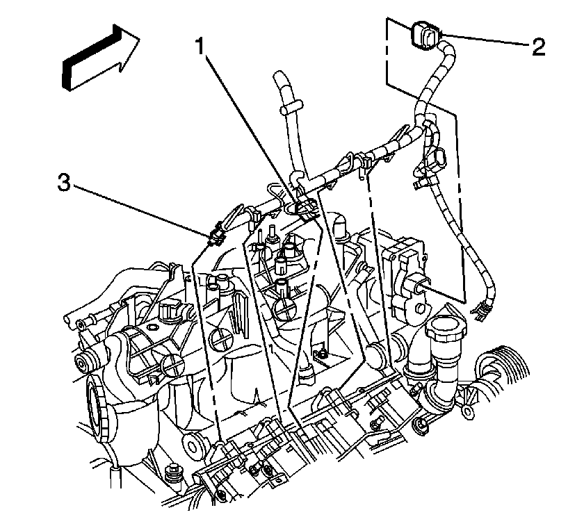
| • | Main coil (1) |
| • | Electronic throttle control (ETC) (2) |
| • | Fuel injectors (3) |
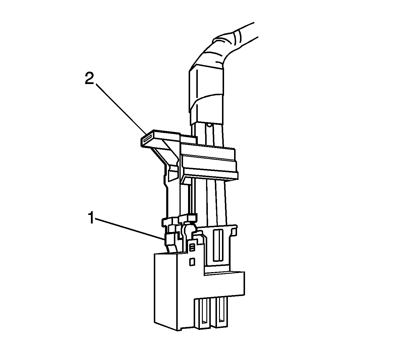
| 8.1. | Mark the connectors to their corresponding injectors to ensure correct reassembly. |
| 8.2. | Pull the connector position assurance (CPA) retainer (2) on the connector up 1 click. |
| 8.3. | Push the tab (1) on the connector in. |
| 8.4. | Disconnect the fuel injector electrical connector. |
| 8.5. | Repeat the steps for each injector electrical connector. |
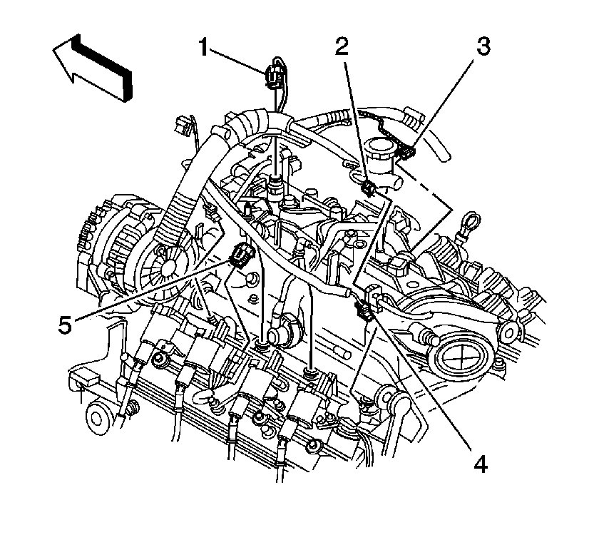
| • | Evaporative emission (EVAP) purge solenoid (1) |
| • | Knock sensor (2) |
| • | Manifold absolute pressure (MAP) sensor (3) |
| • | Main coil (5) |
| • | Fuel injectors (4) |
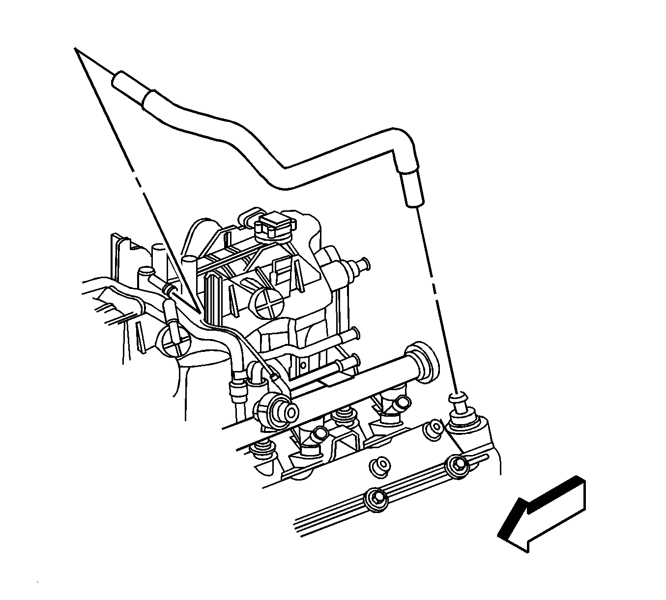
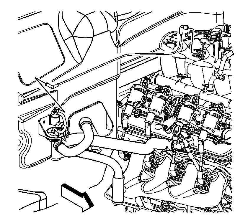
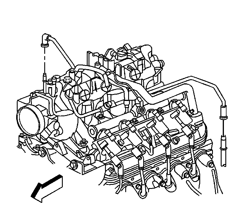
| 15.1. | Remove the EVAP tube end from the solenoid. |
| 15.2. | Squeeze the EVAP pipe quick connect fitting retainer together. |
| 15.3. | Remove the EVAP tube end from the vapor pipe. |
Installation Procedure
- Install NEW intake manifold gaskets (1) to the intake manifold.
- Install the intake manifold.
- Apply a 5 mm (0.20 in) bead of threadlock GM P/N 12345382, (Canadian P/N 10953489) or equivalent to the threads of the intake manifold bolts.
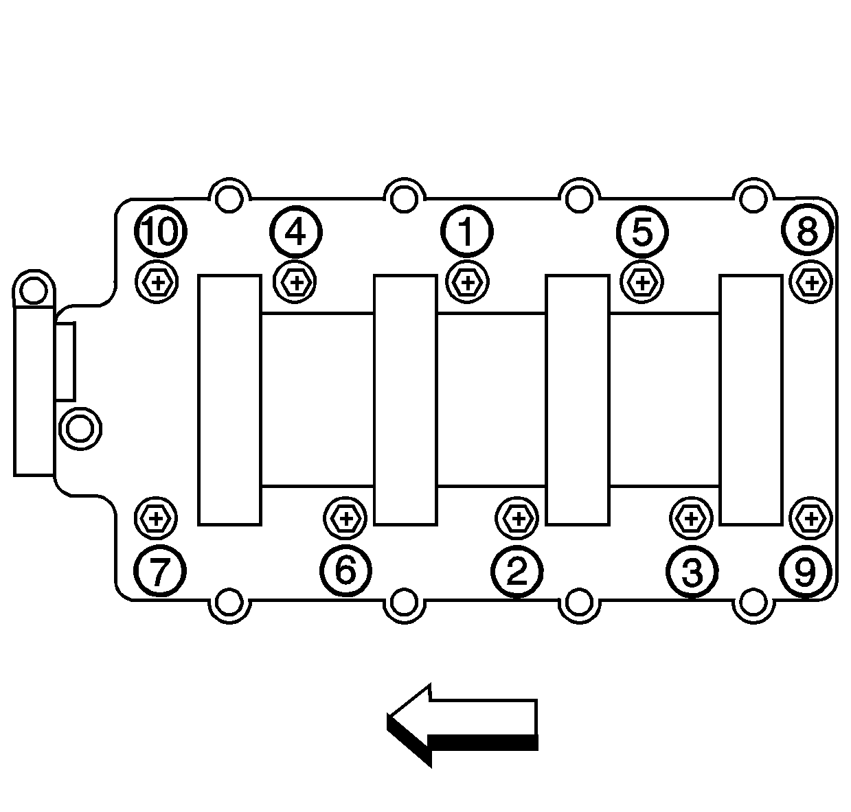
- Install the intake manifold bolts.
- Tighten the bolts a first pass in sequence to 5 N·m (44 lb in).
- Tighten the bolts a final pass in sequence to 10 N·m (89 lb in).
- Route the electrical harness into position over the engine.
- Install the engine harness bracket nut (1).
- Install the vacuum brake booster hose to the rear of the intake manifold.
- Install the EVAP purge solenoid vent tube.
- Install the heater water shutoff valve actuator inlet hose to the intake manifold.
- Install the PCV hose.
- Install the knock sensor harness electrical connector to the intake manifold.
- Connect the following electrical connectors:
- Perform the following steps in order to connect the fuel injector electrical connectors.
- Install the harness clips to the fuel rail.
- Connect the generator electrical connector.
- Connect the following electrical connectors:
- Install the electrical harness clips to the fuel rail.
- Connect the A/C compressor pressure switch electrical connector (2).
- Install the harness clip to the cylinder head.
- Connect the MAF/IAT sensor electrical connector (1).
- Install the air cleaner outlet duct. Refer to Air Cleaner Resonator Outlet Duct Replacement in Engine Controls.
- Install the fuel fill cap.
- Connect the negative battery cable. Refer to Battery Negative Cable Disconnection and Connection in Engine Electrical.
- Use the following procedure in order to inspect for leaks:


Notice: Refer to Fastener Notice in the Preface section.
Tighten

Tighten
Tighten the nut to 10 N·m (89 lb in).


| • | EVAP purge solenoid (1) |
| • | Knock sensor (2) |
| • | MAP sensor (3) |
| • | Main coil (5) |
| • | Fuel injectors (4) |

| 13.1. | Install the connectors to their corresponding injectors to ensure correct reassembly. |
| 13.2. | Connect the fuel injector electrical connector. |
| 13.3. | Push the CPA retainer (2) on the connector in one click. |
| 13.4. | Repeat the steps for each injector electrical connector. |


| • | Main coil (1) |
| • | ETC (2) |
| • | Fuel injectors (3) |


| 24.1. | Turn the ignition ON, with the engine OFF, for 2 seconds. |
| 24.2. | Turn the ignition OFF for 10 seconds. |
| 24.3. | Turn the ignition ON, with the engine OFF. |
| 24.4. | Inspect for fuel leaks. |
